Table of Contents
Advertisement
Quick Links
Advertisement
Table of Contents

Related Manuals for Advantech PCA-6654


Summary of Contents for Advantech PCA-6654
- Page 1 PCA-6654/6654L Video Display Card for Flat Panel and CRT...
- Page 2 Copyright Notice This document is copyrighted by Advantech Co., Ltd. All rights are reserved. Advantech Co., Ltd. reserves the right to make improvements to the products described in this manual at any time without notice. No part of this manual may be reproduced, copied, translated, or transmitted in any form or by any means without the prior written permission of Advantech Co., Ltd.
-
Page 3: Packing List
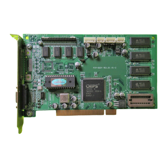
Packing List Before you set up the PCA-6654/6654L, make sure that the following materials have been included with the package, and that this manual is in good condition. If anything is missing or damaged, contact your dealer immediately: • PCA-6654/6654L card •... - Page 4 PCA-6654 Board Layout PCA-6654L Board Layout...
-
Page 5: Additional Information And Assistance
Additional Information and Assistance 1. Visit the Advantech web sites at www.advantech.com or www.advantech.com.tw where you can find the latest information about the product. 2. Contact your distributor, sales representative, or Advantech's customer service center for technical support if you need additional assistance. -
Page 6: Safety Instructions
The sound pressure level at the operator's position according to IEC 704-1:1982 is equal to or less than 70 dB(A). DISCLAIMER: This set of instructions is given according to IEC 704-1. Advantech disclaims all responsibility for the accuracy of any statements contained herein. - Page 7 - Wenn das Gerät deutliche Anzeichen eines Defektes aufweist. Der arbeitsplatzbezogene Schalldruckpegel nach DIN 45 635 Teil 1000 beträgt 70dB(A) oder weiger. DISCLAIMER: This set of instructions is given according to IEC704-1. Advantech disclaims all responsibility for the accuracy of any statements contained herein.
-
Page 8: Table Of Contents
Contents Chapter 1 Introduction ..........1 Description ................2 Specifications ..............3 Driver Support ..............4 Utility Support ..............5 Video BIOS .................5 Simultaneous Display Mode ..........6 Chapter 2 Hardware Setup ........... 7 Hardware Configuration ...........8 Jumpers and Connectors ...........9 Setting jumpers ..............9 Jumpers, Connectors and Switches ........10 Connectors for Adjuster ..........10 J4 ..................10 J5 ..................10... - Page 9 Installation for Windows 95 ..........27 Installation for Windows NT .......... 30 Installation for OS/2 ............32 Further Information ............35 Chapter 4 FPM Receiver Setup (PanelLink) (for PCA-6654 only) ........37 Introduction ..............38 Jumpers and Connectors ..........39 Setting jumpers ..............39 Connectors ................40 Connectors for Adjuster ..........40...
- Page 10 Appendix A Pin Assignments - PCA-6654/6654L ..63 A.1 CRT Display (CN1) ............64 A.2 Flat Panel Display (CN2) ..........65 A.3 Flat Panel Display Header (JP1) ........66 A.4 Keyboard Connector (J3) ..........67 A.5 Backlight Power Connector (J10) ........67 Appendix B Pin Assignments - FPM Receiver (PanelLink) ..........
-
Page 11: Chapter 1 Introduction
Introduction • Description • Specifications • Driver Support • Utility Support • Video BIOS • Simultaneous Display Mode... -
Page 12: Description
1.1 Description The PCA-6654/6654L is based on the CHIPS VGA flat panel/CRT controller and is fully IBM VGA compatible. This controller offers a large set of extended functions and higher resolutions, and it supports simultaneous functioning. Since the PCA-6654/6654L VGA card is fully compatible, you do not require any special drivers to operate in standard modes. -
Page 13: Specifications
1.2 Specifications Chipset: CHIPS 65550, integrated flat panel/CRT VGA controller Slot: High performance 32-bit PCI bus add-on card BIOS: 27C512, multiple panel support (8 panels built in) Memory: 2 MB EDO DRAM on board 256 K x 16 DRAM sockets for frame buffer (optional) Windows GUI (Graphic User Interface) accelerator: 64-bit Graphics Engine Simultaneous hardware cursor and pop-up window:... -
Page 14: Driver Support
Connectors: MDR-26 for flat panel display (PanelLink) DB-15 for CRT Built-in 44-pin header for Advantech standard flat panel pin assignment Built-in housing to connect VR for adjusting contrast/brightness Power: On-board DC-DC converter supplies LCD bias voltage LCD backlight power supplied... -
Page 15: Utility Support
1.4 Utility Support The utility provides: CT.COM Enable CRT display only FP.COM Enable panel display only SM.COM Enable both displays at the same time REVERSE.EXE Reverse the displays' colors READBIOS.EXE Read the VGA BIOS information TESTDDC.EXE Test if the VGA BIOS supports DDC These utilities are only supported in DOS mode, and can only be used for testing. -
Page 16: Simultaneous Display Mode
1.6 Simultaneous Display Mode The PCA-6654/6654L supports simultaneous display to a CRT monitor and a flat panel display. The flat panel may be TFT, DSTN or MONO. If you use a DSTN LCD in this mode, the display must be under 16/256 colors or the CRT and flat panel screens will tremble. -
Page 17: Chapter 2 Hardware Setup
Hardware Setup • Hardware Configuration • Jumpers and Connectors • Jumpers, Connectors and Switches • Connectors for Adjuster • Board Layout - Jumpers, Connectors and Switches • Jumper and Switch Settings • LCD Setup - Preliminary - TFT LCD Setup - DSTN LCD Setup - MONO LCD Setup... -
Page 18: Hardware Configuration
2.1 Hardware Configuration The PCA-6654/6654L is based on chipset 65550 and has high performance, a simple configuration, and fully supported LCD/CRT. B I O S Address Data R G B C R T H/V Sync Display DDC CLK/Data A d d r e s s... -
Page 19: Jumpers And Connectors
2.2 Jumpers and Connectors Setting jumpers You can configure your PCA-6654/6654L to match the needs of your application by setting jumpers. A jumper is the simplest kind of electrical switch. It consists of two metal pins and a small metal clip (often protected by a plastic cover) that slides over the pins to connect them. -
Page 20: Jumpers, Connectors And Switches
; voltage range +5 ~ +40 V or 0 ~ -40 V, depending on the jumper setting. This is a 3-pin housing. Connect a 500 Ω external VR to adjust V voltage range 0 ~ +4.3 V. PCA-6654/6654L User's Manual... - Page 21 2.5 Board Layout - Jumpers, Connectors and Switches J8: LCD bias voltage select J4: DSTN LCD contrast J7: LCD bias voltage adjustment select (MONO) SW2: LCD clock J5: MONO LCD configuration select contrast adjustment JP1: Flat panel display header SW1: LCD type select J9: LCD SW3: LCD control...
-
Page 22: Jumper And Switch Settings
2.6.1 LCD signal level select (J6) * 5 V 3.3 V * default setting 2.6.2 LCD bias voltage select (MONO) (J7) [+5 V ~ +40 V] * -V [0 V ~ -40 V] * default setting PCA-6654/6654L User's Manual... -
Page 23: Lcd Bias Voltage Select (J8)
2.6.3 LCD bias voltage select (J8) [+5 ~ +40 V or 0 ~ -40 V for MONO LCD] [0 ~ +2.8 V for DSTN LCD] * default setting 2.6.4 LCD type select (SW1) LCD type Pin 1 Pin 2 Pin 3 Pin 4 * 640 x 480 18-bit TFT 640 x 480 SHARP TFT... -
Page 24: Lcd Clock Configuration Select (For Panellink Only) (Sw2)
The LCD control signals are latched on rising edge of clock → OFF The SiI100 differential clock output is divided by two → ON * The SiI100 differential clock output is divided by one → OFF * default setting PCA-6654/6654L User's Manual... -
Page 25: Lcd Setup
2.7 LCD Setup 2.7.1 Preliminary Make sure that your LCD is ready to match your PCA-6654/6654L card prior to setting jumpers and switches. You will need to know your LCD specifications, which will be among the following: 1. LCD type: TFT, DSTN or MONO 2. -
Page 26: Tft Lcd Setup
6. Connect the LCD cable, inverter, inverter power wire, and VR assembly with wire to J9. (See Fig. 2-3.) 7. Plug the VGA card into the PCI slot. 8. Power on the system. 9. Adjust the screen brightness using the VR control. PCA-6654/6654L User's Manual... - Page 27 Inverter Figure 2-3: TFT LCD setup Chapter 2 Hardware Setup...
-
Page 28: Dstn Lcd Setup
All DSTN types 3. You do not need to set SW3. 4. Set J6 according to your LCD input power specifications: * 5 V 3.3 V * default setting 5. You do not need to set J7. PCA-6654/6654L User's Manual... - Page 29 6. Set J8 as follows: 7. Connect the LCD cable, inverter, inverter power wire, and VR assembly. The VR assembly with wire for brightness control should be connected to J9, and the wire for contrast control should be connected to J4. (See Fig. 2-4.) 8.
- Page 30 Inverter Figure 2-4: DSTN LCD setup PCA-6654/6654L User's Manual...
-
Page 31: Mono Lcd Setup
2.7.4 MONO LCD Setup Follow these steps: 1. Set SW1 as follows: LCD type Pin 1 Pin 2 Pin 3 Pin 4 640 x 480 MONO 2. Set SW2 as follows: LCD type Pin 1 Pin 2 Pin 3 Pin 4 640 x 480 MONO 3. - Page 32 The VR assembly with wire for brightness control should be connected to J9, and the wire for contrast control should be connected to J5. (See Fig. 2-5.) 14. Power on the system. 15. Adjust the screen brightness and contrast using the VR controls. PCA-6654/6654L User's Manual...
- Page 33 Inverter Figure 2-5: MONO LCD setup Chapter 2 Hardware Setup...
- Page 34 PCA-6654/6654L User's Manual...
-
Page 35: Chapter 3 Software Installation
Software Installation This chapter describes the installation and operation of the software drivers on the display driver diskettes included in your PCA-6654/6654L package. Sections in this chapter include: • Simultaneous Display Mode • Installation for Windows 95 • Installation for Windows NT •... -
Page 36: Simultaneous Display Mode
Both CRT and panel displays can be used simultaneously. The PCA-6654/6654L can be set in one of three configurations: on a CRT, on a flat panel display, or on both simultaneously. The system is initially set to simultaneous display mode. In the utility diskettes, there are three .COM files which can be used to select the display. -
Page 37: Installation For Windows 95
3.2 Installation for Windows 95 a. Select "Start" , "Settings" , "Control Panel". b. Double click the "display" icon. c. Choose the "Settings " label. d. Press the "Advanced Properties" button. a. Choose the "Adapter" label. b. Press the "Change..." button. - Page 38 Press the "Close" button. a. Press the "Yes" button b. Close all windows to reboot a. Repeat Step 1 on the previous page of this manual. b. The "Chips" label appears in "Display Properties". c. Adjust the resolution and color. PCA-6654/6654L User's Manual...
- Page 39 a. Choose the "Chips" label. b. Adjust the refresh rate and display device. c. Press the "OK" button a. Press the "OK" button to change the display setting. a. Press the "OK" button to confirm the setting. E N D Chapter 3 Software Drivers and Utilities...
-
Page 40: Installation For Windows Nt
Press the "Display Type" button. a. Press the "Change..." button. a. Press the "Have Disk..." button. a. Insert the "VGA Driver Windows 95&NT 4.0" disk into the floppy driver. b. Type "A:\WINNT4.115". c. Press the "OK" button. PCA-6654/6654L User's Manual... - Page 41 a. Press the "OK" button. a. Press the "Yes" button a. Press the "OK" button b. Close all windows to reboot a. Repeat Step 1 on the previous page of this manual. b. The "Chips" label appears in "Display Properties". c.
-
Page 42: Installation For Os/2
Press the "OK" button to shut down. b. Reboot again. a. Select "OS/2 System", "System Setup", "Display Driver Install". b. Enable "Primary Display". c. Press the "OK" button. a. Select "Chips & Technologies 65550/554/555". b. Press the "OK" button. PCA-6654/6654L User's Manual... - Page 43 a. Select "Install Using Defaults for Monitor Type". b. Press the "OK" button. a. Type "A:\" . b. Press the "Install..." button. a. Insert the "VGA Driver OS/2" disk into the floppy driver. b. Press the "OK" button. a. Press the "OK" button to shut down and restart the system.
- Page 44 Select "OS/2 System", "System Setup", "System". a. Select the "Screen" tab. b. Adjust the resolution, color and refresh rate. E N D PCA-6654/6654L User's Manual...
-
Page 45: Further Information
3.5 Further Information For further information about installation of the PCI/SVGA in your PCA-6654/6654L, including driver updates, troubleshooting guides and FAQ lists, visit the following web resources: C&T web site: www.chips.com Advantech web sites: www.advantech.com www.advantech.com.tw Chapter 3 Software Drivers and Utilities... - Page 46 PCA-6654/6654L User's Manual...
-
Page 47: Chapter 4 Fpm Receiver Setup (Panellink) (For Pca-6654 Only)
FPM Receiver Setup (PanelLink) (for PCA-6654 only) • Introduction • Jumpers and Connectors • Connectors • Connectors for Adjuster • Board Layout - Connectors • Jumpers and Switches • Board Layout - Jumpers and Switches • Jumper and Switch Settings •... -
Page 48: Introduction
4.1 Introduction The SiI100/140 (added into the PCA-6654) and SiI101/141 (added into the FPM-40 receiver) are high-speed digital video/graphics interconnection devices capable of supporting VGA to XVGA resolutions for TFT panels and VGA to XGA resolutions for DSTN LCD panels. These devices are based on Silicon Image's PanelLink... -
Page 49: Jumpers And Connectors
A pair of needle-nose pliers may be helpful when working with jumpers. If you have any doubts about the best hardware configuration for your application, contact your local distributor or sales representative before you make any changes. Chapter 4 FPM Receiver Setup (PanelLink) (for PCA-6654 only) -
Page 50: Connectors
This is a 3-pin housing. Connect a 500 Ω external VR to adjust V voltage range 0 ~ +4.3 V. This is a 3-pin housing. Connect a 500 Ω external VR to adjust V SAFE; voltage range 0 ~ +2.8 V. PCA-6654/6654L User's Manual... -
Page 51: Board Layout - Connectors
J11: FCC connector connector (A) for flat panel display JP4: Flat cable panel display extension J7: DSTN LCD J6: Extension contrast power adjustment Figure 4-1: Board layout - connectors Chapter 4 FPM Receiver Setup (PanelLink) (for PCA-6654 only) -
Page 52: Jumpers And Switches
4.6 Jumpers and Switches Label Function LCD bias voltage select LCD signal level select LCD bias voltage select (MONO) LCD input clock select Backlight level select Power down select LCD type select LCD clock configuration select PCA-6654/6654L User's Manual... -
Page 53: Board Layout - Jumpers And Switches
(MONO) S2: LCD clock configuration select J14: LCD input J8: LCD signal clock select level select J16: Power down select Figure 4-3: Board layout - jumpers and switches Chapter 4 FPM Receiver Setup (PanelLink) (for PCA-6654 only) -
Page 54: Jumper And Switch Settings
4.8.1 LCD bias voltage select (J5) [+5 ~ +40 V or 0 ~ -40 V for MONO LCD] [0 ~ +2.8 V for DSTN LCD] * default setting 4.8.2 LCD signal level select (J8) * 5 V 3.3 V * default setting PCA-6654/6654L User's Manual... -
Page 55: Lcd Bias Voltage Select (Mono) (J13)
4.8.4 LCD input clock select (J14) * Divided by one Divided by two * default setting 4.8.5 Backlight level select (J15) * ENAV [high level] /ENAV [low level] * default setting Chapter 4 FPM Receiver Setup (PanelLink) (for PCA-6654 only) -
Page 56: Power Down Select (J16)
Power down * Normal * default setting 4.8.7 LCD type select (S1) LCD type Pin 1 Pin 2 Pin 3 Pin 4 * 640 x 480 DSTN 800 x 600 DSTN 1024 x 768 DSTN * default setting PCA-6654/6654L User's Manual... -
Page 57: Lcd Clock Configuration Select (S2)
ON OFF 24-bit DSTN divided by 4/negative/blanked low OFF X OFF OFF * default setting # Termination resistor range selection: ON: 55 ~ 70 Ω OFF: 40 ~ 57 Ω (default) Chapter 4 FPM Receiver Setup (PanelLink) (for PCA-6654 only) -
Page 58: Lcd Setup
Vmax. 7. Backlight brightness voltage range in inverter. You should also have: 1. PanelLink cable (refer to J10 and PCA-6654 CN2) 2. LCD cable (refer to LCD, JP3/JP4 or J11/J12 pin assignments) 3. Inverter (refer to LCD specifications) 4. Inverter power wire (refer to inverter and J3) 5. -
Page 59: Tft Lcd Setup
4. You do not need to set J6, J7 and J8. FPM Receiver 5. Set S1 as follows, for all TFT LCDs: LCD type Pin 1 Pin 2 Pin 3 Pin 4 All TFT types Chapter 4 FPM Receiver Setup (PanelLink) (for PCA-6654 only) - Page 60 7. You do not need to set J5. 8. Set J8 as follows: * 5 V 3.3 V * default setting 9. You do not need to set J13. 10. Set J14 as follows: * Divided by one Divided by two * default setting PCA-6654/6654L User's Manual...
- Page 61 VR assembly with wire to J2. (See Fig. 4-4.) 14. Plug the VGA card into the PCI slot. 15. Power on the system. 16. Adjust the screen brightness using the VR control. Chapter 4 FPM Receiver Setup (PanelLink) (for PCA-6654 only)
- Page 62 Inverter PanelLink cable Figure 4-4: TFT LCD setup PCA-6654/6654L User's Manual...
-
Page 63: Dstn Lcd Setup
DATA EDGE Falling edge Rising edge CLOCK EDGE Falling edge Rising edge HALF CLOCK Divided by two Divided by one 4. You do not need to set J6, J7 or J8. Chapter 4 FPM Receiver Setup (PanelLink) (for PCA-6654 only) - Page 64 2/negative/blanked low OFF X ON OFF 24-bit DSTN divided by 4/negative/blanked low OFF X OFF OFF # Termination resistor range selection: ON: 55 ~ 70 Ω OFF: 40 ~ 57 Ω 7. Set J5 as follows: PCA-6654/6654L User's Manual...
- Page 65 * Divided by one Divided by two * default setting 11. Set J15 as follows: * ENAV [high level] /ENAV [low level] * default setting 12. Set J16 as follows: Normal Chapter 4 FPM Receiver Setup (PanelLink) (for PCA-6654 only)
- Page 66 VR assembly with wire for brightness to J2 and for contrast to J7. (See Fig. 4-5.) 14. Plug the VGA card into the PCI slot. 15. Power on the system. 16. Adjust the screen brightness and contrast using the VR controls. PCA-6654/6654L User's Manual...
- Page 67 Inverter PanelLink cable Figure 4-5: DSTN LCD setup Chapter 4 FPM Receiver Setup (PanelLink) (for PCA-6654 only)
-
Page 68: Mono Lcd Setup
HALF CLOCK Divided by two Divided by one 4. You do not need to set J6, J7 or J8. FPM Receiver 5. Set S1 as follows: LCD type Pin 1 Pin 2 Pin 3 Pin 4 MONO PCA-6654/6654L User's Manual... - Page 69 OFF: 40 ~ 57 Ω 7. Set J5 as follows: 8. Set J8 as follows: * 5 V 3.3 V * default setting 9. Set J13 as follows: * -V * default setting Chapter 4 FPM Receiver Setup (PanelLink) (for PCA-6654 only)
- Page 70 (See Fig. 4-6.) 14. Plug the VGA card into the PCI slot. 15. Short J1. 16. Power on the system. 17. Adjust VR1 to be V max. 18. Power off the system. 19. Remove the jumper on J1. PCA-6654/6654L User's Manual...
- Page 71 J2 and for contrast to J1. (See Fig. 4-6.) 21. Power on the system. 22. Adjust the screen brightness and contrast using the VR controls. Chapter 4 FPM Receiver Setup (PanelLink) (for PCA-6654 only)
- Page 72 Inverter PanelLink cable Figure 4-6: MONO LCD setup PCA-6654/6654L User's Manual...
-
Page 73: Appendix A Pin Assignments - Pca-6654/6654L
Pin Assignments - PCA-6654/6654L • CRT Display (CN1) • Flat Panel Display (CN2) • Flat Panel Display Header (JP1) • Keyboard Connector (J3) • Backlight Power Connector (J10) -
Page 74: Crt Display (Cn1)
A.1 CRT Display (CN1) Table A-1: CRT display (CN1): Signal Signal +5 V DDC Data Horizontal sync Vertical sync DDC clock PCA-6654/6654L User’s Manual... -
Page 75: Flat Panel Display (Cn2)
Table A-2: Flat panel display (CN2) Signal Signal +12 V TX1+ +3.3 V +12 V TX2- TXC- TX2+ TXC+ KB_Data +3.3 V KB_Clock Power Down TX0- TX0+ +5 V +3.3 V +5 V TX1- Appendix A Pin Assignments - PCA-6654/6654L... -
Page 76: Flat Panel Display Header (Jp1)
A.3 Flat Panel Display Header (JP1) Table A-3: Flat panel display header (JP1) Signal Signal +12 V +12 V SAFE SAFE SAFE SFHCLK M/DE ENABKL PCA-6654/6654L User’s Manual... -
Page 77: Keyboard Connector (J3)
A.4 Keyboard Connector (J3) Table A-4: Keyboard connector (J3) Signal KB_Data KB_Clock A.5 Backlight Power Connector (J10) Table A-5: Backlight power connector (J10) Signal +12 V ENABKL +5 V Appendix A Pin Assignments - PCA-6654/6654L... - Page 78 PCA-6654/6654L User’s Manual...
-
Page 79: Appendix B Pin Assignments - Fpm Receiver (Panellink)
Pin Assignments - FPM Receiver (PanelLink) • Flat Cable Panel Display Header (JP3) • Flat Cable Panel Display Extension Header (JP4) • Backlight Power (J3) • Extension Power (J6) • Flat Panel Display (J10) • FFC Connector (A) For Flat Panel Display (J11) •... -
Page 80: Flat Cable Panel Display Header (Jp3)
B.1 Flat Cable Panel Display Header (JP3) Table B-1: Flat cable panel display header (JP3) Signal Signal +12 V +12 V SAFE SAFE SAFE SHFCLK M/DE ENABKL PCA-6654/6654L User’s Manual... -
Page 81: Flat Cable Panel Display Extension Header (Jp4)
B.2 Flat Cable Panel Display Extension Header (JP4) Table B-2: Flat cable panel display extension header (JP4) Signal Signal SAFE +5 V B.3 Backlight Power (J3) Table B-3: Backlight power (J3) Signal Signal +12 V ENABKL +5 V Appendix B Pin Assignments - FPM Receiver (PanelLink) -
Page 82: Flat Panel Display (J10)
B.5 Flat Panel Display (J10) Table B-5: Flat panel display (J10) Signal Signal +12 V +12 V TXC- TXC+ +3.3 V TX0- TX0+ +3.3 V TX1- TX1+ +3.3 V TX2- TX2+ KB_Data KB_Clock Power Down +5 V +5 V PCA-6654/6654L User’s Manual... -
Page 83: Ffc Connector (A) For Flat Panel Display (J11)
B.6 FFC Connector (A) For Flat Panel Display (J11) Table B-6: FFC connector (A) for flat panel display (J11) Signal Signal Appendix B Pin Assignments - FPM Receiver (PanelLink) -
Page 84: Ffc Connector (B) For Flat Panel Display (J12)
B.7 FFC Connector (B) For Flat Panel Display (J12) Table B-7: FFC connector (B) for flat panel display (J12) Signal Signal SHFCLK M/DE SAFE SAFE SAFE SAFE SAFE B.8 Keyboard Connector (J17) Table B-8: Keyboard connector (J17) Signal Signal KB_Clock KB_Data +5 V PCA-6654/6654L User’s Manual...
Need help?
Do you have a question about the PCA-6654 and is the answer not in the manual?
Questions and answers