Table of Contents
Advertisement
Quick Links
Advertisement
Table of Contents

Related Manuals for Advantech SOM-2533


Summary of Contents for Advantech SOM-2533
- Page 1 User Manual SOM-2533 CPU Computer on Module...
- Page 2 No part of this manual may be reproduced, copied, translated, or transmitted in any form or by any means without the prior written permission of Advantech Co., Ltd. The information provided in this manual is intended to be accurate and reliable.
- Page 3 This product has passed the CE test for environmental specifications when shielded cables are used for external wiring. We recommend the use of shielded cables. This type of cable is available from Advantech. Please contact your local supplier for ordering information.
- Page 4 Document Feedback To assist us with improving this manual, we welcome all comments and constructive criticism. Please send all feedback in writing to support@advantech.com. Safety Precautions - Static Electricity Follow these simple precautions to protect yourself from harm and the products from damage.
- Page 5 In accordance with IEC 704-1:1982 specifications, the sound pressure level at the operator’s position shall not exceed 70 dB (A). DISCLAIMER: This set of instructions is given according to IEC 704-1. Advantech disclaims all responsibility for the accuracy of any statements contained herein.
- Page 6 SOM-2533 User Manual...
-
Page 7: Table Of Contents
Power Management..............9 1.3.10 Environment................10 1.3.11 MTBF ..................10 1.3.12 OS Support ................. 10 1.3.13 Advantech iManager ..............10 1.3.14 Power Consumption..............10 Table 1.9: Power Consumption Table (Watts)......10 1.3.15 Selection Guide w/ P/N ............... 11 Table 1.10:Selection Guide w/ P/N..........11 1.3.16 Packing List................. - Page 8 Figure 3.35Serial IO I2C2 Settings..........54 Figure 3.36Serial IO I2C4 Settings..........54 Figure 3.37Serial IO UART0 Settings......... 55 Figure 3.38SCS Configuration............ 56 Security Chipset..................57 Figure 3.39Security Chipset ............57 3.6.1 Secure Boot ................58 Figure 3.40Secure Boot.............. 58 SOM-2533 User Manual viii...
- Page 9 Other OS..................62 Advantech iManager ................63 Appendix A Pin Assignments .......65 SOM-2533 Pin Assignments ..............66 Table A.1: SOM-2533 Pin Assignments ........66 Appendix B Watchdog Timer ........75 Programming the Watchdog Timer ............76 Table B.1: Programming the Watchdog Timer......76...
- Page 10 SOM-2533 User Manual...
-
Page 11: Chapter 1 General Information
Chapter General Information This chapter gives background information on the SOM-2533 CPU Computer on Module. Sections include: Introduction Functional Block Diagram Product Specifications... -
Page 12: Introduction
SOM-2533 series modules feature SMARC 2.1.1 specifications and are equipped with the latest 12th Gen Intel® processors, including i3, N-Series, and Atom® x7000E Series. SOM-2533 supports up to 8 cores and yields 60% better CPU perfor- mance and improved graphics processing when compared with previous models. - Page 13 Serial Presence Detect – refers to serial EEPROM on DRAM that has DRAM Module configuration information Trusted Platform Module – chip to enhance the security features of a com- puter system UEFI Unified Extensible Firmware Interface Watchdog Timer SOM-2533 User Manual...
-
Page 14: Functional Block Diagram
Functional Block Diagram SOM-2533 User Manual... -
Page 15: Product Specifications
1/1/1 1/1/0 HDMI/DP++ DP++ MIPI-CSI SDIO Audio HDA/I2S2 SMBus Serial Port CANBus USB 2.0 USB 3.2 USB (OTG) PCIe (Gen3) SATA Watchdog GPIO 14/14 Management Boot Select JTAG (on board) Wi-Fi Module 0/(N/A) 0 (fTPM) Force Recov SOM-2533 User Manual... -
Page 16: Processor System
PCI Express x1: Supports 3 x PCIe x1 ports by default and 1 x optional PCle x1 port compliant with the PCIe Gen3 (8.0 GT/s) specification, configurable to PCIe x4 upon request. Several configurable combinations may need BIOS modifications. Please contact Advantech sales or FAE for more details. Table 1.5: PCIe x1 SMARC PCIe Lane... -
Page 17: Serial Bus
OC_1 OC_2 1.3.8.6 Supports HD-Audio and LPE Audio for DDI[1:0] (DisplayPort and HDMI), 1.8V signal level, up to 24 MHz serial data clock. 1.3.8.7 Audio I2S From ADL-N SOC I2S port 2 (following CRB, supports Linux only). SOM-2533 User Manual... - Page 18 BIOS_DIS#[1:0]. Table 1.8: BIOS BIOS_DIS#0 BIOS_DIS#1 Bootup Destination/Function Open Open Boot from Module SPI BIOS Open SPI_CS0# to Carrier Board, SPI_CS1# to Module SPI_CS0# to Module, SPI_CS1# to Carrier Board SOM-2533 User Manual...
-
Page 19: Power Management
There is support for various wake-up events to apply to different scenarios. Wake-on-LAN (WOL): Wake to S0 from S3/S4 USB Wake: Wake to S0 from S3/S4 PCIe Device Wake: depends on user inquiry and may need customized BIOS SOM-2533 User Manual... -
Page 20: Environment
1.3.9.5 Advantech S5 ECO Mode (Deep Sleep Mode) Advantech iManager provides additional features to allow the system to enter a very low suspend power mode – S5 ECO mode. In this mode, the module will cut all power including suspended and active power into the chipset and keep an on-module controller active. -
Page 21: Selection Guide W/ P/N
OS: Windows 10 Pro 1.3.14.1 Performance For reference performance or benchmark data to compare with other modules, please refer to the “Advantech COM Performance & Power Consumption Table”. 1.3.15 Selection Guide w/ P/N Table 1.10: Selection Guide w/ P/N LVDS/... -
Page 22: Development Board
1.3.19 Pin Description Advantech provides useful checklists for schematic design and layout routing. In the schematic checklist, it will specify details about each pin’s electrical properties and how to connect them for different user scenarios. In the layout checklist, it will specify the layout constraints and recommendations for trace length, impedance, and other necessary information during design. -
Page 23: Chapter 2 Mechanical Information
Chapter Mechanical Information This chapter gives mechanical information on the SOM-2533 CPU Computer on Module. Sections include: Board Information Mechanical Drawings Assembly Drawing... -
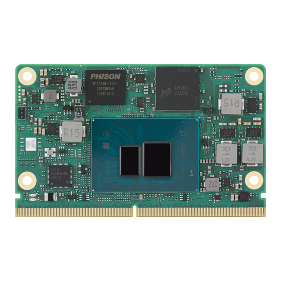
Page 24: Board Information
Board Information The figures below show the main chips on the SOM-2533 Computer-on-Module. Please be aware of these positions when designing a customer’s carrier board to avoid mechanical interference, and consider thermal solution contacts for best ther- mal dissipation performance. -
Page 25: Mechanical Diagrams
Mechanical Diagrams For more details on 2D/3D models, please look on the Advantech COM support ser- vice website: http://com.advantech.com Figure 2.3 Board Mechanical Diagram – Front Figure 2.4 Board Mechanical Diagram – Rear SOM-2533 User Manual... -
Page 26: Assembly Diagram
Figure 2.5 Board Mechanical Diagram – Side Assembly Diagram These figures demonstrate the assembly order of the thermal module and COM mod- ule to the carrier board. Figure 2.6 Assembly Drawing SOM-2533 User Manual... -
Page 27: Assembly Drawing
There are 4 reserved screw holes for SOM-2533 for pre-assembly of the heat spreader. Assembly Drawing There is a rubber solution implemented on the board to prevent the CPU from crack- ing. Please refer to the location of the rubber and consider the location when design- ing your carrier board. - Page 28 SOM-2533 User Manual...
-
Page 29: Chapter 3 Ami Bios
Chapter AMI BIOS This chapter gives BIOS setup information for the SOM-2533 CPU Computer on Module. Sections include: Introduction Entering Setup Hot/Operation Key Exiting the BIOS Setup Utility... -
Page 30: Introduction
This information is stored in flash ROM so it retains the setup information when the power is turned off. Entering Setup Turn on the computer and then press <DEL> or <ESC> to enter the Setup menu. SOM-2533 User Manual... -
Page 31: Main Setup
System Date using the <Arrow> keys. Enter new values through the keyboard. Press the <Tab> or the <Arrow> keys to move between fields. The date must be entered in MM/DD/YY format. The time must be entered in HH:MM:SS format. SOM-2533 User Manual... -
Page 32: Advanced Bios Features Setup
Embedded Controller Embedded Controller Parameters. Serial Port Console Redirection Console Redirection Settings USB Configuration USB Configuration Parameters Network Stack Configuration Network Stack Settings CSM Configuration CSM Configuration: Enable/Disable, Optional ROM execution settings, etc. SOM-2533 User Manual... -
Page 33: Cpu Configuration
Enable/Disable CPU Flex Ratio Programming. Active Efficient-cores Number of E-cores to enable in each processor package. Note: Number of Cores and E-cores are looked at together. When both are {0,0}, Pcode will enable all cores. SOM-2533 User Manual... -
Page 34: Power & Performance
3.4.2 Power & Performance Figure 3.5 Power & Performance CPU - Power Management Control CPU - Power Management Control Options. GT - Power Management Control GT - Power Management Control Options. SOM-2533 User Manual... - Page 35 Enable/Disable processor Turbo Mode (requires EMTTM enabled too). AUTO means enabled. Config TDP Configurations Configurable Processor Base Power (cTDP) Configurations. C states Enable/Disable CPU Power Management. Allows CPU to go to C states when it's not 100% utilized. SOM-2533 User Manual...
- Page 36 Power Limit2 in milliwatts. BIOS will round to the nearest 1/8W when program- ming. 0=no custom override. For 12.50W, enter 12500. The processor applies control policies such that the package power does not exceed this limit. SOM-2533 User Manual...
- Page 37 Custom value for Turbo Activation Ratio. Needs to be configured with valid val- ues from LFM to Max Turbo. 0 means it does not use a custom value. 3.4.2.2 GT - Power Management Control Figure 3.8 GT - Power Management Control SOM-2533 User Manual...
-
Page 38: Pch-Fw Configuration
When Disabled, ME will be put into ME Temporarily Disabled Mode. ME Unconfig on RTC Clear When Disabled, ME will not be unconfigured on RTC clear. Firmware Update Configuration Configure Management Engine Technology Parameters. SOM-2533 User Manual... - Page 39 3.4.3.1 Firmware Update Configuration Figure 3.10 Firmware Update Configuration Me FW Image Re-Flash Enable/Disable Me FW Image Re-Flash function. FW Update Enable/Disable ME FW Update function. SOM-2533 User Manual...
-
Page 40: Trusted Computing
TPM 1.2 will restrict support to TPM 1.2 devices; TPM 2.0 will restrict support to TPM 2.0 devices; Auto will support both with the default set to TPM 2.0 devices if not found; TPM 1.2 devices will be enumerated. SOM-2533 User Manual... -
Page 41: Acpi Settings
Enable/Disable System ability to Hibernate (OS/S4 Sleep State). This option may be not effective with some OS. ACPI Sleep State Select the highest ACPI sleep state the system will enter when the SUSPEND button is pressed. SOM-2533 User Manual... -
Page 42: Embedded Controller
Select Power Saving Mode. Serial Port 1 (SER1) Set Parameters of Serial Port 1 (SMARC SER1). Serial Port 2 (SER3) Set Parameters of Serial Port 2 (SMARC SER3). Hardware Monitor Monitor hardware status. SOM-2533 User Manual... - Page 43 3.4.6.1 Serial Port 1 Configuration Figure 3.14 Serial Port 1 Configuration Serial Port Enable/Disable Serial Port (COM). Change Settings Select optimal settings for a Super IO Device. Device Mode Change the Serial Port Mode. SOM-2533 User Manual...
- Page 44 3.4.6.2 Serial Port 2 Configuration Figure 3.15 Serial Port 2 Configuration Serial Port Enable/Disable Serial Port (COM). Change Settings Select optimal settings for a Super IO Device. Device Mode Change the Serial Port Mode. SOM-2533 User Manual...
- Page 45 3.4.6.3 Hardware Monitor Figure 3.16 Hardware Monitor SOM-2533 User Manual...
-
Page 46: Serial Port Console Redirection
3.4.7 Serial Port Console Redirection Figure 3.17 Serial Port Console Redirection Console Redirection Enable/Disable Console Redirection. Legacy Console Redirection Settings Legacy Console Redirection Settings. Console Redirection EMS Enable/Disable Console Redirection. SOM-2533 User Manual... -
Page 47: Usb Configuration
Maximum time the device will take before it properly reports itself to the Host Controller. 'Auto' uses the default value: for a Root port it is 100 ms, for a Hub port the delay is taken from the Hub descriptor. SOM-2533 User Manual... -
Page 48: Network Stack Configuration
3.4.9 Network Stack Configuration Figure 3.19 Network Stack Configuration Network Stack Enable/Disable the UEFI Network Stack. SOM-2533 User Manual... -
Page 49: Compatibility Support Module Configuration
3.4.10 Compatibility Support Module Configuration Figure 3.20 Compatibility Support Module Configuration CSM Support Enable/Disable CSM Support. SOM-2533 User Manual... -
Page 50: Smarc Gpio Configuration
3.4.11 SMARC GPIO Configuration Figure 3.21 SMARC GPIO Configuration GPIO0 SMARC GPIO0. GPIO1 SMARC GPIO1. GPIO2 SMARC GPIO2. GPIO3 SMARC GPIO3. GPIO4 SMARC GPIO4. GPIO5 SMARC GPIO5. GPIO6 SMARC GPIO6. SOM-2533 User Manual... -
Page 51: Chipset Setup
Chipset Setup Figure 3.22 Chipset Setup System Agent (SA) Configuration System Agent Parameters. PCH-I0 Configuration PCH parameters. SOM-2533 User Manual... -
Page 52: System Agent (Sa) Configuration
Memory Configuration Parameters. Graphic Configuration Graphics Configuration. VT-d VT-d capability. Above 4GB MMIO BIOS assignment Enable/Disable above 4GB memory mapped IO BIOS assignment. This is enabled automatically when the aperture size is set to 2048MB. SOM-2533 User Manual... - Page 53 3.5.1.1 Memory Configuration Figure 3.24 Memory Configuration 3.5.1.2 Graphics Configuration Figure 3.25 Graphics Configuration SOM-2533 User Manual...
- Page 54 Color depth and packing format. Dual LVDS mode – Dual LVDS Mode. – LCD Panel Type Select LCD panel used by Internal Graphics Device by selecting the appro- priate setup item. LVDS Clock Spreading – LVDS Clock Spreading. SOM-2533 User Manual...
-
Page 55: Pch-Io Configuration
SATA device option settings. USB Configuration USB Configuration settings. Security Configuration Security Configuration settings. HD Audio Configuration HD audio subsystem configuration settings. SerialIo Configuration SerialIo configuration settings. SCS Configuration Storage and Communication Subsystem (SCS) Configuration. SOM-2533 User Manual... - Page 56 0th is enabled, 0th will become visible. PCI Express Root Port 9 PCI Express Root Port Settings. PCI Express Root Port 10 PCI Express Root Port Settings. PCI Express Root Port 11 PCI Express Root Port Settings. SOM-2533 User Manual...
- Page 57 ASPM Set the ASPM Level: Force L0s – Force all links to L0s State AUTO – BIOS auto configure DISABLE – Disables ASPM. – Hot Plug PCI Express Hot Plug Enable/Disable. – PCIe Speed Configure PCIe Speed. SOM-2533 User Manual...
- Page 58 SATA Configuration Figure 3.30 SATA Configuration SATA Controller(s) Enable/Disable SATA Device. SATA Controller Speed Indicates the maximum speed the SATA controller can support. Port 0 Enable/Disable SATA Port. Port 1 Enable/Disable SATA Port. SOM-2533 User Manual...
- Page 59 3.5.2.3 USB Configuration Figure 3.31 USB Configuration xDCI Support Enable/Disable xDCI (USB OTG Device). USB Port Disable Override Selectively Enable/Disable the corresponding USB port from reporting a Device Connection to the controller. SOM-2533 User Manual...
- Page 60 Enable/Disable the PCH BIOS Lock Enable feature. It is required to be enabled to ensure SMM protection of flash. Force unlock on all GPIO pads If Enabled, BIOS will force all GPIO pads to be in the unlocked state. SOM-2533 User Manual...
- Page 61 3.5.2.5 HD Audio Subsystem Configuration Settings Figure 3.33 HD Audio Subsystem Configuration Settings HD Audio Control Detection of the HD-Audio device. Disabled=HDA will be unconditionally disabled. Enabled=HDA will be unconditionally enabled. SOM-2533 User Manual...
- Page 62 I2C0 and I2C1,2,3 UART0 and UART1,SPI0,1 UART2 and I2C4,5 UART 0 (00:30:00) cannot be disabled when: 1. Child device is enabled like CNVi Bluetooth (\_SB.PC00.UA00.BTH0) UART 0 (00:30:00) cannot be enabled when: 1. I2S Audio codec is enabled (\_SB.PC00.I2C0.HDAC) SOM-2533 User Manual...
- Page 63 Configure SerialIo Controller. Serial IO UART2 Settings Configure SerialIo Controller. SerialIO timing parameters Enables additional timing parameters for all SerialIo controllers. Defaults can be changed in each controller setting. A platform restart is required to apply changes. SOM-2533 User Manual...
- Page 64 Serial IO I2C2 Settings Figure 3.35 Serial IO I2C2 Settings Serial IO I2C4 Settings Figure 3.36 Serial IO I2C4 Settings SOM-2533 User Manual...
- Page 65 Disabled: No _PS0 _PS3 support, the device is left in D0, after initialization Enabled: _PS0 _PS3 that supports moving the device out of reset; Auto: _PS0 and _PS3 detection through ACPI if the device was initialized prior to first PG. If it was used, (DBG2) PG is disabled. SOM-2533 User Manual...
- Page 66 Enable/Disable SCS eMMC 5.1 HS400 Mode. Enable HS400 software tuning Software tuning should improve eMMC HS400 stability at the expense of boot time. Driver Strength Sets I/O driver strength. UFS 2.0 Controller 1 Enable/Disable the UFS 2.0 Controller. SOM-2533 User Manual...
-
Page 67: Security Chipset
Security Chipset Figure 3.39 Security Chipset Administrator Password Set the Setup Administrator Password. User Password Set the User Password. Secure Boot Secure Boot Configuration. SOM-2533 User Manual... -
Page 68: Secure Boot
System is in User mode. The mode change requires a plat- form reset. Secure Boot Mode Secure Boot mode options: Standard or Custom. In Custom mode, Secure Boot Policy variables can be configured by a physi- cally present user without full authentication. SOM-2533 User Manual... -
Page 69: Boot Setup
Number of seconds to wait for the setup activation key. 65535(0xFFFF) means indefinite waiting. Bootup NumLock State Select the keyboard NumLock state. Quiet Boot Enable/Disable the Quiet Boot option. Boot Option #1 Sets the system boot order. SOM-2533 User Manual... -
Page 70: Save & Exit
Restore/Load default values for all the setup options. Save as User Defaults Save the changes done so far as user defaults. Restore User Defaults Restore the user defaults to all the setup options. Boot Override SOM-2533 User Manual... -
Page 71: S/W Introduction & Installation
Chapter S/W Introduction & Installation S/W Introduction Driver Installation Advantech iManager... -
Page 72: S/W Introduction
S/W Introduction The mission of Advantech Embedded Software Services is to "Enhance quality of life with Advantech platforms and Microsoft Windows embedded technology." We enable Windows Embedded software products on Advantech platforms to more effectively support the embedded computing community. Customers are freed from the hassle of dealing with multiple vendors (Hardware suppliers, System integrators, Embedded OS distributor) for projects. -
Page 73: Advantech Imanager
Advantech iManager Advantech’s platforms come equipped with iManager, a micro-controller that provides embedded features for system integrators. Embedded features have been moved from the OS/BIOS level to the board level to increase reliability and simplify integra- tion. iManager runs whether the operating system is running or not; it can count the boot times and running hours of the device, monitor device health, and provide an advanced watchdog to handle errors just as they happen. - Page 74 SOM-2533 User Manual...
-
Page 75: Appendix A Pin Assignments
Appendix Pin Assignments This appendix gives you informa- tion about hardware pin assign- ments for the SOM-2533 CPU System on Module. Sections include: SOM-2533 Pin Assignments... -
Page 76: Som-2533 Pin Assignments
SOM-2533 Pin Assignments This section gives SOM-2533 pin assignments for the SMARC connector which is compliant with SMARC 2.1.1 definitions. More details about how to use these pins is available for design reference. Please contact Advantech for a design guide, check- list, reference schematic, and other hardware/software support. - Page 77 Table A.1: SOM-2533 Pin Assignments P105 DP1_AUX- / HDMI_CTRL_DAT DP++ over HDMI P106 DP1_AUX+ / HDMI_CTRL_CK P107 DP1_AUX_SEL S102 DP0_LANE3+ S103 DP0_LANE3- DP0_LANE2+ S100 DP0_LANE2- DP0_LANE1+ DP0_LANE1- DP++ DP0_LANE0+ DP0_LANE0- S105 DP0_AUX+ S106 DP0_AUX - DP0_HPD DP0_AUX_SEL P108 GPIO0 / CAM0_PWR#...
- Page 78 Table A.1: SOM-2533 Pin Assignments SDIO_CD# SDIO Card SDIO_PWR_EN SPI0_CS0# SPI0_CS1# SPI0 SPI0_CK SPI0_DIN SPI0_DO ESPI_CK / SPI1_ CK / QSPI_CK v / v /- ESPI_CS0# / SPI1_CS0# / QSPI_CS0# v / v /- ESPI_CS1# / SPI1_CS1# / QSPI_CS1# - / -/-...
- Page 79 Table A.1: SOM-2533 Pin Assignments USB0+ USB0- USB1+ USB1- USB2+ USB2- USB3+ USB3- USB4+ USB4- USB5+ USB5- USB0_EN_OC# USB1_EN_OC# USB2_EN_OC# USB3_EN_OC# USB4_EN_OC# USB5_EN_OC# USB0_VBUS_DET USB3_VBUS_DET USB0_OTG_ID S104 USB3_OTG_ID USB2SSRX- USB2SSRX+ USB3SSRX- USB3SSRX+ USB2SSTX- USB2SSTX+ USB3SSTX- USB3SSTX+ PCIE_A_TX+ PCIE_A_TX- PCIE_B_TX+ PCIE_B_TX-...
- Page 80 Table A.1: SOM-2533 Pin Assignments PCIE_A_REFCK- PCIE_B_REFCK+ PCIE_B_REFCK- PCIE_C_REFCK+ PCIe PCIE_C_REFCK- PCIE_A_RST# PCIE_B_RST# PCIE_C_RST# S146 PCIE_WAKE# SATA_TX+ SATA_TX- SATA SATA_RX+ SATA_RX- SATA_ACT# GBE0_MDI0+ GBE0_MDI0- GBE0_MDI1+ GBE0_MDI1- GBE0_MDI2+ GBE0_MDI2- GBE0_MDI3+ GBE0_MDI3- GBE1_MDI0+ GBE1_MDI0- GBE1_MDI1+ GBE1_MDI1- GBE1_MDI2+ Ethernet GBE1_MDI2- GBE1_MDI3+ GBE1_MDI3- GBE0_LINK100#...
- Page 81 Table A.1: SOM-2533 Pin Assignments P108 GPIO0 / CAM0_PWR# v / - P109 GPIO1 / CAM1_PWR# v / - P110 GPIO2 / CAM0_RST# v / - P111 GPIO3 / CAM1_RST# v / - P112 GPIO4 / HDA_RST# v / v...
- Page 82 Table A.1: SOM-2533 Pin Assignments P100 P103 P120 P133 P142 Power/GND/RSVD S101 S110 S119 S124 S130 S136 S143 RSVD SOM-2533 User Manual...
- Page 83 Table A.1: SOM-2533 Pin Assignments RSVD RSVD RSVD RSVD Power/GND/RSVD RSVD RSVD S123 RSVD S142 RSVD S158 RSVD VDD_JTAG_IO JTAG_TRST# JTAG_TMS JTAG JTAG_TDO JTAG_TDI JTAG_TCK SOM-2533 User Manual...
- Page 84 SOM-2533 User Manual...
-
Page 85: Appendix B Watchdog Timer
Appendix Watchdog Timer This appendix gives you informa- tion about programming the watchdog timer on the SOM-2533 CPU System on Module. Sections include: Watchdog Timer Programming... -
Page 86: Programming The Watchdog Timer
BIOS, and then sets it to EC. Only Win10 supports it. In other OS, it will still use the IRQ number from the BIOS setting as usual. For details, please refer to the iManager & Software API User Manual. SOM-2533 User Manual... -
Page 87: Appendix C System Assignments
Appendix System Assignments This appendix gives you informa- tion about system resource allo- cation on the SOM-2533 CPU System on Module. Sections include: System I/O Ports DMA Channel Assignments Interrupt Assignments 1 MB Memory Map... -
Page 88: System I/O Ports
Programmable interrupt controller 0x00000680-0x0000069F Motherboard resources 0x00000D00-0x0000FFFF PCI Express Root Complex 0x0000164E-0x0000164F Motherboard resources 0x00001854-0x00001857 Motherboard resources 0x00002000-0x000020FE Motherboard resources 0x00003000-0x0000303F Intel® UHD Graphics 0x00003060-0x0000307F Standard SATA AHCI Controller 0x00003080-0x00003083 Standard SATA AHCI Controller 0x00003090-0x00003097 Standard SATA AHCI Controller SOM-2533 User Manual... -
Page 89: Interrupt Assignments
IRQ 4294967290 Intel® UHD Graphics IRQ 4294967291 Standard SATA AHCI Controller IRQ 4294967292 PCI Express Root Port #1 - 54B8 IRQ 4294967293 PCI Express Root Port #4 - 54BB IRQ 4294967294 PCI Express Root Port #3 - 54BA SOM-2533 User Manual... -
Page 90: 1St Mb Memory Map
0xFED00000-0xFED003FF High precision event timer 0xFED20000-0xFED7FFFF Motherboard resources 0xFED40000-0xFED44FFF Trusted Platform Module 2.0 0xFED45000-0xFED8FFFF Motherboard resources 0xFED90000-0xFED93FFF Motherboard resources 0xFEDA0000-0xFEDA0FFF Motherboard resources 0xFEDA1000-0xFEDA1FFF Motherboard resources 0xFEDC0000-0xFEDC7FFF Motherboard resources 0xFEE00000-0xFEEFFFFF Motherboard resources 0xFFCF7000-0xFFCF7FFF Intel® Management Engine Interface #1 SOM-2533 User Manual... - Page 91 0xFFCF9000-0xFFCF9FFF Intel® Serial IO I2C Host Controller - 54E8 0xFFCFA000-0xFFCFAFFF USB Synopsys Controller 0xFFCFB000-0xFFCFBFFF Intel® Serial IO I2C Host Controller - 54C5 0xFFCFC000-0xFFCFFFFF Intel® Smart Sound Technology BUS 0xFFD00000-0xFFDFFFFF Intel® Smart Sound Technology BUS 0xFFE00000-0xFFFFFFFF USB Synopsys Controller SOM-2533 User Manual...
- Page 92 No part of this publication may be reproduced in any form or by any means, such as electronically, by photocopying, recording, or otherwise, without prior written permission from the publisher. All brand and product names are trademarks or registered trademarks of their respective companies. © Advantech Co., Ltd. 2024...
Need help?
Do you have a question about the SOM-2533 and is the answer not in the manual?
Questions and answers