
Related Manuals for Bodyworx ABX250M


Summary of Contents for Bodyworx ABX250M
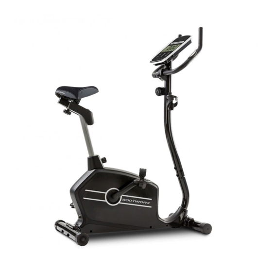
- Page 1 MANUAL TENSION UPRIGHT BIKE Model No: ABX250M Retain this owner’s manual for future reference. Read and follow all instructions in this owner’s manual.
- Page 2 Warranty Registration Form Congratulations on purchasing your product, we at GPI believe that our product range is of the highest quality and represents great value for money. We back our product range up with our industry leading warranty. Please see below for the step by step instructions on how to register your product warranty online.
- Page 3 CONTENT PAGE ??????? ??????? ??????? ??????? ??????? ??????? ??????? ???????
-
Page 4: Important Safety Instructions
IMPORTANT SAFETY INSTRUCTIONS Before beginning any fitness program, you should obtain a complete physical examination from your physician. This exercise equipment is designed and built for optimum safety for home use. However, certain precautions always apply whenever you operate any exercise equipment. Be sure to read the entire manual before assembly and operation of this machine. -
Page 5: Safety Guidelines
SAFETY GUIDELINES Successful fitness training programs have one prominent feature in common...safety. Fitness training has some inherent dangers, as do all physical activities. The chance of injury can be greatly reduced or completely removed by using correct techniques, proper breathing, maintaining equipment in good working condition, and by wearing the appropriate clothing. -
Page 6: Parts List
PARTS LIST Part No. Description Part No. Description Main frame Cover for sliding tube Front stabiliser Club knob Rear stabiliser Cover for clamp Front post Crank (L/R) Handlebar Bushing Computer Self-tapping screw ST5*15 Seat post Magnet assembly Seat Chain cover L/R Pedal (Left) Cover for chain cover Pedal (Right) -
Page 7: Exploded Diagram
EXPLODED DIAGRAM... -
Page 9: Hardware Parts List
HARDWARE PARTS LIST HARDWARE PARTS LIST Description Drawing Q’ty Quick release knob Spring washer Φ8 Allen bolt M8*75 Curved washer Φ8*Φ20 Allen bolt M8*16 T-type knob Cover for clamp Box wrench Allen key 6mm The above described parts are all the parts you need to assemble this machine. Before you start assembly, please check the hardware pack to make sure they are included. -
Page 10: Pre-Assembly Check List
PRE-ASSEMBLY CHECK LIST PRE-ASSEMBLY CHECK LIST NO:1 NO:4 NO:7 NO:35 NO:5 NO:6 NO:9/10 NO:19 NO:2 NO:3 NO:8 NO:17 PART NO. DESCRIPTION Q’TY Main frame Front stabiliser Rear stabiliser Front post Handlebar Computer Seat post Seat Pedal (Left) Pedal (Right) Seat post cover Bottle holder Cover for sliding tube User manual... -
Page 11: Assembly Instruction
ASSEMBLY INSTRUCTION ASSEMBLY INSTRUCTION STEP 1 ⚫ Attach Front stabiliser (2) to Main frame (1), tighten with 2 sets of Allen bolt (15), Spring washer (13) and Curved washer (16). ⚫ Attach Rear stabiliser (3) to Main frame (1), tighten with 2 sets of Allen bolt (15), Spring washer (13) and Curved washer (16). -
Page 12: How To Connect Tension Connector
HOW TO CONNECT TENSION CONNECTOR Slide the Cable wire from the Upper tension connector in between the opening on the wire holder on the Lower tension connector. Pull the Upper Tension Connector backward and slide the wire through the slot on the bracket. - Page 13 STEP 3 ⚫ Remove the Clamp (25) and Allen bolt (22) from Front post (4). Attach Handlebar (5) to Front post (4) and Tighten with Clamp (25), Allen bolt (22), Cover for clamp (37) and T-type knob (21). ⚫ Insert Hand pulse wires (20) into the Grommet (32) and pull out from top bracket. ⚫...
- Page 14 STEP 5 ⚫ The left and right Pedals (9 & 10) are marked “L” & “R”. Attach straps to the pedals. Connect left Pedal (9) to the Crank (38). The left Pedal (9) is on the left-hand side of the cycle as you sit on it.
-
Page 15: Console Instructions
CONSOLE INSTRUCTIONS COMPUTER INSTRUCTION Button: 1.BODY FAT: Press the key to enter your personal data before measure your body fat ratio. 2.MEASURE: Press the key to enter the body fat test mode. The user holds the grips tightly with both hands for about 30 seconds. The computer will automatically display the user's fat value (FAT%, BMI and BMR). -
Page 16: Exercise Instructions
EXERCISE INSTRUCTIONS Using your exerciser will provide you with several benefits, it will improve your physical fitness, tone muscle and in conjunction with a calorie controlled diet help you lose weight. 1. THE WARM UP PHASE This stage helps get the blood flowing around the body and the muscles working properly. It will also reduce the risk of cramp and muscle injury. -
Page 17: Muscle Toning
EXERCISE INSTRUCTIONS 3. THE COOL DOWN PHASE This stage is to let your Cardio Vascular System and muscles wind down. This is a repeat of the warm up exercise e.g. reduce your tempo, continue for approximately 5 minutes. The stretching exercises should now be repeated, again remembering not to force or jerk your muscles into the stretch. - Page 18 MANUAL TENSION UPRIGHT BIKE Model No: ABX250M To register your warranty, please go to www.gpisports.com.au DISTRIBUTED EXCLUSIVELY BY 275 Wellington Road Mulgrave, VIC, 3170 Australia...
Need help?
Do you have a question about the ABX250M and is the answer not in the manual?
Questions and answers