
Subscribe to Our Youtube Channel
Related Manuals for Bodyworx MAG BIKE ABK2.0


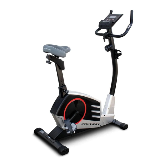
Summary of Contents for Bodyworx MAG BIKE ABK2.0
- Page 1 MANUAL MAG BIKE Model No: ABK2.0 Retain this owner’s manual for future reference. Read and follow all instructions in this owner’s manual.
-
Page 2: Table Of Contents
CONTENT PAGE IMPORTANT SAFETY INSTRUCTIONS SAFETY GUIDELINES PARTS LIST EXPLODED DIAGRAM HARDWARE PARTS LIST PRE-ASSEMBLY CHECK LIST ASSEMBLY INSTRUCTIONS 10-13 CONSOLE INSTRUCTIONS 14-15 EXERCISE INSTRUCTIONS 16-17... -
Page 4: Important Safety Instructions
IMPORTANT SAFETY INSTRUCTIONS Before beginning any fitness program, you should obtain a complete physical examination from your physician. This exercise equipment is designed and built for optimum safety for home use. However, certain precautions always apply whenever you operate any exercise equipment. Be sure to read the entire manual before assembly and operation of this machine. -
Page 5: Safety Guidelines
SAFETY GUIDELINES Successful fitness training programs have one prominent feature in common...safety. Fitness training has some inherent dangers, as do all physical activities. The chance of injury can be greatly reduced or completely removed by using correct techniques, proper breathing, maintaining equipment in good working condition, and by wearing the appropriate clothing. -
Page 6: Parts List
PARTS LIST PART LIST Part No. Description Part No. Description Main frame Self tapping screw Front stabiliser Square end cap 38*38 Rear stabiliser Washer Front post Bolt M5 Handlebar Lower Tension Cable Computer Chain cover L/R Seat post Cover for chain cover Seat Flange screw Pedal (L) -
Page 7: Exploded Diagram
EXPLODED DIAGRAM EXPLODED DIAGRAM 76 54 62 63 64 65 72 73 66 67 60 61 46 47... -
Page 8: Hardware Parts List
HARDWARE PARTS LIST HARDWARE PARTS LIST The below described parts are all the parts you need to assemble this machine. Before you start assembly, please check the hardware pack to make sure they are included. Please note NO.11 & 37 is packed into a small bag which is attached behind the hardware pack. M8*16mm 20mm M8*55mm... -
Page 9: Pre-Assembly Check List
PRE-ASSEMBLY CHECK LIST PRE-ASSEMBLY CHECK LIST 9/10 PART NO. DESCRIPTION Main frame Front stabiliser Rear stabiliser Front post Handlebar Computer Seat post Seat Left pedal Right pedal Cover for sliding tube Seat post cover Cover for front post Bottle holder User manual Hardware pack... -
Page 10: Assembly Instructions
ASSEMBLY INSTRUCTIONS ASSEMBLY INSTRUCTION STEP 1 Attach front stabiliser (2) to main frame (1), tighten with 2 sets of allen bolt (15), curved washer (16) and spring washer (19). Attach rear stabiliser (3) to main frame (1), tighten with 2 sets of allen bolt (15), curved washer (16) and ... - Page 11 HOW TO CONNECT TENSION CONNECTOR Slide the Cable wire from the Upper Tension Connector in between the opening on the wire holder on the Lower Tension Connector. Pull the Upper Tension Connector backward and slide the wire through the slot on the bracket. Drop down the Connector so the fitting sits firmly on top of the bracket.
- Page 12 STEP 3 Remove the clamp (25) and allen bolt (22) from front post (4). Attach handlebar (5) to front post (4) and tighten with clamp (25), allen bolt (22), cover for clamp (37) and T-type knob (21). Insert hand pulse wires (20) into the grommet (32) and pull out from top bracket. Attach hand pulse wires (20) ...
- Page 13 STEP 5 The left and right pedals (9 & 10) are marked “L” & “R”. Attach straps to the pedals. Connect left pedal (9) to the crank (48). The left pedal is on the left hand side of the cycle as you sit on it. Repeat for the right pedal (10).
-
Page 14: Console Instructions
CONSOLE INSTRUCTIONS COMPUTER INSTRUCTION FUNCTIONAL BUTTONS: MODE: Push down for selecting functions. SET: To Set the consumer movement of time, distance, calories and hand pulse. RESET: For resetting consumer movement of time, distance, calories and hand pulse. FUNCTION AND OPERATIONS: SCAN: Press "MODE"... - Page 15 SPECIFICATIONS: AUTO SCAN Every 6 seconds TIME 0:00’~99:59’ CURRENT 0.0~999.9 KM/H(MILE/H) SPEED FUNCTION TRIP DISTANCE 0.00~999.9 KM (MILE) CALORIES 0.0~999.9 CAL ODOMETER 0.0 ~ 9999 KM(MILE) PULSE RATE 40~240 BPM BATTERY TYPE 2pcs of SIZE –AA or UM –3 OPERATING TEMPERATURE 0°C ~ +40°C STORAGE TEMPERATURE -10°C ~ +60°C...
-
Page 16: Exercise Instructions
EXERCISE INSTRUCTIONS Using your exerciser will provide you with several benefits, it will improve your physical fitness, tone muscle and in conjunction with a calorie controlled diet help you lose weight. 1. THE WARM UP PHASE This stage helps get the blood flowing around the body and the muscles working properly. It will also reduce the risk of cramp and muscle injury. - Page 17 EXERCISE INSTRUCTIONS 3. THE COOL DOWN PHASE This stage is to let your Cardio Vascular System and muscles wind down. This is a repeat of the warm up exercise e.g. reduce your tempo, continue for approximately 5 minutes. The stretching exercises should now be repeated, again remembering not to force or jerk your muscles into the stretch.
- Page 18 MANUAL MAG BIKE Model No: ABK2.0 To register your warranty, please go to www.gpisports.com.au DISTRIBUTED EXCLUSIVELY BY 275 Wellington Road Mulgrave, VIC, 3170 Australia...
Need help?
Do you have a question about the MAG BIKE ABK2.0 and is the answer not in the manual?
Questions and answers