
Related Manuals for Bodyworx AIC850


Summary of Contents for Bodyworx AIC850
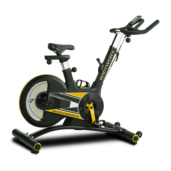
- Page 1 REAR DRIVE INDOOR CYCLE Model No: AIC850 Retain this owner’s manual for future reference. Read and follow all instructions in this owner’s manual.
-
Page 3: Table Of Contents
CONTENT PAGE IMPORTANT SAFETY INSTRUCTIONS SAFETY GUIDELINES PARTS LIST EXPLODED DIAGRAM HARDWARE PARTS LIST PRE-ASSEMBLY CHECK LIST ASSEMBLY INSTRUCTION 10-14 CONSOLE INSTRUCTIONS 15-17 EXERCISE INSTRUCTIONS 18-19... -
Page 4: Important Safety Instructions
IMPORTANT SAFETY INSTRUCTIONS Before beginning any fitness program, you should obtain a complete physical examination from your physician. This exercise equipment is designed and built for optimum safety for home use. However, certain precautions always apply whenever you operate any exercise equipment. Be sure to read the entire manual before assembly and operation of this machine. -
Page 5: Safety Guidelines
SAFETY GUIDELINES Successful fitness training programs have one prominent feature in common...safety. Fitness training has some inherent dangers, as do all physical activities. The chance of injury can be greatly reduced or completely removed by using correct techniques, proper breathing, maintaining equipment in good working condition, and by wearing the appropriate clothing. -
Page 6: Parts List
PARTS LIST Description Description Left pedal Chain cover L Right pedal Decorative strip End cap of stabiliser Axle for crank Carriage bolt M10*90 Long bushing for crank Rear stabiliser Short bushing for crank Curved washer φ10 Chain cover R Domed nut M10 Belt Ball type quick release knob Belt-drive wheel... -
Page 7: Exploded Diagram
EXPLODED DIAGRAM Self-tapping screw 3 EXPLODED DIAGRAM... -
Page 8: Hardware Parts List
HARDWARE PARTS LIST HARDWARE PARTS LIST HARDWARE PACK Inner hexagon spanner (5#) Crosshead spanner Part No Description Carriage bolt M10*90 Curved washer φ10 Domed nut M10 Ball type quick release knob L type quick release knob Ball type knob Cross head spanner Spanner Inner hexagon spanner Silicon oil... -
Page 9: Pre-Assembly Check List
PRE-ASSEMBLY CHECK LIST PRE-ASSEMBLY CHECK LIST PART NO. DESCRIPTION Left Pedal Right Pedal Rear stabiliser 10/12/21/77/78 Seat post assembly Seat Front stabiliser Main frame Handlebar post Handlebar Bottle holder Computer Hardware pack User manual... -
Page 10: Assembly Instruction
ASSEMBLY INSTRUCTION ASSEMBLY INSTRUCTION Step 1 Attach the front stabiliser (15) to the main frame (16). Secure using two carriage bolts (3), two curved washers (5) and two domed nuts (6). Attach the rear stabiliser (4) to the main frame (16). Secure using two carriage bolts (3), two curved washers (5) and two domed nuts (6). - Page 11 Step 2 Release the nuts on the backside of seat (13), attach the seat (13) to sliding tube and then re-tighten the nuts. Insert the seat post (10) into the Main frame (16). Secure using a ball type quick release knob (7).
- Page 12 Step 3 Insert the handlebar post (17) to the main frame (16). Secure using an L type quick release knob (19). Attach the handlebar (18) to the handlebar post (17). Secure using a ball type knob (22). Attach computer (72) onto the computer bracket and secure using 4 screws (73) which are pre-assembled on the backside of computer (72).
- Page 13 Step 4 Attach the left pedal (1L) to the left crank (33). Attach the right pedal (1R) to the right crank (36). Note: The right pedal should be threaded on clockwise and the left pedal on counter-clockwise. ENSURE THAT ALL BOLTS AND NUTS ARE TIGHTENED BEFORE USING THE MACHINE...
- Page 14 ADJUSTING THE TENSION Turn the tension knob (63) up or down to adjust the tension. LUBRICATION Lubrication is a highly important service activity for the Sprinter bike ASB650. This is absolutely essential, if the friction of the brake system increases noticeably. Increased friction is indicated by jerky movement in higher resistance levels.
-
Page 15: Console Instructions
CONSOLE INSTRUCTIONS COMPUTER INSTRUCTIONS FUNCTION BUTTON MODE/RESET: To confirm all settings. Press this button and hold for 2 seconds to reset all function figures. SET: To set up the value of TIME, DISTANCE, CALORIES, PULSE. You can hold the button to increase the value fast. (The computer has to be in stop condition.) FUNCTION: RPM: Displays the pedaling Rotation Per Minute. - Page 16 OPERATION PROCEDURE: 1. Installs 1 piece of CR2032 3V battery, then the screen will display as following “Drawing A” and have a “bi” sound at the same time. After that, it goes to the next step to the main menu as “Drawing B”. 2.Get access to the set-up mode of TIME/DISTANCE/CALORIES/PULSE.
- Page 17 Battery replacement instruction: 1. Holding up the Clip on the side of the battery cover. 2. Remove the cover. Install a new CR2032 battery by tilting the battery slightly to its side and slide it in (positive+ at upper side and negative- at down side). 4.
-
Page 18: Exercise Instructions
EXERCISE INSTRUCTIONS Using your exerciser will provide you with several benefits, it will improve your physical fitness, tone muscle and in conjunction with a calorie controlled diet help you lose weight. 1. THE WARM UP PHASE This stage helps get the blood flowing around the body and the muscles working properly. It will also reduce the risk of cramp and muscle injury. - Page 19 EXERCISE INSTRUCTIONS 3. THE COOL DOWN PHASE This stage is to let your Cardio Vascular System and muscles wind down. This is a repeat of the warm up exercise e.g. reduce your tempo, continue for approximately 5 minutes. The stretching exercises should now be repeated, again remembering not to force or jerk your muscles into the stretch.
- Page 20 REAR DRIVE INDOOR CYCLE Model No: AIC850 To register your warranty, please go to www.gpisports.com.au DISTRIBUTED EXCLUSIVELY BY 275 Wellington Road Mulgrave, VIC, 3170 Australia...
Need help?
Do you have a question about the AIC850 and is the answer not in the manual?
Questions and answers