Advertisement
Quick Links
Advertisement

Related Manuals for Bodyworx ABW300


Summary of Contents for Bodyworx ABW300
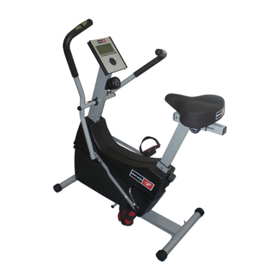
- Page 1 OWNER’S MANUAL DUAL ACTION BIKE...
-
Page 2: Table Of Contents
Table of Contents Important Safety Information Before You Start Assembly Instruction 5-15 Console Overview 16-17 Monitoring Your Heart Rate 18-20 Exploded View Parts List 22-23 (0108UT6706-07) -
Page 3: Important Safety Information
Important Safety Information WARNING! Before using this unit or starting any exercise program, consult your physician. This is especially important for persons over the age of 35 and/or persons with pre-existing health problems. The manufacturer or distributor assumes no responsibility for personal injury or property damage sustained by or through the use of this product. -
Page 4: Before You Start
Before You Start Thank you for purchasing this new Dual Action Bike! This quality product you have chosen was designed to meet your needs for cardiovascular exercise. Before you start, please read the Owner's Manual and become familiar with the operation of your new unit. Remember to take the time to perform the stretching exercises provided to avoid injury. -
Page 5: Assembly Instruction
Assembly Instruction REMOVE ALL SECURITY TAPE AND WRAPPING BEFORE BEGINNING FIGURE 1 STEP 1. Attach Foot Tube (27) to front of Main Frame (1) using : Qty 2 – (43) Carriage Bolt Qty 2 – (67) Black Washer Qty 2 – (45) Nut Cap Make sure that the Foot Tube (27) with Wheels (28) are assembled to the front of the Main Frame (1). - Page 6 Assembly Instruction FIGURE 2 Step 1: Slide Pedal Bushing (54) onto shafts of Pedals (40&41) as showed as diagram. Then thread Shafts of Pedals (40&41) into Crank (10) until tight ,then back off 1/2 turn. Step 2: Thread Pedal Locknut(42) onto end of Shaft. Hold Shaft with (additional wrench) and tighten Pedal Locknut(42) with other wrench until tight.
- Page 7 Assembly Instruction FIGURE 3 Turn Locking Knob (32) counterclockwise to loosen. Slide the Seat Post (30) into Main Frame (1) and secure with Locking Knob (32). * IMPORTANT Locking Knob (32) must be locked tightly into hole in Seat Post (30) before you sit on the seat.
- Page 8 Assembly Instruction FIGURE 4 Step 1: Attach Seat (31) to the Seat Post Slider (89) with the Nuts (82) and Flat Washer (81) already provided on the underside of Seat. Step 2: a. Turn Seat Adjustment Knob (87) counterclockwise to loosen. b.
- Page 9 Assembly Instruction FIGURE 5 Step 1 : Connect the Extension Wire (50) in the Console Tube (2) to the Reed Switch Wire (52) in the Main Frame (1) . Step 2: Connect the tension cable(71) in the Console Tube to the Tension Cable Bracket(57) in the main frame.
- Page 10 Assembly Instruction FIGURE 6 Step 1: With Pivot Tubes on rear side of Handlebars (35& 36) and Connecting Arms (38&39) to inside, slide one Large Washer (75) and Handlebars(35 & 36) onto Axle as showed. Step 2: Slide M17 Washer (58) onto end of Axle and carefully tap Push nut (47) onto end of Axle with hammer.
- Page 11 Assembly Instruction FIGURE 7 (The following steps are for DUAL ACTION MODE) Step 1: Slide Retainers (49) onto Connecting Arms(38&39) until it has cleared SLOT in Connecting Arms as showed . Lower Slot in Connecting Arms down over Pedal Bushing.-see FIGURE “ A” Step 2: Slide Retainer until Connecting Arms are locked in Dual Action Mode.-see FIGURE “B”...
- Page 12 Assembly Instruction FIGURE 8 (The following steps are for SINGLE ACTION MODE) Lower slot in Connecting Arms(38& 39) onto Lockout Rod and slide Retainer (49) back over Lockout Rod to lock Connecting Arm(38& 39) in Single Action Mode. FIGURE 8 LOCKOUT ROD -12-...
- Page 13 Assembly Instruction FIGURE 9 Insert the batteries provided into the back of the Monitor(3) -13-...
- Page 14 Assembly Instruction FIGURE 10 Step 1: Connect the Pulse Extension Wires (51) and Extension Wire (50) to Monitor (3). Secure Monitor(3) to Console Tube using four Screws (7). Note: The four Screws(7) will already be installed into the back of Monitor (3) when you remove it from the box.
- Page 15 Assembly Instruction Congratulations! You have completed the assembly of your new Dual Action Bike ! -15-...
-
Page 16: Console Overview
Console Overview EXERCISE MONITOR INSTRUCTION MANUAL FRONT VIEW FUNCTION SPD:0.0~99.9 KM TIME:0:00~99:59. Up count/Down count are available. DIST: 0.00~99.99 K. Up count/Down count are available. CAL: 0~9999. Up count/Down count are available. PULSE: P~30~240,max value is available. TEMP: ℃ (0~60℃) DATE: 1900/1/1~2006/1/1~2099/12/31 CLOCK: 24 hours 0:00~23:59 OPERATION METHOD... - Page 17 4. Recovery: (1) After pressing recovery key, recovery function will start, only pulse and time are able to use, other functions disable to use and display off, sensor input is effective. TIME display “1:00” , LCD begin to count down, heart beat signal will blink with heart beat. Other parts display off. (2) LCD display as recovery mode &...
-
Page 18: Monitoring Your Heart Rate
Monitoring Your Heart Rate Monitoring Your Heart Rate To obtain the greatest cardiovascular benefits from your exercise workout, it is important to work within your target heart rate zone. The American Heart Association (AHA) defines this target as 60%-75% percent of your maximum heart rate. Your maximum heart rate may be roughly calculated by subtracting your age from 220. - Page 19 Monitoring Your Heart Rate Fitness Safety The target heart rate chart indicates average rate zones for different ages. A variety of different factors (including medication, emotional state, temperature and other conditions) can affect the target heart rate zone that is best for you.
- Page 20 Monitoring Your Heart Rate -20-...
-
Page 21: Exploded View
Exploded View -21-... -
Page 22: Parts List
Parts List ITEM Q’TY PART NAME ITEM Q’TY PART NAME Frame Right Pedal Console Tube Right Pedal Strap Monitor Left Pedal Hand Pulse Grip w/Wire Left Pedal Strap Handlebar Sleeve 1/2” Nut M4x25mm Screw M8x55mm Carriage Bolt M5x10mm Screw Adjustment Channel Bearing Cup M8 Nut Cap Bearing... - Page 23 M24x38mm Washer 38x45mm Left Inner Bushing TP 3x8mm Screw 38x45mm Right Inner Bushing M8x12.5x14.9L Spacer 38x45mm Rear Inner Bushing 6mm Hex Nut Seat Adjustment Knob (22mml) M8x19mm Washer (Zinc) 38x38mm Plastic Inner Bushing 8mm Locknut Seat Post Slider Connecting Arm Bushing -23-...
Need help?
Do you have a question about the ABW300 and is the answer not in the manual?
Questions and answers