Table of Contents
Advertisement
Quick Links
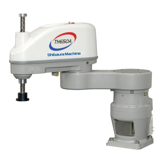
TH650A/TS3100
MAINTENANCE MANUAL
1.
Make sure that this instruction manual is delivered to the final
user of Toshiba Machine's industrial robot.
2.
Before operating the industrial robot, read through and
completely understand this manual.
3.
After reading through this manual, keep it nearby for future
reference.
Notice
October, 2010
TOSHIBA MACHINE CO., LTD.
NUMAZU, JAPAN
STE 85306–3
Advertisement
Table of Contents

Related Manuals for Toshiba TH650A


Summary of Contents for Toshiba TH650A
- Page 1 MAINTENANCE MANUAL Notice Make sure that this instruction manual is delivered to the final user of Toshiba Machine's industrial robot. Before operating the industrial robot, read through and completely understand this manual. After reading through this manual, keep it nearby for future reference.
- Page 2 MAINTENANCE MANUAL Copyright 2007 by Toshiba Machine Co., Ltd. All rights reserved. No part of this document may be reproduced in any form without obtaining prior written permission from Toshiba Machine Co., Ltd. The information contained in this manual is subject to change without notice to effect improvements.
- Page 3 MAINTENANCE MANUAL WARRANTY This machine is delivered to each customer only after it is inspected very carefully to make sure that it satisfies the Toshiba Machine’s standard. Should it cause an inconvenience, we will guarantee as described below. Warranty period Toshiba Machine agrees to repair or replace as necessary all defective material or workmanship up to the period shown below, whichever comes first.
- Page 4 Please note that the warnings, cautions and other descriptions stipulated in this manual are only those which can be assumed by Toshiba Machine as of now. STE 85306 – 4 –...
- Page 5 MAINTENANCE MANUAL INTRODUCTION This manual describes the TH650A industrial robot and TS3100 controller. The maintenance and inspection are essential to maintain the robot performance for long years to prevent a trouble and improve the safe work. Before starting an actual operation, it is strongly recommended to read through this manual and draw up a maintenance schedule.
- Page 6 MAINTENANCE MANUAL [Explanation of symbols] Symbol Meaning of symbol This means that the action is prohibited (must not be done). Details of the actions actually prohibited are indicated with pictures or words in or near the symbol. This means that the action is mandatory (must be done). Details of the actions that must be done are indicated with pictures or words in or near the symbol.
- Page 7 Disassembly prohibited • Always use the Toshiba Machine's designated spare parts when replacing the parts. • Maintenance and inspection should be performed regularly. Mandatory Otherwise, the system may malfunction or accidents will be caused.
-
Page 8: Table Of Contents
MAINTENANCE MANUAL Table of Contents Page Maintenance ......................11 Maintenance Schedule .................. 11 Items for Maintenance and Inspection ............12 1.2.1 Inspection at Power OFF (at Non-Operation) ........12 1.2.2 Inspection at Power ON (at Operation) ..........13 1.2.3 Overhaul .................... 13 Maintenance Tools .................. - Page 9 MAINTENANCE MANUAL 2.5.9 Dismounting Axis 4 Motor ..............44 2.5.10 Mounting Axis 4 Motor ..............45 Adjusting and Replacing Timing Belt ............. 46 2.6.1 Type of Timing Belt ................46 2.6.2 Timing Belt Locations ................ 47 2.6.3 Replacing Axis 3 Timing Belt............. 47 2.6.4 Replacing Axis 4 Timing Belt.............
- Page 10 MAINTENANCE MANUAL Robot Home Point and Position Detector Error ............94 Setting Robot Home Point ................94 Position Detector Error .................. 95 Restoring Operation from Position Detector Error ......... 98 4.3.1 Encoder Status Display ..............98 4.3.2 Encoder Error Reset Operation ............100 Restoring Home Position Data by HOME Function ........
-
Page 11: Maintenance
MAINTENANCE MANUAL Maintenance Maintenance Schedule Maintenance comes in the two (2) types; daily inspection, and regular inspection and maintenance. For the regular inspection and maintenance, inspection items are added every 1,200 running hours. 3-month 1200 check 3-month 6-month 2400 check check 3-month 3600... -
Page 12: Items For Maintenance And Inspection
MAINTENANCE MANUAL Items for Maintenance and Inspection This section describes the items for maintenance and inspection. For the executing procedures, see the relevant paragraph listed in the table below. 1.2.1 Inspection at Power OFF (at Non-Operation) D: Daily inspection Q: Quarterly inspection S: Semi-annual inspection A: Annual inspection Description... -
Page 13: Inspection At Power On (At Operation)
MAINTENANCE MANUAL 1.2.2 Inspection at Power ON (at Operation) D: Daily inspection Q: Quarterly inspection S: Semi-annual inspection A: Annual inspection Description Check position Refer to Push each arm by hand in Each joint the servo ON condition to make sure that the arm is secured. -
Page 14: Maintenance Tools
If a fault has occurred or if repair is necessary, turn off the controller power and contact the Toshiba Machine Service Department. At this time, advise us of the details of the fault and the following information stated on the robot and controller. -
Page 15: Modification
1.4.3 Modification The robot and controller MUST NOT be modified or disassembled without a prior consent from Toshiba Machine. CAUTION • The user must NEVER replace or modify parts other than those described in the instruction manual. -
Page 16: Maintenance Of The Main Robot
MAINTENANCE MANUAL Maintenance of the Main Robot Cautions on Maintenance and Inspection When performing inspection or maintenance of the robot, strictly observe the following precautions to protect yourself and coworkers. DANGER • Be sure to turn off the main power switch of the controller before approaching the robot for maintenance and inspection. - Page 17 MAINTENANCE MANUAL For the screws arranged on a circle for mounting the reduction gear, etc., tighten them in the diagonal order, as shown below. DO NOT tighten one (1) screw at a time. Tighten each screw in multiple steps, using a hexagonal wrench key, and secure with appropriate clamping torque by means of a torque wrench.
-
Page 18: Details Of Inspection
MAINTENANCE MANUAL Details of Inspection 2.2.1 Check of Each Bolt (or Screw) for Clamping Tool Set Bolts Make sure, using the hexagonal wrench key, that the hexagon socket head cap screws of the tool set flange, which are clamped to the tool shaft are tightened completely. - Page 19 MAINTENANCE MANUAL Main robot installation bolt M16 x 4 pcs.; Recommended clamping torque 170 N·m Fig. 2.2 Robot base set bolts Bolts for each joint Make sure, using the hexagonal wrench key, that the bolts for the axis 1 and 2 joints (i.e., bolts for clamping each reduction gear and arm) are tightened completely.
- Page 20 MAINTENANCE MANUAL Motor Set Bolts Make sure, using the hexagonal wrench key, that the bolts for securing each axis drive motor are tightened completely. If loosened, tighten them completely. Also make sure that the motor base set bolts are tightened completely. For the places where the following bolts are used, see Para.
-
Page 21: Check Of Each Connector For Clamping
MAINTENANCE MANUAL 2.2.2 Check of Each Connector for Clamping Make sure that the cable connectors connected to the robot main base are tightened completely. If loosened, tighten them completely. Turn each cable connector by hand and make sure that it is tightened completely. -
Page 22: Check Of Each Axis For Operation
MAINTENANCE MANUAL 2.2.4 Check of Each Axis for Operation Turn on the main power switch of the controller, then keep the EMERGENCY pushbutton switch in the depressed condition. Move each axis by hand and make sure that it can move smoothly. For the axes 3 and 4, when the brake OFF pushbutton switch is pressed, the brake is released. -
Page 23: Layout Of Robot Components And Drive Mechanism
MAINTENANCE MANUAL Layout of Robot Components and Drive Mechanism The layout of the robot mechanical components is shown in Fig. 2.6. Axis 4 reduction gear Axis 4 drive motor Axis 2 Axis 3 drive motor Ball screw drive motor spline shaft Axis 3 timing belt Axis 1... - Page 24 MAINTENANCE MANUAL Axis 3 The axis 3 AC servo motor is mounted on the axis 2 arm. The motor revolution is input to the ball screw nut through the timing belt to move the ball screw spline up and down. Axis 4 The axis 4 AC servo motor is mounted on the axis 2 arm.
-
Page 25: Dismounting And Mounting Each Cover
MAINTENANCE MANUAL Dismounting and Mounting Each Cover This paragraph describes the dismounting and mounting of the covers, which are common to the maintenance and replacement of each unit. DANGER • When opening the cover, take careful precautions not to allow entry of moisture or contaminant into the robot. -
Page 26: Arm 2 Cover
MAINTENANCE MANUAL 2.4.1 Arm 2 Cover The arm 2 cover is secured to the cover set bracket with four (4) cross truss head screws (M4 × 10). As the arm 2 cover is inserted into the arm 2, it can be lifted once the screws are removed. -
Page 27: Arm 1 Covers
MAINTENANCE MANUAL 2.4.2 Arm 1 Covers The arm 1 covers are provided on top of the axis 1 (arm cover 1) and under the axis 2 (arm cover 2). Each cover is secured to the arm 1 with six (6) cross truss head screws (M4 ×... - Page 28 MAINTENANCE MANUAL Packing Hexagon socket head cap screws Cross truss head screw Cross truss Cover also used as Cover also serving as head screw battery box cover connector panel cover Fig. 2.9 Base covers STE 85306 – 28 –...
-
Page 29: Replacing Motor
MAINTENANCE MANUAL Replacing Motor The motor is to be replaced by our service engineer. If it is replaced by the customer, we will not guarantee any consequential trouble or accident. DANGER • The motor should be replaced with a new one only after the controller power is turned off with the power supply plug removed. -
Page 30: Type Of Motor
Type of Motor The motors employed in this robot are shown below. When you place an order for a new motor, make sure of the robot model (TH650A), axis name, type and our drawing number according to the following table. -
Page 31: Motor Locations
MAINTENANCE MANUAL 2.5.2 Motor Locations Axis 4 motor Axis 2 motor Axis 3 motor Axis 1 motor Fig. 2.10 Motor locations STE 85306 – 31 –... -
Page 32: Dismounting Axis 1 Motor
MAINTENANCE MANUAL 2.5.3 Dismounting Axis 1 Motor Disconnect the two (2) covers attached to the base. (See Para. 2.4.3.) Disconnect connectors J1AS and J1AP (power drive cables) and connectors J1BS and J1BP (encoder cables) of the axis 1 motor. Remove the four (4) bolts (M5 × 25) securing the motor base, then draw the motor downward. -
Page 33: Mounting Axis 1 Motor
MAINTENANCE MANUAL Tap for disassembly (M4; 2 places) M5x10 Washer Motor base Input gear “O” ring Washer M5x20 Remove the four (4) bolts (M5 × 20) securing the motor. Disengage the motor from the motor base. As the motor set surface is applied with liquid gasket, disengage them, using the taps for disassembly (M4, two (2) places). - Page 34 MAINTENANCE MANUAL CAUTION • When mounting the input gear, DO NOT knock it with excessive force. Otherwise, the encoder may be damaged. M5x10 (Recommended clamping torque: 8.8 N·m) Washer Surface where liquid gasket is to be applied. Input gear “O” ring Washer M5x20 (Recommended clamping torque: 8.8 N·m)
-
Page 35: Dismounting Axis 2 Motor
MAINTENANCE MANUAL CAUTION • Be sure to mount the “O” ring and apply the liquid gasket. Otherwise, grease will leak from the motor base set surface. 2.5.5 Dismounting Axis 2 Motor Disconnect the arm 2 cover. (See Para. 2.4.1.) Cut the TY-RAP for the cables secured to the cover bracket, using nippers, etc., and remove the four (4) cross truss head screws (M4 ×... - Page 36 MAINTENANCE MANUAL Draw out the cables and air tubes thus disconnected up to the upper side of the arm 2. As the inner diameter of the center shaft is small, observe the following order, taking careful precautions not to damage the cables and connectors when disconnecting the cables.
- Page 37 MAINTENANCE MANUAL M6x35 Bearing 6807 “O” ring Tension adjustment Input gear Axis 2 gear case bolt (M4x35) The taps (M5) for maintenance are provided on the input gear. Secure the input gear, using them and remove the bolt (M6 × 8) at the shaft end. Draw the input gear and key upward.
-
Page 38: Mounting Axis 2 Motor
MAINTENANCE MANUAL 2.5.6 Mounting Axis 2 Motor Perform key alignment, using the new motor and input gear. At this time, no clearance should exist between the motor shaft and input gear. CAUTION • Perform key alignment very carefully. If there is a clearance between the motor shaft and input gear, an abnormal noise may be heard at the time of operation. - Page 39 MAINTENANCE MANUAL CAUTION • Be sure to attach the “O” ring and apply the liquid gasket. Otherwise, grease will leak from the gear case set surface and motor set surface. Attach the gear case to the arm 2 with six (6) bolts (M6 × 35). Make sure that the center gear of the axis 2 reduction gear is mounted.
- Page 40 MAINTENANCE MANUAL Cover bracket Connector panel Connect the axis 2 motor connectors (for power drive cable and encoder cable). Return the cables in the arm 2 as originally arranged, then attach all covers. After the axis 2 motor is replaced with a new one and before the power is turned on, move the arm 2 by hand to make sure that no abnormal noise is heard.
-
Page 41: Dismounting Axis 3 Motor
MAINTENANCE MANUAL 2.5.7 Dismounting Axis 3 Motor CAUTION • The axis 3 motor is provided with a brake. At replacement of the axis 3 motor, this brake becomes inoperative. Before starting the work, therefore, move down the ball screw spline to the lower limit. Otherwise, the shaft will drop due to the dead weight of the shaft or workpiece, and your hand or finger may be caught. -
Page 42: Mounting Axis 3 Motor
MAINTENANCE MANUAL Washer M4x8 Axis 3 motor pulley Axis 3 motor base Washer M4x16 2.5.8 Mounting Axis 3 Motor Perform key alignment, using the new motor and input gear. At this time, no clearance should exist between the motor shaft and pulley. CAUTION •... - Page 43 MAINTENANCE MANUAL Temporarily clamp the motor base to the arm 2 with four (4) flange head bolts (M5 × 16). Pass the axis 3 timing belt to the axis 3 motor pulley, then exert a tension, using the axis 3 tension adjustment bolt (M4 × 35). (For the belt replacement procedures and tension adjustment value, see Para.
-
Page 44: Dismounting Axis 4 Motor
MAINTENANCE MANUAL 2.5.9 Dismounting Axis 4 Motor Remove the arm 2 cover. (See Para. 2.4.1.) Disconnect connectors J4AS and J4AP (power drive cables) and connectors J4BS and J4BP (encoder cables) of the axis 4 motor. For the connector layout, see Para. 2.5.7. Remove the cap attached to the lateral side of the axis 4 reduction gear and loosen the coupling bolt (M4 ×... -
Page 45: Mounting Axis 4 Motor
MAINTENANCE MANUAL 2.5.10 Mounting Axis 4 Motor Mount the new motor on the axis 4 reduction gear with four (4) bolts (M4 × 16). Tighten the coupling of the axis 4 reduction gear by means of the attached bolt (M4 × 12) to mount the cap. (Recommended clamping torque: 4.7 N·m) M4×16 (Recommended clamping torque: 4.7 N·m) Washer... -
Page 46: Adjusting And Replacing Timing Belt
Type of Timing Belt The timing belts used in this robot are shown below. When you place an order for the timing belt for replacement, specify the robot model (TH650A), axis name, type and our drawing number. Description Axis name... -
Page 47: Timing Belt Locations
MAINTENANCE MANUAL 2.6.2 Timing Belt Locations Axis 3 timing belt Axis 4 timing belt Fig. 2.11 Timing belt locations 2.6.3 Replacing Axis 3 Timing Belt Remove the arm 2 cover. (See Para. 2.4.1.) Disconnect the axis 3 motor base which remains attached with the motor and pulley. - Page 48 MAINTENANCE MANUAL Mount the new timing belt. Temporarily clamp the motor set which was dismounted in Step 2) above to the arm 2 with four (4) flange head bolts (M5 × 16). Pass the axis 3 timing belt to the axis 3 motor pulley, then exert a tension, using the axis 3 tension adjustment bolt (M4 ×...
-
Page 49: Replacing Axis 4 Timing Belt
MAINTENANCE MANUAL 2.6.4 Replacing Axis 4 Timing Belt CAUTION • When the axis 4 timing belt is replaced with a new one, the axis 3 should be disassembled also due to the structure. Therefore, strictly observe the cautions on replacement of the axis 3 timing belt and motor also. •... - Page 50 MAINTENANCE MANUAL Knock M5×16 Ball screw spline shaft (6 drill, 4 paces) M6×20 M5×10 Stopper Axis 3 nut pulley Plate M5×30 Nut flange M5×16 Axis 4 timing belt Axis 4 motor base Axis 4 motor Ball screw nut pulley Guide Ball spline nut Tool flange Draw out the axis 4 timing belt upward, then set a new belt.
- Page 51 MAINTENANCE MANUAL Attach the tool flange and stopper to the ball screw shaft. Attach the guide to the arm 2 with the two (2) bolts (M5 × 10). Temporarily set the motor base which was disconnected in Step 6) above to the arm 2 with the four (4) flange head bolts (M5 ×...
-
Page 52: Adjusting Timing Belt
MAINTENANCE MANUAL Axis 4 timing belt Value of tension [N] 320 ~ 380 Unit mass [g/m] Belt width [mm] Span [mm] Tension adjustment bolt Tension meter Mount the axis 3 motor and timing belt. For the mounting procedures, see Para. 2.5.7 and Para. 2.6.3 above. Arrange the connectors and cables as originally set. - Page 53 MAINTENANCE MANUAL When adjustment of the tension is required, loosen the flange head bolts (M5 × 16) securing the axis 3 and axis 4 motor bases, respectively. Measure the tension on the tension meter while adjusting the tension adjustment bolt (axis 3: M4 ×...
-
Page 54: Filling Grease To Ball Screw Spline Unit And Replacement
Type of Ball Screw Spline Unit The ball screw spline unit used in this robot is shown below. When you place an order for the ball screw spline unit for replacement, specify the robot model (TH650A) and our drawing number. Description Stroke Our drawing No. -
Page 55: Ball Screw Spline Unit Location
• Be sure to use the grease designated by Toshiba Machine. Fill the grease to the ball screw spline unit every three (3) months. At daily inspection also, make sure that the ball screw spline unit is filled with a sufficient volume of grease. - Page 56 MAINTENANCE MANUAL Recommended grease Maker AFB grease Turn on the controller power and turn off the servo system. Move the arm to a position where the axis 3 can be moved over the full stroke. Push down the ball screw spline shaft to the lower limit while pressing the axis 3 brake OFF switch.
-
Page 57: Dismounting Ball Screw Spline Unit
MAINTENANCE MANUAL 2.7.4 Dismounting Ball Screw Spline Unit DANGER • The ball screw spline unit should be replaced with a new one only after the controller power is turned off with the power supply plug removed. If the work is done while the power is turned on, you may get an electric shock or the robot may malfunction, which is very dangerous. - Page 58 MAINTENANCE MANUAL Stopper Axis 3 nut pulley Ball screw nut Ball screw spline shaft Tool flange Remove the four (4) bolts (M5 × 16) securing the nut flange, then draw out the nut flange, ball screw nut integrated with the ball screw spline shaft toward the up direction.
- Page 59 MAINTENANCE MANUAL Ball screw spline shaft Axis 4 nut pulley Tap for disassembly M5×16 M5×10 M5×16 DO NOT draw out. Nut flange M5×16 (Low head bolt) Ball screw nut Tap for disassembly Ball spline nut Disconnect the axis 4 nut pulley secured to the ball spline nut with six (6) bolts (M5 ×...
-
Page 60: Mounting Ball Screw Spline Unit
MAINTENANCE MANUAL 2.7.5 Mounting Ball Screw Spline Unit DANGER • The ball screw spline unit should be replaced with a new one only after the controller power is turned off with the power supply plug removed. If the work is done while the power is turned on, you may get an electric shock or the robot may malfunction, which is very dangerous. - Page 61 MAINTENANCE MANUAL M5×10 Recommended clamping torque: 8.8 N·m Axis 4 nut pulley Ball spline nut Ball screw spline shaft Ball screw nut Low head bolt M5×16 Ball spline nut Recommended clamping torque: 5.7 N·m Mount the axis 4 timing belt and axis 4 motor, then adjust the belt tension. Mount the ball screw nut integrated with the shaft onto the nut flange, then pass them through the ball spline nut.
- Page 62 MAINTENANCE MANUAL Mount the tool flange and stopper on the ball screw shaft. Mount the axis 3 timing belt and axis 3 motor, then adjust the belt tension. Arrange the connectors and cables as originally set. Perform home setting for the axes 3 and 4. Carry out a test operation of the axes 3 and 4 and make sure that each part operates properly.
-
Page 63: Filling Grease To Reduction Gear And Replacement
Type of Reduction Gear The reduction gears used in this robot are shown below. When you place an order for the reduction gear for replacement, specify the robot model (TH650A), axis name, type and our drawing number. Description Axis name Type Our drawing No. -
Page 64: Reduction Gear Locations
To avoid this, take careful precautions to prevent shortage of the grease. • Be sure to use the grease designated by Toshiba Machine. • Increase in internal pressure will adversely affect the starting torque and damage the internal seal. - Page 65 MAINTENANCE MANUAL Grease filling volume Grease filling volume for axis Grease filling volume for axis 2 1 reduction gear reduction gear 330 g 210 g When you wish to place an order for the grease, contact us at the Service Department.
- Page 66 MAINTENANCE MANUAL Filling grease to axis 2 reduction gear Remove the arm 1 bottom cover (arm cover 2), then the hexagon socket plug (Rc1/8) attached to the lateral side of the arm 2. Arm cover 2 Hexagon socket plug Attach to the lateral side of the arm 2 the grease nipple which is attached to the block in the arm 1.
- Page 67 MAINTENANCE MANUAL Fill the grease from the grease nipple mounted on the lateral side of the arm 2. When this happens, remove the hexagon socket plug (Rc1/8) provided in the arm 1 and remove the old grease. Provide an oil pan, etc. to receive the old grease.
- Page 68 MAINTENANCE MANUAL Attach the long type union to the axis 2 gear case again, and set the arm 2 cover to the arm 2. Now greasing of the axis 2 reduction gear completes. When attaching the hexagon socket plug, be sure to use a seal tape. Arm 2 cover Long type union To circulate the grease throughout the reduction gear interior, it is...
-
Page 69: Dismounting Axis 1 Reduction Gear
MAINTENANCE MANUAL 2.8.4 Dismounting Axis 1 Reduction Gear Remove the cover on top of the arm 1. (See Para. 2.4.2.) Disconnect the cable connectors and air tubing connected in the arm 1. Remove the base cover and pull out the cables and air tubes up to the base interior. - Page 70 MAINTENANCE MANUAL Take careful precautions not to miss the exclusive “O” ring attached to the bottom of the reduction gear. When dismounting the reduction gear, it is recommended to prepare a waste cloth, etc. because the grease is filled to the vicinity of the center gear on the lower side.
-
Page 71: Mounting Axis 1 Reduction Gear
MAINTENANCE MANUAL 2.8.5 Mounting Axis 1 Reduction Gear CAUTION • Handle the reduction gear with extreme care. If it drops or an unusually large external force is exerted on it, the reduction gear cannot function any further. • Use the center gear which is attached to the new reduction gear. If the old center gear is used as it is, abnormal noise will be caused, the service life will shorten or positioning accuracy will deteriorate due to incompatibility with the new reduction gear. - Page 72 MAINTENANCE MANUAL Mount the arm 1 with the eight (8) bolts (M8 × 20). Be sure to apply the Loctite adhesives to the threaded area of each bolt. At this time, align the phases of the recess hole for the long type union of the arm 1 and reduction gear. Then mount the long type union and the block where the grease nipple is secured.
-
Page 73: Dismounting Axis 2 Reduction Gear
MAINTENANCE MANUAL 2.8.6 Dismounting Axis 2 Reduction Gear Remove the arm 2 cover. (See Para. 2.4.1.) Dismount the axis 2 motor, referring to Steps 1) through 9) of Para. 2.5.5. Remove the bearing from the disconnected gear case. It is recommended to replace this bearing also together with the reduction gear. -
Page 74: Mounting Axis 2 Reduction Gear
MAINTENANCE MANUAL M6×55 M3×8 Axis 2 reduction gear Washer “O” ring Center shaft “O” ring 2.8.7 Mounting Axis 2 Reduction Gear CAUTION • Handle the reduction gear with extreme care. If it drops or an unusually large external force is exerted on it, the reduction gear cannot function any further. •... - Page 75 MAINTENANCE MANUAL Washer M3×8 M6×55 Recommended clamping torque: 17 N·m Axis 2 Center shaft reduction gear “O” ring “O” ring Set the two (2) “O” rings attached to the reduction gear in the “O” ring grooves machined on the arm 1. Mount the arm 2 with the four (4) bolts (M10 ×...
- Page 76 MAINTENANCE MANUAL Center gear Apply the liquid gasket to this area. M10×65 “O” ring Washer Mount the gear case attached with the new bearing onto the arm 2. For mounting the axis 2 motor, see Steps 5) through 9) of Para. 2.5.6 above. Mount the arm 2 cover and perform home resetting for the axes 2, 3 and 4.
-
Page 77: Replacing Axis 4 Reduction Gear
MAINTENANCE MANUAL 2.8.8 Replacing Axis 4 Reduction Gear CAUTION • Handle the reduction gear with extreme care. If it drops or an unusually large external force is exerted on it, the reduction gear cannot function any further. • Be sure to tighten the coupling connecting the reduction gear and motor shaft. Remove the axis 2 arm cover. - Page 78 MAINTENANCE MANUAL M4×16 Axis 4 motor pulley M4×16 Washer Axis 4 motor M5×16 Washer Axis 4 Motor base reduction gear Remove the cap and loosen the coupling bolt. Assemble the new reduction gear, motor and pulley in the reverse order of Steps 5) and 6) above.
-
Page 79: Replacing Position Detector (Or Encoder) Batteries
MAINTENANCE MANUAL Replacing Position Detector (or Encoder) Batteries CAUTION • The batteries should be disposed of according to the user’s in-house regulations. NEVER drop the battery into fire. NEVER short-circuit, charge, disassemble or heat it. Otherwise, liquid leakage or rupture may be caused. To keep the data of the position detector attached to the motor, they are backed up by batteries. -
Page 80: Battery Box Location
MAINTENANCE MANUAL 2.9.1 Battery Box Location The battery box for the position detector is provided inside the battery box cover of the base unit. Battery box Battery box cover Fig. 2.14 Battery box location 2.9.2 Replacing Batteries DANGER • Only after assuring the safe work, replace the batteries with new ones while the power is turned on and an emergency stop is effected on the robot. -
Page 81: Battery Error Code
MAINTENANCE MANUAL Battery box Battery box cover M4×6 Battery box cover Attach the battery box cover to the base unit. Now replacement of the batteries completes. 2.9.3 Battery Error Code When a position detector error including battery error has occurred, the following error code is shown on the error display. -
Page 82: Maintenance Of Controller
MAINTENANCE MANUAL Maintenance of Controller Cautions on Maintenance and Inspection When performing maintenance and inspection of the controller, follow the items given below so that the work can be carried out safely. CAUTION • Before removing the controller cover for maintenance or inspection, be sure to turn off the main power switch of the controller. -
Page 83: Layout Of Controller Parts
MAINTENANCE MANUAL Layout of Controller Parts X8GM X8G1 to X8G3 X8GN(X8GI) X8GC X8GL Bottom of capacitor Fig. 3.1 Layout of controller parts Part name Descriptions P5V, P24V output switching power supply X8GC Main control printed board X8GN (X8GI) I/O output printed board X8GL Servo logic printed board X8G1 to X8G3... -
Page 84: Maintenance Procedures
MAINTENANCE MANUAL Maintenance Procedures 3.3.1 Check of Controller Air Vent Holes If the air vent holes are blocked, the controller may overheat and malfunction. To avoid this, perform check on the air vent holes to make sure that air is flowing freely through them. -
Page 85: Check Of Safety Devices For Function
MAINTENANCE MANUAL 3.3.2 Check of Safety Devices for Function Make sure that the EMERGENCY stop pushbutton switches equipped on the control panel and teach pendant work properly. Also make sure that the safety devices controlled by the external operation input signals work correctly. Fig. - Page 86 MAINTENANCE MANUAL Turn the EMERGENCY switch clockwise and make sure that the same switch turns off. Make sure that the EMERGENCY STOP switch [6] provided on the teach pendant functions properly. Press the SERVO ON switch [4] on the teach pendant to turn on the servo power, and make sure that the SERVO ON switch LED [5] is illuminated.
- Page 87 MAINTENANCE MANUAL At this time, make sure that the EMERGENCY STOP switch [6] remains depressed. Turn the EMERGENCY STOP switch [6] clockwise and make sure that the same switch turns off. Make sure that the safety devices controlled by the external operation input signals work properly.
-
Page 88: Battery Replacement
MAINTENANCE MANUAL 3.3.3 Battery Replacement The memory equipped on the X8HC printed board of the robot controller is backed up by a lithium battery to save the data. Replace the battery every five (5) years. The lithium battery will turn its life when used for a predetermined time. If it is used, neglecting the life, the battery voltage will drop to below the voltage required for keeping the memory data, resulting in the data being lost and faults caused by leakage of the battery liquid. - Page 89 (5) years. Only the battery shown in the table above should be used. As this is an exclusive battery, contact Toshiba Machine at order entry. [Battery replacement procedures] If the battery is to be kept removed for more than one (1) minute, copy all programs and various parameters stored in the internal memory to the personal computer.
-
Page 90: Replacement Of Switching Power Supply Unit
MAINTENANCE MANUAL CAUTION • Waste battery should be disposed of according to the user's in-house regulations. • NEVER drop the battery into fire. NEVER short-circuit, charge, disassemble or heat it. Otherwise, liquid leakage or rupture may be caused. 3.3.4 Replacement of Switching Power Supply Unit The life of the switching power supply unit (DC5 V/DC24 V) used in the robot controller differs with the operating conditions. -
Page 91: Replacement Of Fuse (X8Gn, X8Gi Printed Board)
MAINTENANCE MANUAL 3.3.5 Replacement of Fuse (X8GN, X8GI Printed Board) If the current exceeding the specified current has run through the I/O unit, the fuse of the front of the TS3100 controller is blown out. If the alarm saying “I/O Fuse Broken (8–273)”... -
Page 92: Replacement Of Output Ics (X8Gn, X8Gi Printed Board)
MAINTENANCE MANUAL 3.3.6 Replacement of Output ICs (X8GN, X8GI Printed Board) If the current exceeding the specified current has run through the output unit, the ICs on the X8GC, X8GN (X8GI) printed board is damaged. When this happens, replace the ICs. Before the replacement, examine and identify an fault circuit, remedy the cause, then replace the ICs. - Page 93 Connector: SYSTEM Main Board (X8GC) Name of board Type of IC Manufacturer X8GN TD62082AP Toshiba Corp. X8GI M54562WP Mitsubishi Electric [Replacement procedures] Turn off the controller main power. Remove the cover from the controller. Disconnect all connectors connected to the X8GC, X8GN (X8GI) printed boards in the controller.
-
Page 94: Robot Home Point And Position Detector Error
MAINTENANCE MANUAL Robot Home Point and Position Detector Error Setting Robot Home Point Before delivery from our plant, home point setting is performed for the robot after its arm is secured with clamp for home point setting. At the time of home point setting, position data of the motor position detector (i.e., encoder) is backed up by batteries, and coordinates of the robot need not be set each time the power is turned on. -
Page 95: Position Detector Error
MAINTENANCE MANUAL Position Detector Error If a position detector error (encoder error) occurs, either of the following errors is shown on the error display of the robot controller. Error code Error content 8–401 Axis1 Encoder abnormal 8–402 Axis2 Encoder abnormal 8–403 Axis3 Encoder abnormal 8–404... - Page 96 MAINTENANCE MANUAL When the mechanical connecting position with the motor has changed after motor or belt replacement: A position detector error may occur after replacement and adjustment of the servo motor or timing belt. When this happens, execute the following restoring operation.
- Page 97 MAINTENANCE MANUAL DANGER • When moving the robot by hand while the power is turned on, be sure to assure the safe work and effect an emergency stop beforehand. • In the above situation, if the work is to be done while the axis 3 motor brake OFF switch is pressed, be sure to perform the work by two (2) persons.
-
Page 98: Restoring Operation From Position Detector Error
MAINTENANCE MANUAL Restoring Operation from Position Detector Error Make sure on the error display that a position detector error is generated. Identify the type of the position detector error and position data on the encoder status display, then perform each restoring operation. 4.3.1 Encoder Status Display Call the encoder status screen on the teach pendant display, and make sure of the... - Page 99 MAINTENANCE MANUAL Press the “UTILITY” key provided on the teach pendant. Press the [NEXT] key until [ENC] is displayed on the function menu. Press the [ENC] (F5) key, and the encoder status screen appears on the display. M U L T I S I N G L E E r r –...
-
Page 100: Encoder Error Reset Operation
MAINTENANCE MANUAL 4.3.2 Encoder Error Reset Operation When the mechanical connecting position of the servo motor and mechanical unit remains unchanged, that is, after battery replacement due to battery voltage drop or cable replacement due to cable breakage, execute this operation. Call the encoder status screen on the teach pendant display, referring to Para. -
Page 101: Restoring Home Position Data By Home Function
MAINTENANCE MANUAL Restoring Home Position Data by HOME Function Batteries for backing up the position information of the position detector are housed in the base unit of the robot. Unless the robot has been used for a long term, the battery voltage drops and the home position data will be lost. -
Page 102: Setting Home1 And Home2
MAINTENANCE MANUAL Caution: This function is used to restore the machine home point of each axis. NEVER use the function at other than the setting for restoration. 4.4.2 Setting HOME1 and HOME2 Guide the robot to secure the tool shaft at a desired position. Turn off the servo power. -
Page 103: How To Restore Data By Home1 Or Home2
MAINTENANCE MANUAL 4.4.3 How to Restore Data by HOME1 or HOME2 Guide the robot and secure it at the position set in HOME1 or HOME2 above. Turn off the servo power. Press the “UTILITY” key equipped on the teach pendant. Press the [NEXT] key until the [REORG] menu appears, then press the [REORG] key. -
Page 104: Locations Of Robot Home Point Match-Marks
MAINTENANCE MANUAL 4.4.4 Locations of Robot Home Point Match-Marks Axis 2 home point match-mark Axis 4 home point match-mark Axis 1 home point match-mark For the axis 4 home point, align the spline groove center of the ball screw groove end with the home point Ball screw groove end match-mark. - Page 105 MAINTENANCE MANUAL S Y S T E M H O M E 3 H O M E 4 ( J 1 ) 1 1 8 3 4 6 8 – 1 1 8 0 4 7 4 [ d e g ] ( J 2 ) 1 4 5 0 7 1 6 –...
-
Page 106: Restoring Home Position Data By Zerop Function
MAINTENANCE MANUAL Restoring Home Position Data by ZEROP Function Batteries for backing up the position information of the position detector are housed in the base unit of the robot. Unless the robot has been used for a long term, the battery voltage drops and the home position data will be lost. -
Page 107: Setting New Home Position Data
MAINTENANCE MANUAL 4.5.2 Setting New Home Position Data Select the TEACHING mode by means of the master mode switch. Press the “UTILITY” key equipped on the teach pendant. Press the [NEXT] (F6) key on the teach pendant twice. Turn off the servo power. Press the [F3] key on the teach pendant to select the ZEROP mode. - Page 108 MAINTENANCE MANUAL Z E R O P O S I T O N E 1 : – 7 5 0 0 0 E 2 : 1 3 9 9 8 0 0 E 3 : 5 8 0 9 E 4 : 2 9 0 0 0 0 E 5 : : –...
-
Page 109: Confirming Home Position
MAINTENANCE MANUAL 4.5.3 Confirming Home Position Make sure of the robot current position according to the POS data of the UTILITY mode. Guide the robot to the approximate home position by manual operation and confirm the position. Unless it could be located at the home point match-mark, make sure that the approximate position is the reference position marked in advance. -
Page 110: Restoring Home Position Data By Multi-Turn Data Clear
MAINTENANCE MANUAL Restoring Home Position Data by Multi-Turn Data Clear Home point match-marks are provided for the axes 1, 2 and 4. When only the multi-turn data of these axes has been cleared, move the robot to each home point match-mark. For the axis 3, move it to the position shown in Fig. 4.2 above. -
Page 111: Replacement Parts For Maintenance
Replacement Parts for Maintenance List of Replacement Parts – Main Robot Part name Type Dwg. No. Unit code Maker Q’ty Remarks AC servo motor MSMD092S2U S746326 Y610A3400 Toshiba Axis 1 Machine MSMD062S2U S746327 Y610A3410 Axis 2 MSMD042S2V S746336 Y610A3420 Axis 3 MSMD042S1C S816701... -
Page 112: List Of Replacement Parts - Controller
Toshiba Machine specifications. Contact Toshiba Machine at order entry. • Parts replacement work must be done by Toshiba Machine service engineer. Toshiba Machine’s warranty does not cover failures, accidents or any damages. List of Replacement Parts – Controller...
Need help?
Do you have a question about the TH650A and is the answer not in the manual?
Questions and answers