Table of Contents
Advertisement
Quick Links
TV800-CR
TV1000-CR/TS3100
INSTRUCTION MANUAL
INDUSTRIAL ROBOT SPECIFICATIONS MANUAL
1.
Make sure that this instruction manual is delivered to the final
user of Toshiba Machine's industrial robot.
2.
Before operating the industrial robot, read through and
completely understand this manual.
3.
After reading through this manual, keep it nearby for future
reference.
CLEAN TYPE
Notice
June 2009
TOSHIBA MACHINE CO., LTD.
STE 80768–1
Advertisement
Table of Contents

Related Manuals for Toshiba TV800-CR


Summary of Contents for Toshiba TV800-CR
- Page 1 INDUSTRIAL ROBOT SPECIFICATIONS MANUAL Notice Make sure that this instruction manual is delivered to the final user of Toshiba Machine’s industrial robot. Before operating the industrial robot, read through and completely understand this manual. After reading through this manual, keep it nearby for future reference.
- Page 2 CLEAN TYPE INDUSTRIAL ROBOT SPECIFICATIONS MANUAL Copyright 2009 by Toshiba Machine Co., Ltd. All rights reserved. No part of this document may be reproduced in any form without obtaining prior written permission from Toshiba Machine Co., Ltd. The information contained in this manual is subject to change without prior notice to effect improvements.
- Page 3 CLEAN TYPE INDUSTRIAL ROBOT SPECIFICATIONS MANUAL Preface This manual describes the specifications of the TV series clean type industrial robot. This manual is essential for maintaining robot performance over an extended period of time, preventing a breakdown, and improving safety. Before actually starting operation, please read through this manual once and set up a maintenance plan beforehand.
- Page 4 CLEAN TYPE INDUSTRIAL ROBOT SPECIFICATIONS MANUAL [Explanation of symbols] Symbol Meaning of symbol This means that the action is prohibited (must not be done). The details of the actions actually prohibited are indicated with pictures or words in or near the symbol. This means that the action is mandatory (must be done).
- Page 5 Disassembly prohibited • When replacing parts, use the spare parts specified by Toshiba Machine. • Perform maintenance and inspection based on a regular Mandatory schedule. Failure to perform maintenance and inspection could cause a machine breakdown or accident.
- Page 6 CLEAN TYPE INDUSTRIAL ROBOT SPECIFICATIONS MANUAL This manual is divided into the following sections: Section 1 Specifications This section describes the basic specifications and names of respective units of the clean type industrial robot. Section 2 Transportation This section describes how to remove the clean type industrial robot from its box and how to transport it to the installation site.
-
Page 7: Table Of Contents
Arm 3 Cover ..................30 Replacement Parts for Maintenance...............31 Replacement Parts List for Maintenance (Clean specifications) ....31 To purchase the replacement parts for maintenance, be sure to first check the robot body serial number before contacting Toshiba Machine........31 STE 80768 – 6 –... -
Page 8: Specifications
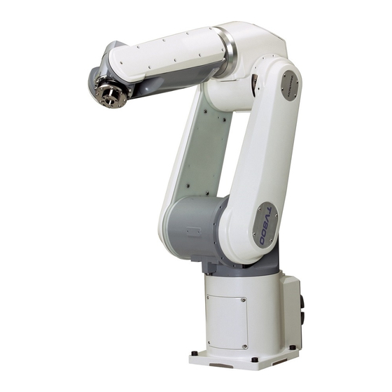
CLEAN TYPE INDUSTRIAL ROBOT SPECIFICATIONS MANUAL Specifications Name of Each Part Fig. 1.1 shows the name of each part of the robot. Axis 3 Axis 4 Arm 2 (1) (rotation) (rotation) Arm 2 (2) Axis 2 (rotation) Arm 1 duct Arm 3 Arm 1 Axis 5... -
Page 9: External Dimensions
CLEAN TYPE INDUSTRIAL ROBOT SPECIFICATIONS MANUAL External Dimensions The robot external dimensions are shown in Fig. 1.2.and in Fig. 1.3, and the operating range is shown in Fig. 1.4.and in Fig. 1.5. Connector panel for hand Dimensions used for cable connections Fig. - Page 10 CLEAN TYPE INDUSTRIAL ROBOT SPECIFICATIONS MANUAL Connector panel for hand Dimensions used for cable connections Fig. 1.3 External dimensions of the TV1000 STE 80768 – 9 –...
- Page 11 CLEAN TYPE INDUSTRIAL ROBOT SPECIFICATIONS MANUAL Point P: J6 intersection point operating Tool flange surface Point P operating Point P Operating range of tool flange surface and J6 intersection point Fig. 1.4 TV800 operating range STE 80768 – 10 –...
- Page 12 CLEAN TYPE INDUSTRIAL ROBOT SPECIFICATIONS MANUAL Point P: J6 intersection point operating Tool flange surface Point P operating Point P Connector panel for hand Tool flange surface Point P operating Fig. 1.5 TV1000 operating range STE 80768 – 11 –...
-
Page 13: Specifications Table
CLEAN TYPE INDUSTRIAL ROBOT SPECIFICATIONS MANUAL Specifications Table Item Specifications Structure Vertical multi-joint 6-axis robot Model TV800-CR TV800-CR-BL TV1000-CR TV1000-CR-BL Applicable controller TS3100 *1 Mass of actuator 45.5kg 47kg No. of controlled axes Arm length 800mm (380mm + 420mm) 1000mm (480mm + 520mm) -
Page 14: Delivery
CLEAN TYPE INDUSTRIAL ROBOT SPECIFICATIONS MANUAL Delivery Unpacking and Transport Based on the customer’s request, the robot and controller are shipped in clean packaging (equivalent to ISO class 5), wooden crate packaging, or cardboard packaging. Open the packaging at a location suitable for future transport and installation, and be careful at all times that you do not damage the robot or controller. - Page 15 CLEAN TYPE INDUSTRIAL ROBOT SPECIFICATIONS MANUAL The packaging is opened using the procedure below. • Use a lifter or other device to transport the package to the entry room of the clean room in the state shown in Fig. 2.1 •...
-
Page 16: Weight And External Dimensions
CLEAN TYPE INDUSTRIAL ROBOT SPECIFICATIONS MANUAL Weight and External Dimensions The robot weight and external dimensions during transport are shown in Fig. 2.3. Securing Suspension jigs Joint Angle (deg.) Joint Angle (deg.) Robot body weight (including shipping jigs) 47 kg (48.5kg) Fig. -
Page 17: Robot Transport Notes
CLEAN TYPE INDUSTRIAL ROBOT SPECIFICATIONS MANUAL Robot Transport Notes Important points during transport are provided below. Additional points not provided below are identical to the standard machine. Refer to the separate “TV800/TV1000 Instruction Manual: Installation and Transport”. Wire Fig. 2.4 Lifting up the robot CAUTION •... - Page 18 CLEAN TYPE INDUSTRIAL ROBOT SPECIFICATIONS MANUAL DO NOT hold the arms 2 and 3. Handling areas Handling areas Fig. 2.5 Robot handling areas After the installation, remove the clamp and eyebolt used for transport. CAUTION • When lifting up the robot by workers, hold the locations (arrowed parts) by hands as shown in Fig.
-
Page 19: Installation
0.98m/s or less Dust No inductive dust should exist. Consult with Toshiba Machine first if you wish to use the robot and controller in a dusty environment. No corrosive or combustible gas should exist. Sunlight The robot and controller should not be exposed to direct sunlight. -
Page 20: Suction Rate
CLEAN TYPE INDUSTRIAL ROBOT SPECIFICATIONS MANUAL Suction Rate A specified rate of suction air is supplied from the suction one-touch joint on the connector cover (base rear section) for enabling a cleanness of ISO class 3. The suction device and suction air tubes (6mm diameter) must be obtained by the customer. -
Page 21: Coordinate System
CLEAN TYPE INDUSTRIAL ROBOT SPECIFICATIONS MANUAL Coordinate System The robot's joint angle origin (0° position) is factory-calibrated according to the base reference planes. Fig. 3.1 shows the base coordinate system and origin of each axis joint angle. Axis 6 Axis 4 Axis 1 Axis 5 Axis 3... -
Page 22: Installing The Robot
CLEAN TYPE INDUSTRIAL ROBOT SPECIFICATIONS MANUAL Installing the Robot The robot is secured, using the set holes on the base (four (4) places). Use M10 hexagon socket head cap screws (made of stainless steel). The robot installation method is shown in Fig. 3.4. Reference planes are provided on the base unit. -
Page 23: Tool Interface
CLEAN TYPE INDUSTRIAL ROBOT SPECIFICATIONS MANUAL Tool Interface Tool mounting and tool signals are identical to the standard machine. Refer to the separate “TV800 Instruction Manual: Installation and Transport”. Tool Air Tubes Two lines are provided for tool air tubes. The outer diameter of the air tubes is 6mm. These tubes are shown in Fig. -
Page 24: Maintenance
CLEAN TYPE INDUSTRIAL ROBOT SPECIFICATIONS MANUAL Maintenance Maintenance Items The inspection items for the clean specifications are shown below. Inspection Location of Daily 2-year Inspection item inspection inspection inspection Visual inspection for cracks and Each other defects in packing Replacement Each cover ○... -
Page 25: Mounting And Removing The Covers
CLEAN TYPE INDUSTRIAL ROBOT SPECIFICATIONS MANUAL Mounting and Removing the Covers Rubber packing is fitted onto the cover mounting surfaces of the clean type industrial robot. Be sure to carefully follow the procedures in this section when mounting and removing the covers. DANGER •... -
Page 26: Base Covers
CLEAN TYPE INDUSTRIAL ROBOT SPECIFICATIONS MANUAL 5.2.1 Base Covers There are two covers for the base section: the base cover and connector panel. Each cover is mounted and removed using the same procedure as the standard machine. Each cover is secured to the base by four bolts with a rubber packing inserted in between. -
Page 27: Base Swivel Cover
CLEAN TYPE INDUSTRIAL ROBOT SPECIFICATIONS MANUAL 5.2.2 Base Swivel Cover The base swivel cover is secured to the base swivel unit by six Phillips truss head screws (M4x8) with a rubber packing inserted in between. When mounting the cover, be careful that no cables get pinched in between. Base swivel cover Packing * The internal cables are... -
Page 28: Arm 1 Cover
CLEAN TYPE INDUSTRIAL ROBOT SPECIFICATIONS MANUAL 5.2.3 Arm 1 Cover The arm 1 cover is secured to the hexagonal supports attached to the arm 1 duct plate by Phillips truss head screws (M4x8). When mounting the cover, fit the cover into the groove along the duct plate side. Be careful that the packing for the cover does not come off. -
Page 29: Arm 2 Cover (1)
CLEAN TYPE INDUSTRIAL ROBOT SPECIFICATIONS MANUAL 5.2.4 Arm 2 Cover (1) The arm 2 cover (1) is secured to arm 2 by six Phillips truss head screws (M4x8) with a rubber packing inserted in between. When mounting the cover, be careful that no cables get pinched in between. Arm 2 cover (1) Packing * The internal cables are... -
Page 30: Arm 2 Cover (2)
CLEAN TYPE INDUSTRIAL ROBOT SPECIFICATIONS MANUAL 5.2.5 Arm 2 Cover (2) The arm 2 cover (2) is secured to arm 2 by 9 Phillips truss head screws on each side for a total of 18 screws (M3x12 and M3x8) with a rubber packing inserted in between. When mounting the cover, be careful that no cables get pinched in between. -
Page 31: Arm 3 Cover
CLEAN TYPE INDUSTRIAL ROBOT SPECIFICATIONS MANUAL 5.2.6 Arm 3 Cover The arm 3 cover is secured to arm 3 by four hexagon socket head cap screws (M3 x 35) with a rubber packing inserted in between. When mounting the cover, be careful that no cables get pinched in between. Packing Arm 3 cover * The internal cables are... -
Page 32: Replacement Parts For Maintenance
The other replacement parts for maintenance are identical to the TV800/TV1000 standard machine. For further information, refer to the “TV800/TV1000 Instruction Manual: Maintenance”. To purchase the replacement parts for maintenance, be sure to first check the robot body serial number before contacting Toshiba Machine. STE 80768 – 31 –... - Page 33 CLEAN TYPE INDUSTRIAL ROBOT SPECIFICATIONS MANUAL APPROVED BY: CHECKED BY: PREPARED BY: STE 80768 – z –...
Need help?
Do you have a question about the TV800-CR and is the answer not in the manual?
Questions and answers