Table of Contents
Advertisement
Quick Links
Advertisement
Table of Contents

Subscribe to Our Youtube Channel
Related Manuals for Advantech WISE-750


Summary of Contents for Advantech WISE-750
- Page 1 User Manual WISE-750 Intelligent Vibration Sensing Gateway...
- Page 2 No part of this manual may be reproduced, copied, translated, or transmitted in any form or by any means without the prior written permission of Advantech Co., Ltd. The information provided in this manual is intended to be accurate and reliable.
- Page 3 This product has passed the CE test for environmental specifications when shielded cables are used for external wiring. We recommend the use of shielded cables. This type of cable is available from Advantech. Please contact your local supplier for ordering information.
- Page 4 WISE-750 User Manual...
-
Page 5: Table Of Contents
Figure 4.3 Feature Extraction Page........... 19 Figure 4.4 Machine Learning Page..........20 Figure 4.5 Run Page..............20 Figure 4.6 Multiple WISE-750 being listed in device tree view .. 21 IP Configuration ..................21 Overview of WISE-750 Operation ............21 Figure 4.7 Process of the WISE-750 application ....... 21 Data Acquisition Parameters.............. - Page 6 Dynamic Performance ..............30 Triggers....................31 Isolated Digital Input ................31 Isolated Digital Output................31 General ....................31 Appendix B Algorithms ......... 33 Appendix C I/O Ranges ......... 35 Modbus Mapping ..................36 Table C.1: Modbus Mapping............36 WISE-750 User Manual...
-
Page 7: Chapter 1 Introduction
Chapter Introduction This chapter introduces WISE-750 and its typical applications. Sections include: Features Applications Installation Guide Software Overview Accessories... -
Page 8: Features
WISE-750 is a direct solution, straight onto the PHM for rotational machinery, i.e. motor actuated machinery such as machine tools, pumps and elevators etc. It mea- sures the vibration through the accelerometer PCL-M10 packed along with the WISE-750. After the measurement, it processes and gets the results then, gives the machine health status. -
Page 9: Accessories
Figure 1.1 Installation Flow Chart Accessories Advantech offers a complete set of accessory products to support the WISE-750 module. These accessories include: Sensor PCL-M10-3E Industrial Accelerometer PSD-A40W24 DIN Rail AC to DC 100-240V 40W 24V PSD-A40W12 DIN Rail AC to DC 100-240V 40W 12V ... - Page 10 WISE-750 User Manual...
-
Page 11: Chapter 2 Installation
Chapter Installation... -
Page 12: Unpacking
Configuration with WISE-750 Utility To start using the WISE-750, you need to download and install the utility first. The util- ity can be downloaded from Advantech support portal (https://support.advant- ech.com/support/new_default.aspx). After the installation, you can find the program under Start/Advantech Automation/WISE750/WISE-750 Utility. - Page 13 The WISE-750 should be listed in the left column with the IP address labeled. If you don't see the module be listed, you may check: a. The Ethernet cable connection b. Firewall are shut down on both Windows and your anti-virus c.
- Page 14 WISE-750 User Manual...
-
Page 15: Chapter 3 Hardware Overview And Signal
Hardware Overview and Signal Connections This chapter provides useful information about how to connect input and output signals to the WISE-750 Module via the I/O con- nector. Sections include: Overview IO Indicators and Pin Definition Signal Connections... -
Page 16: Overview
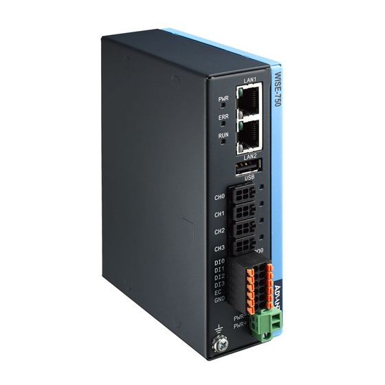
PC and other hardware devices. This chapter provides useful information about how to connect input and output signals to the WISE-750 module via the I/O connector. Hardware Overview Please refer to Figure 3.1 for the location of all IO connectors and indicators. -
Page 17: Io Status Indicators
Program Not Ready Program Ready program - Updating firmware Channel Status Each of the analog input channel has a corresponded LED indicator. The LED lights up when the channel alarm happens. LED Status Channel OK Channel Alarm WISE-750 User Manual... -
Page 18: Signal Connection
The WISE-750-02A1E package includes 2 accelerometers PCL-M10-3E by default. The sensor can be connected to the WISE-750 analog channel 0~3 directly. How- ever, if you'd like to connect your own sensor to the WISE-750, you should connect your sensor to the 4-pin connector with the pin-assignment below. -
Page 19: Isolated Digital Input
Figure 3.5 WISE-750 connect to PCL-M10 3.3.3 Isolated Digital Input Each of the isolated digital input channels accepts bi-directional 10 ~ 30 VDC voltage inputs. This means that both positive and negative voltage can be applied to an iso- lated input pin (VIN). Figure 2 shows how to connect an external input source to one of the module's isolated input channels. -
Page 20: Isolated Digital Output
Install the DIN-rail kit using the 3 screws provided in the pack. Field Wiring Considerations When you use WISE-750 module to acquire data from outside, noises in the environ- ment might significantly affect the accuracy of your measurements if due cautions are not taken. -
Page 21: Ethernet Connection
Ethernet Connection The WISE-750 has two LAN port with RJ45 connector. To connected with WISE-750, you should use at least CAT 5e cable with RJ-45 connector to connect to the WISE- 750. The WISE-750 supports daisy chain. The topology could be expanded with this fea- ture. - Page 22 WISE-750 User Manual...
-
Page 23: Chapter 4 Device Configuration
Chapter Device Configuration Sections include: Software Interfaces IP Configuration Overview of WISE-750 Opera- tion Data Acquisition Parameters Trigger Settings Operation Modes... -
Page 24: Software Interfaces
Software Interface There are two parts in WISE-750 utility. One is the device tree view on the left hand side, the other is specific settings. The device will be listed on the device tree view, labeled with its IP address when the system is connected with WISE-750 via Ether- net. - Page 25 Device Test This function allows you to tests all the functions of WISE-750 in terms of signal con- nection. Each page performs its corresponded functions from analog input, digital input to digital output. Note that the FFT plot in analog test is transformed from time- domain data in the computer.
- Page 26 The software supports multiple connection in the system, no matter if it's connected by daisy chain, through switch etc. The devices would be listed in the system when they are set to different IPs and connected. (Figure 4.6) WISE-750 User Manual...
-
Page 27: Ip Configuration
The device itself has a default IP setting of 10.0.0.1. In order to successfully connect to WISE-750 in the beginning of using the device, you need to configure your NIC IP connected to WISE-750 to the same section (10.0.0.x with sub-net mask 255.255.255.0). -
Page 28: Data Acquisition Parameters
If the section count is set to 0, this would act as continuous mode. Each cycle would be started right after previous cycle until stop trigger happens. In this mode, the trig- ger would act as a gate to control the iteration. See Figure 4.9. Figure 4.9 Trigger and Cycle Count WISE-750 User Manual... -
Page 29: Trigger Settings
Input, and Analog Input from the respective channels to be chosen from. Whenever the trigger is set to None, WISE-750 will run right after the setting is downloaded to the machine. Otherwise, the cycles would start when receiving the trigger signal/ action. -
Page 30: Trigger Level
This would only be available when using analog triggers. This is the trigger voltage level. The trigger would be generated when the voltage passes through this value. This field would only be available when the trigger source is analog input. WISE-750 User Manual... -
Page 31: Operation Modes
Operation Modes There are three modes that could be run in the WISE-750. They are Datalogger, Fea- ture Extraction, and Intelligent Mode respectively. You can set them in the WISE-750 Utility. They are independent modes. They each have their own functions respec- tively. -
Page 32: Feature Extraction Mode
Alarm Threshold Setting The training session will build and download the model to the WISE-750. In the infer- ence session, the WISE-750 will indicates if the iteration is OK or NG. The WISE-750 will give a score to indicate the status of the measured machine/component. The score is calculated using success rate in the past N iterations, while N is user-config- urable in Alarm Setting page. -
Page 33: Device Communication
For example, if WISE-750 finds that channel 0 fail to pass the threshold, the digital output 0 will be set to High level. Otherwise, in the normal situation, the digital output will stay in Low level. - Page 34 WISE-750 User Manual...
-
Page 35: Appendix A Specifications
Appendix Specifications... -
Page 36: Analog Input
Effective number of bits (ENOB): 13.5 Bits @(fin = 1KHz) Signal-to-Noise Ration (SNR): 85 dB @(fin = 1KHz) Total Harmonic Distortion (THD): -91 dB @(fin = 1KHz) Total Harmonic Distortion pulse Noise (THD+N): -84 dB @(fin = 1KHz) WISE-750 User Manual... -
Page 37: Triggers
Operating temperature: 0 to 60 °C (32 to 140 °F) Storage temperature: -40 to 70 °C (-40 to 158 °F) Operating humidity: 10 to 90% RH, non-condensing Storage humidity: 5 to 95% RH, non-condensing WISE-750 User Manual... - Page 38 WISE-750 User Manual...
-
Page 39: Appendix B Algorithms
Appendix Algorithms... - Page 40 (voltage)/(sensitivity). PCL-M10 itself will have a DC voltage of 5V in default. So, the formula to transfer PCL-M10 voltage to vibration is Acceleration =(Voltage - 5 / 0.08) g For example, a 6V in measurement could be transferred to (6-5)/0.08 = 12.5g. WISE-750 User Manual...
-
Page 41: Appendix C I/O Ranges
Appendix I/O Ranges... -
Page 42: Modbus Mapping
40401 0: Stop, 1: Start *The value includes 2-digit decimal. To retrieve the actual value, a division of 100 should be performed. For example, if the value read back is 1000, the actual value would be 1000/100 = 10. WISE-750 User Manual... - Page 43 WISE-750 User Manual...
- Page 44 No part of this publication may be reproduced in any form or by any means, such as electronically, by photocopying, recording, or otherwise, without prior written permission from the publisher. All brand and product names are trademarks or registered trademarks of their respective companies. © Advantech Co., Ltd. 2021...
Need help?
Do you have a question about the WISE-750 and is the answer not in the manual?
Questions and answers