
Related Manuals for Taylor-Dunn BG-015-00


Summary of Contents for Taylor-Dunn BG-015-00
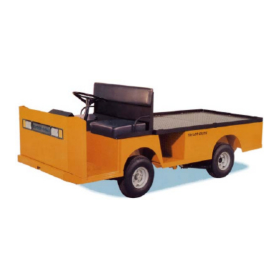
- Page 1 Models Inlcuded: BG-015-00 (G 1-50) T h e B e s t W a y T o G o A b o u t Y o u r B u s i n e s s MANUAL MG-150-03 Operation, Troubleshooting and...
- Page 3 Address inquiries to Reference Permissions, Taylor-Dunn Mfg., 2114 W. Ball Road, Anaheim, CA 92804 ® TAYLOR-DUNN SERVICE CENTER For more information about this and other Taylor-Dunn manuals, please write Taylor-Dunn ® ® Taylor-Dunn Mfg.
- Page 4 B2-10 Ambulance B2-48 With Dump Bed Option B2-48 with Steel Cab, Foldaway 4-Passenger Seat and Stake Sides ET 3000 P2-50 30,000 Pound Tow Tractor ET1-50 Full Size Truck...
-
Page 5: Table Of Contents
Table of Contents Contents Introduction Front Axle Service About this manual ........2 Inspect the Front Wheel Bearings and Who Should Read This Manual ....3 King Pin ..........2 Responsibilities ........3 Adjust Front Wheel Bearings ....3 How To Use This Manual ......4 Front Axle Removal and Installation .. - Page 6 Table of Contents Replace the Master Cylinder ....24 APPENDIX A-Special Tools Repair the Master Cylinder ....... 26 Appendix B: Standard Hardware Suspension Suggested Torque Limits Replace the Rear Springs ......2 Hardware Identification ......2 Replace the Front Springs ....... 3 Standard Head Markings ........
- Page 7 Introduction Contents About this manual ......... 2 Who Should Read This Manual ....3 Responsibilities ..........3 How To Use This Manual ......4 Conventions ............. 5 How to Identify Your Vehicle ......6 Taking Delivery of Your Vehicle ....7...
-
Page 8: Introduction
Please continue to read this manual and enjoy this high quality Taylor-Dunn ® vehicle. This manual is to serve as a guide for the service, repair, and operation of Taylor-Dunn ® vehicles and is not intended as a training guide. Taylor-Dunn ®... -
Page 9: Who Should Read This Manual
Of the Service Personnel... The service personnel are responsible for the service and maintenance of the vehicle. At no time should a service person allow any untrained personnel to service or repair this or any Taylor-Dunn ® vehicle. For the purposes of training, a qualified service person may oversee the repairs or services being made to a vehicle by an individual in training. -
Page 10: How To Use This Manual
INTRODUCTION HOW TO USE THIS MANUAL This manual is organized into five main sections: INTRODUCTION This section describes how to use this service manual and how to identify your vehicle. Safety Rules and Operating Instructions This section outlines the safety and operational issues, location and operation of controls, and the operational checks that are to be performed on this vehicle. -
Page 11: Conventions
INTRODUCTION Conventions Symbols and/or words that are used to define warnings, cautions, instructions, or notes found throughout this manual: A shaded box with the word “Warning” on its left denotes a warning. A warning alerts the reader of a hazard that may result in injury to themselves or others. -
Page 12: How To Identify Your Vehicle
INTRODUCTION HOW TO IDENTIFY YOUR VEHICLE This manual applies to vehicles with the same model and serial numbers listed on the front cover. These vehicles are designed for driving on smooth surfaces in and around facilities such as industrial plants, nurseries, institutions, motels, mobile home parks, and resorts. They are not to be driven on public highways. -
Page 13: Taking Delivery Of Your Vehicle
® distributor and report the problem. The report must be made within 24 hours of receiving the vehicle and its accessories. The only personnel authorized to repair, modify, or adjust any part of this or any Taylor-Dunn ® vehicle is a factory authorized service technician. - Page 14 SC1-59 Stock Chaser B2-48 With Stake Side Dump Bed Option E4-55 Sit Down Tow Tractor C4-25 Sit Down Tow Tractor...
- Page 15 Safety Rules and Operating Instructions TABLE OF CONTENTS Standard Specifications Burden Carrier Vehicle Operational Guidelines ....8 (chassis ONLY*) ........2 Safety Guidelines ............ 8 Starting: ..............8 Safety Rules and Guidelines ......3 While driving: ............9 Driver Training Program ....... 4 Loading and Unloading ..........
-
Page 16: Safety Rules And Operating Instructions
SAFETY RULES AND OPERATING INSTRUCTIONS STANDARD SPECIFICATIONS BURDEN CARRIER (CHASSIS ONLY*) ITEM MODEL SPECIFICATION Occupancy 1-driver, 1-passenger Dimensions 304.8 L x 112.4W x 122H Centimeters 120L x 44.25W x 48H Inches Turning Radius 317.5 Centimeters (125 Inches) Dry Weight 517 kg (1140 lbs) Maximum Load 681kg (1,500 lbs) Deck dimensions... -
Page 17: Safety Rules And Guidelines
SAFETY RULES AND OPERATING INSTRUCTIONS SAFETY RULES AND GUIDELINES It is the responsibility of the owner of this vehicle to assure that the operator understands the various controls and operating characteristics of this vehicle (extracted from the American National Standards Institute Personnel and Burden Carriers ANSI B56.8). -
Page 18: Driver Training Program
SAFETY RULES AND OPERATING INSTRUCTIONS DRIVER TRAINING PROGRAM According to ANSI B56.8, the owner of this vehicle shall conduct an Operator Training program for all those who will be operating this vehicle. The training program shall not be condensed for those claiming to have previous vehicle operation experience. -
Page 19: Vehicle Controls
SAFETY RULES AND OPERATING INSTRUCTIONS VEHICLE CONTROLS Ignition Switch An ignition switch, located on the right center side of the instrument Starting panel, starts the engine. Refer to in this section for instructions for this switch. The ignition switch should be in the “OFF” position whenever the operator leaves the vehicle. -
Page 20: Fuel Gauge
SAFETY RULES AND OPERATING INSTRUCTIONS Fuel Gauge The fuel gauge is located to the left of the hour meter. The needle pointing to “F” indicates a full tank of fuel, “E” indicates an empty tank of fuel. Hour Meter The hour meter is located to the right of the battery status indicator. It records the number of hours the vehicle has been in operation. -
Page 21: Seat Interlock Switch
SAFETY RULES AND OPERATING INSTRUCTIONS Accelerator Pedal The accelerator pedal is located to the right of the brake pedal. It controls the speed of the vehicle and operates similar to the accelerator pedal in an automobile. Depress the pedal to increase speed and release the pedal to decrease speed. -
Page 22: Vehicle Operational Guidelines
SAFETY RULES AND OPERATING INSTRUCTIONS VEHICLE OPERATIONAL GUIDELINES Safety Guidelines • Only qualified and trained operators may drive this vehicle. • Drive only on level surfaces or on surfaces having an incline of no more than 10% (5.6 degrees). • Drive slowly when making a turn, especially if the ground is wet or when driving on an incline. -
Page 23: While Driving
SAFETY RULES AND OPERATING INSTRUCTIONS While driving: • Slow down and sound the horn to warn pedestrians or when approaching a corner or other intersection. • No reckless driving. • Do not drive this vehicle on steep inclines or where prohibited. •... -
Page 24: Returning To Service
SAFETY RULES AND OPERATING INSTRUCTIONS STORING AND RETURNING TO SERVICE Both storing your vehicle and returning it to service should only be performed by authorized personnel. Storing Your Vehicle • Clean the battery, then fill and charge before putting the vehicle in storage. Do not store batteries in a discharged condition. -
Page 25: Periodic Maintenance Checklist (Chassis Only*)
SAFETY RULES AND OPERATING INSTRUCTIONS PERIODIC MAINTENANCE CHECKLIST (CHASSIS ONLY*) Semi - Weekly Monthly Quaterly Annualy Maintenance Item Annual (20hrs) (80hrs) (250hrs) (1000hrs) (500hrs) Check Condition of Tires and Tire Pressure Check All Lights, Horns, Beepers and Warning Devises Check and Fill Battery Check Brake System Check Steering System Check for Fluid Leaks... -
Page 26: Maintenance Guidelines For Severe Duty Applications
SAFETY RULES AND OPERATING INSTRUCTIONS MAINTENANCE GUIDELINES FOR SEVERE DUTY APPLICATIONS This maintenance checklist is based on the average application. If the vehicle is operated under “severe conditions”, Service procedures should be conducted more frequently than specified. The frequency of service under severe conditions is determined by the use of the vehicle. -
Page 27: General Maintenance
General Maintenance TABLE OF CONTENTS Maintenance Guidelines ....... 2 Maintenance Guidelines for Vehicles Used in Severe Conditions ..... 3 Troubleshooting Guide ......... 4 Lubrication Chart .......... 5... -
Page 28: Maintenance Guidelines
• Inspect and maintain battery limit switches, protective devices, electrical conductors, and connections in conformance with Taylor-Dunn’s ® recommended procedures. • Keep the vehicle in clean condition to minimize fire hazards and facilitate detection of loose or defective parts. -
Page 29: Troubleshooting Guide
Maintenance, Service and Repair TROUBLESHOOTING GUIDE Symptom Probable Cause Front End Out of Alignment Steering Pulls in One Direction Low Tire Pressure Dry Lube Points in Steering Linkage Hard Steering Damaged King Pin/Ball Joint Low Tire Pressure Worn Ball Joints Excessive Steering Play Mis-Adjusted or Worn Steering Gear Loose Steering Linkage... -
Page 30: Lubrication Chart
Maintenance, Service and Repair LUBRICATION CHART 7, 9 Transmission #7 and #9 as viewed from left rear Description Locations Lubricant Type Front Leaf Springs General Purpose Grease King Pin General Purpose Grease Ball Joints General Purpose Grease Front Wheel Bearings High Temperature Wheel Bearing Grease Transmission Drain Plug Transmission Fill Plug... -
Page 31: Engine / Transmission
Engine / Transmission For information regarding Rear Axle service, refer to supplementary manual part number M7-001-07 For information regarding Kohler Command Engine service, refer to the Kohler web site at: www.kohlerengines.com Enter TP-2428 in the search box. Refer to the specifications page in this manual for the Kohler Engine model and spec number. -
Page 33: Shiftlinkage
Shift Linkage Contents Adjustment ............ 2... -
Page 34: Adjustement
Maintenance, Service, and Repair ADJUSTMENT Do not modify the stainless steel shift cable mounting plate at the transmission. This mounting plate is spring steel and functions as an active part of the shifting mechanism. Modification of this mounting plate may cause improper operation of the shift linkage resulting in damage to the transmission. -
Page 35: Front Axle Service
Front Axle Service TABLE OF CONTENTS Inspect the Front Wheel Bearings and King Pin ........... 2 Adjust Front Wheel Bearings ....... 3 Front Axle Removal and Installation .... 4 Removal ..............4 Installation ..............5 Front Axle Disassembly ........ 6 Replace Front Wheel Bearings ..... -
Page 36: Inspect The Front Wheel Bearings And King Pin
Maintenance, Service, and Repair INSPECT THE FRONT WHEEL BEARINGS AND KING PIN 1. Make sure the key-switch is in the “OFF” position, then remove the key. 2. Place the Shift lever in the neutral position. 3. Set the park brake. 4. -
Page 37: Adjust Front Wheel Bearings
Maintenance, Service, and Repair ADJUST FRONT WHEEL BEARINGS 1. Make sure the key-switch is in the “OFF” position, then remove the key. 2. Place the Shift lever in the neutral position. 3. Set the park brake. 4. Place blocks under the rear wheels to prevent vehicle movement. 5. -
Page 38: Front Axle Removal And Installation
Maintenance, Service, and Repair FRONT AXLE REMOVAL AND INSTALLATION Removal 1. Make sure the key-switch is in the “OFF” position, then remove the key. 2. Place the Shift lever in the neutral position. 3. Set the park brake. 4. Place blocks under the rear wheels to prevent vehicle movement. 5. -
Page 39: Installation
Maintenance, Service, and Repair Installation 1. Make sure the key-switch is in the “OFF” position, then remove the key. 2. Place the Shift lever in the neutral position. 3. Set the park brake. 4. Place blocks under the rear wheels to prevent vehicle movement. 5. -
Page 40: Front Axle Disassembly
Maintenance, Service, and Repair FRONT AXLE DISASSEMBLY Disassembling and reassembling involves removing and replacing the left and right steering knuckles and king pin bushings. Refer to the following sections for information regarding these procedures: Replace the Steering Knuckle Replace the King Pins and Bushings NOTE: The front axle does not have to be removed unless the axle beam Front Axle Removal and must be replaced. -
Page 41: Replace Front Wheel Bearings
Maintenance, Service, and Repair REPLACE FRONT WHEEL BEARINGS 1. Make sure the key-switch is in the “OFF” position, then remove the key. 2. Place the Shift lever in the neutral position. 3. Set the park brake. 4. Place blocks under the rear wheels to prevent vehicle movement. 5. - Page 42 Maintenance, Service, and Repair 13. Install the hub dust cap. 14. Reinstall the brake body and the tire/wheel assembly. Brakes NOTE: Refer to the section for information regarding the installation of the brake body. 15. Lower the vehicle. 16. Reconnect the main positive and negative cables at the batteries. 17.
-
Page 43: Replace The King Pins And Bushings
Maintenance, Service, and Repair REPLACE THE KING PINS AND BUSHINGS There are different types of king pin bushings depending on the configuration of your vehicle. • Bronze bushings in the axle beam. • Bronze bushings in the steering knuckle. • Metal backed teflon bushings in the axle beam or suspension arm. - Page 44 Maintenance, Service, and Repair Replace the Steering Knuckle 7. Remove the steering knuckle. Refer to for information regarding removing the steering knuckle. NOTE: It is not necessary to remove the tie rod or drag link for this procedure. 8. Press the king pin bushings out from the axle, steering knuckle or suspension arm. 9.
-
Page 45: Replace The Steering Knuckle
Maintenance, Service, and Repair REPLACE THE STEERING KNUCKLE 1. Make sure the key-switch is in the “OFF” position, then remove the key. 2. Place the Shift lever in the neutral position. 3. Set the park brake. 4. Place blocks under the rear wheels to prevent vehicle movement. 5. - Page 46 Maintenance, Service, and Repair 12. Thoroughly clean and/or replace all bearings, nuts, washers, and bushings. NOTE: Both the left and right side bushings and thrust bearings should be replaced as a set. 13. Assemble in reverse order. 14. Pack the thrust bearing with grease. 15.
-
Page 47: Steering Component Service
Steering Component Service TABLE OF CONTENTS Front End Alignment ........2 Inspect Ball Joints ......... 6 Inspect Rod Ends .......... 7 Adjust the Steering Gear ....... 8 Replace the Steering Shaft ......10 Replace the Steering Wheel ......12 Replace the Steering Gear ......13 Replace the Steering Gear ...... -
Page 48: Front End Alignment
Maintenance, Service, and Repair FRONT END ALIGNMENT This section will refer to two different types of ball joints. One type is has a grease fitting and a tapered shaft where it is fitted to the steering arm or pitman arm. The second type cannot be greased and has a straight shaft. - Page 49 Maintenance, Service, and Repair 10. At this point both the steering wheel and the front wheels should be tied up and held in position. If one or the other is not tied up then you must start from the beginning. Do not drive the vehicle while the steering wheel or front wheels are tied in position.
- Page 50 Maintenance, Service, and Repair Front wheel alignment NOTE: It is recommended to center the steering before aligning the front Center the Steering wheels. Refer to the section for information. 1. Make sure the key-switch is in the “OFF” position, then remove the key.
- Page 51 Maintenance, Service, and Repair 11. Measure the distance between the lines at the front Front Measurement of the tires. 12. Measure the distance between the lines at the rear of the tires. Sleeve Clamps 13. Adjust the tie rod so that the distance at the front and rear of the tires is the same.
-
Page 52: Inspect Ball Joints
Maintenance, Service, and Repair INSPECT BALL JOINTS NOTE: A set of ball joints and/or rod ends will wear at the same rate. If a ball joint and or rod end is worn out, then all should be replaced as a set. 1. -
Page 53: Inspect Rod Ends
Maintenance, Service, and Repair INSPECT ROD ENDS NOTE: A set of ball joints and/or rod ends will wear at the same rate. If a ball joint and or rod end is worn out, then all should be replaced as a set. 1. -
Page 54: Adjust The Steering Gear
Maintenance, Service, and Repair ADJUST THE STEERING GEAR NOTE: In some vehicle configurations it may be necessary to remove the Replace the steering gear to perform this procedure. Refer to Steering Gear for information regarding removing the steering gear. 1. Make sure the key-switch is in the “OFF” position, then remove the key. - Page 55 Maintenance, Service, and Repair 13. While rotating the input shaft back and forth through its centered position, adjust the gear lash adjusting screw so that there is a slight drag as the steering gear is rotated through its centered position. 14.
-
Page 56: Replace The Steering Shaft
Maintenance, Service, and Repair REPLACE THE STEERING SHAFT 1. Make sure the key-switch is in the “OFF” position, then remove the key. 2. Place the Shift lever in the neutral position. 3. Set the park brake. 4. Place blocks under the rear wheels to prevent vehicle movement. 5. - Page 57 Maintenance, Service, and Repair 11. Remove the steering shaft from the vehicle. 12. Lightly grease the input shaft splines, steering wheel splines and the upper steering shaft bushing. 13. Install the steering shaft in reverse order using a new pinch bolt. Orientate the shaft so that the pinch bolt is opposite the flat in the steering gear shaft.
-
Page 58: Replace The Steering Wheel
Maintenance, Service, and Repair REPLACE THE STEERING WHEEL 1. Make sure the key-switch is in the “OFF” position, then remove the key. 2. Place the Shift lever in the neutral position. 3. Set the park brake. 4. Place blocks under the rear wheels to prevent vehicle movement. 5. -
Page 59: Replace The Steering Gear
Maintenance, Service, and Repair REPLACE THE STEERING GEAR 1. Make sure the key-switch is in the “OFF” position, then remove the key. 2. Place the Shift lever in the neutral position. 3. Set the park brake. 4. Place blocks under the rear wheels to prevent vehicle movement. 5. - Page 60 Maintenance, Service, and Repair REPLACE THE STEERING GEAR 1. Make sure the key-switch is in the “OFF” position, then remove the key. 2. Place the Shift lever in the neutral position. 3. Set the park brake. 4. Place blocks under the rear wheels to prevent vehicle movement. 5.
-
Page 61: Replace The Ball Joints, Tie Rods, And Drag Link
Maintenance, Service, and Repair REPLACE THE BALL JOINTS, TIE RODS, AND DRAG LINK This section will refer to two different types of ball joints. One type is has a grease fitting and a tapered shaft where it is installed on the steering arm or pitman arm. The second Rod End cannot be greased and has a straight shaft. - Page 62 Maintenance, Service, and Repair 10. Install the new rod end into the steering sleeve. Screw it into the sleeve the same number of turns counted in the previous step. Do not tighten the rod end clamp or jam nut at this time. 11.
-
Page 63: Replacing The Drag Link
Maintenance, Service, and Repair 12. Install the ball joint into the steering arm. Tighten the ball joint nut to 40-45 ft-lbs. and install a new cotter pin. 13. Realign the front wheels. Steering NOTE: Refer to the section for information regarding realignment of the front wheels. -
Page 64: Replacing The Tie Rod
Maintenance, Service, and Repair 11. Lower the vehicle. 12. Reconnect the main positive and negative cables at the batteries. 13. Remove the blocks from behind the wheels. 14. Release the park brake and test drive the vehicle. Replacing the Tie Rod The Tie Rod is the linkage that connects the two steering knuckles together. -
Page 65: Center The Steering Gear
Maintenance, Service, and Repair CENTER THE STEERING GEAR NOTE: The drag link must be disconnected from the pitman arm or the pitman arm removed from the steering gear to perform this procedure. Refer to the appropriate section for details. 1. Remove the pitman arm. 2. -
Page 66: Repair The Steering Gear
Maintenance, Service, and Repair REPAIR THE STEERING GEAR Disassembly NOTE: The steering gear must be removed from the vehicle for this procedure. Refer to Replace the Steering Gear section for information regarding removing the steering gear. NOTE: The steering gear is packed with grease. Only perform maintenance on the steering gear in an area that will contain any grease that may spill out of the steering gear when it is disassembled. - Page 67 Maintenance, Service, and Repair 4. Remove the worm shaft and ball nut assembly from the bottom of the housing. 5. Remove the worm shaft seal. 6. Remove the pitman shaft seal. 7. Remove the upper worm bearing and bearing cup from the housing.
- Page 68 Maintenance, Service, and Repair 9. Place the upper worm bearing on the worm shaft and install the worm shaft/ball nut assembly into the housing being careful not to damage the worm shaft seal. 10. Install the assembled worm bearing adjuster into the housing and tighten just enough to remove all play in the worm shaft.
-
Page 69: Exploded View Of Steering Gear
Maintenance, Service, and Repair Exploded View of Steering Gear Steering Page 23... -
Page 71: Brake Service
Brake Service TABLE OF CONTENTS Inspect the Service Brake ......2 Disc Brake Pads ............2 Disc Brake Rotor ............. 3 Brake Shoes ............4 Brake Drum .............. 4 Park Brake .............. 5 Adjust the Service Brakes ......6 Rear Drum Brakes ........... 6 Adjust the Mechanical Brake Linkages .... -
Page 72: Inspect The Service Brake
Maintenance, Service, and Repair INSPECT THE SERVICE BRAKE Disc Brake Pads Current Taylor-Dunn brakes are asbestos free. However, there is the ® possibility that the original brakes were replaced with aftermarket parts containing asbestos. Since this possibility exists, all brake parts should be handled as if they contain asbestos. -
Page 73: Disc Brake Rotor
Maintenance, Service, and Repair Disc Brake Rotor Current Taylor-Dunn brakes are asbestos free. However, there is the ® possibility that the original brakes were replaced with aftermarket parts containing asbestos. Since this possibility exists, all brake parts should be handled as if they contain asbestos. Refer to appendix C for recommended handling precautions. -
Page 74: Brake Shoes
Maintenance, Service, and Repair Brake Shoes Current Taylor-Dunn brakes are asbestos free. However, there is the ® possibility that the original brakes were replaced with aftermarket parts containing asbestos. Since this possibility exists, all brake parts should be handled as if they contain asbestos. Refer to appendix C for recommended handling precautions. -
Page 75: Park Brake
Maintenance, Service, and Repair Park Brake 1. Make sure the key-switch is in the “OFF” position, then remove the key. 2. Place the Shift lever in the neutral position. 3. Set the park brake. 4. Place blocks under the front wheels to prevent vehicle movement. 5. -
Page 76: Adjust The Service Brakes
Maintenance, Service, and Repair ADJUST THE SERVICE BRAKES Rear Drum Brakes The mechanical and hydraulic brake assemblies are identical except for hydraulic fittings. The adjustment procedure is the same for both the mechanical and hydraulic brakes. NOTE: The brake adjustment is inside of the left and right brake. Do not adjust the brake by means of the brake cables as this will cause mis-operation of the brakes. -
Page 77: Adjust The Mechanical Brake Linkages
Maintenance, Service, and Repair 12. Install the tire/wheel assembly. 13. Repeat this procedure for the opposite side brake. 14. Set the park brake. 15. Reconnect the main positive and negative cables at the batteries. 16. Remove blocks from behind the wheels. 17. -
Page 78: Adjust The Parking Brake
Maintenance, Service, and Repair ADJUST THE PARKING BRAKE Park Brake Handle NOTE: The service brake must be properly adjusted before attempting to Adjust the Service Brakes adjust the parking brake. Refer to for information regarding adjusting the service brakes. The parking brake is adjusted by means of the knob on the end of the parking brake handle. -
Page 79: Park Brake Linkage
Maintenance, Service, and Repair Park Brake Linkage NOTE: Do not use this adjustment for routine adjustments to the parking brake. This adjustment should only be performed when any part of the brake system has been repaired or replaced. 1. Make sure the key-switch is in the “OFF” position, then remove the key. -
Page 80: Check Master Cylinder Fluid
Maintenance, Service, and Repair CHECK MASTER CYLINDER FLUID Do not ingest brake fluid or allow contact with skin or eyes. Always wear protective clothing and a face shield when working with or around brake fluid. SKIN CONTACT Flush area immediately with water for several minutes. If a rash or skin irritation develops, get medical attention immediately. -
Page 81: Bleed The Brake System
Maintenance, Service, and Repair BLEED THE BRAKE SYSTEM Do not ingest brake fluid or allow contact with skin or eyes. Always wear protective clothing and a face shield when working with or around brake fluid. SKIN CONTACT Flush area immediately with water for several minutes. If a rash or skin irritation develops, get medical attention immediately. - Page 82 Maintenance, Service, and Repair 7. Add brake fluid from a new sealed container to the master cylinder. Fill to 1/4” from the top of the master cylinder chamber. • Only use DOT 3 brake fluid from a new sealed container. •...
-
Page 83: Flush The Brake System
Maintenance, Service, and Repair FLUSH THE BRAKE SYSTEM 1. Make sure the key-switch is in the “OFF” position, then remove the key. 2. Place the Shift lever in the neutral position. 3. Set the park brake. 4. Place blocks under the front wheels to prevent vehicle movement. 5. -
Page 84: Replace Front Disc Brake Pads
REPLACE FRONT DISC BRAKE PADS NOTE: It is recommended that both the left and right brake pads be replaced as a set. Current Taylor-Dunn brakes are asbestos free. However, there is the ® possibility that the original brakes were replaced with aftermarket parts containing asbestos. - Page 85 Maintenance, Service, and Repair NOTE: Refer to the illustration above for the following steps. 10. Remove the brake body bolts (10) and discard the lock nuts (1) and brake pads (8). 11. Remove the spacer bushings (6) from the mounting bracket (5) and discard the bushings. Inspect the Service Brakes 12.
-
Page 86: Replace Rear Brake Shoes
Maintenance, Service, and Repair REPLACE REAR BRAKE SHOES Current Taylor-Dunn brakes are asbestos free. However, there is the ® possibility that the original brakes were replaced with aftermarket parts containing asbestos. Since this possibility exists, all brake parts should be handled as if they contain asbestos. Refer to appendix C for recommended handling precautions. - Page 87 Maintenance, Service, and Repair 10. Remove the retracting spring and torsion springs from the brake shoes. Retracting spring Torsion springs 11. Remove the hair pin clips from the actuating arms and discard. Exploded brake adjuster assembly 12. Remove the brake shoes and brake adjustor assembly from the backing plate.
-
Page 88: Replace The Wheel Cylinder
Maintenance, Service, and Repair REPLACE THE WHEEL CYLINDER Disc Brake Body Assembly (front brakes) Current Taylor-Dunn brakes are asbestos free. However, there is the ® possibility that the original brakes were replaced with aftermarket parts containing asbestos. Since this possibility exists, all brake parts should be handled as if they contain asbestos. - Page 89 Maintenance, Service, and Repair Tires and Wheels 8. Remove the tire/wheel assembly. Refer to section for information on removing the tire and wheel assembly. 9. Thoroughly clean the area around the brake body. 10. Remove the brake body bolts and discard the lock nuts.
-
Page 90: Drum Brake Hydraulic Spider (Rear Brakes)
Maintenance, Service, and Repair Drum Brake Hydraulic Spider (rear brakes) Current Taylor-Dunn brakes are asbestos free. However, there is the ® possibility that the original brakes were replaced with aftermarket parts containing asbestos. Since this possibility exists, all brake parts should be handled as if they contain asbestos. - Page 91 Maintenance, Service, and Repair Replace Rear Brake Shoes 10. Remove the brake shoes. Refer to section for information regarding removing the brake shoes. Transmission Manual 11. Remove the axle. Refer to the for information regarding removing the axle. 12. Remove bearing and spider off of the axle and discard the bearing and race. Refer to the Transmission Manual for information regarding removing the bearing.
-
Page 92: Repair The Brake Body
Maintenance, Service, and Repair REPAIR THE BRAKE BODY Hydraulic brake system components must be kept clean. Make sure your work area is free from dirt and debris and will contain any brake fluid spills. Any debris or contaminates left in the brake system could lead to brake failure and result in property damage and/or severe bodily injury. - Page 93 Maintenance, Service, and Repair 11. Lubricate the brake parts with clean brake fluid from a sealed container. 12. Install the o-rings into the brake body. Make sure that the o-rings are installed into the second groove and that they are not twisted. 13.
-
Page 94: Replace The Master Cylinder
Maintenance, Service, and Repair REPLACE THE MASTER CYLINDER Do not ingest brake fluid or allow contact with skin or eyes. Always wear protective clothing and a face shield when working with or around brake fluid. SKIN CONTACT Flush area immediately with water for several minutes. If a rash or skin irritation develops, get medical attention immediately. - Page 95 Maintenance, Service, and Repair 10. Install in reverse order. 11. Adjust the master cylinder push rod so that it is Plunger approximately 1/8 inch away from the master cylinder plunger when the brake pedal is up. 12. Fill the master cylinder with brake fluid from a sealed container.
-
Page 96: Repair The Master Cylinder
Maintenance, Service, and Repair REPAIR THE MASTER CYLINDER NOTE: Hydraulic brake system components must be kept clean. Make sure your work area is free from dirt and debris and will contain any brake fluid spills. Remove the master cylinder from the vehicle. See Replace the Master Cylinder section . Drain all fluid from the master cylinder and discard. - Page 97 Suspension TABLE OF CONTENTS Replace the Rear Springs ......2 Replace the Front Springs ......3 Replace the Spring Bushings ....... 5 Replace the Shocks ........6...
-
Page 98: Replace The Rear Springs
Maintenance, Service, and Repair REPLACE THE REAR SPRINGS 1. Make sure the key-switch is in the “OFF” position, then remove the key. 2. Place the Shift lever in the neutral position. 3. Set the park brake. 4. Place blocks under the front wheels to prevent vehicle movement. 5. -
Page 99: Replace The Front Springs
Maintenance, Service, and Repair REPLACE THE FRONT SPRINGS If a spring has failed or is fatigued, then it is recommended that both front springs are replaced as a set. HINT : In most vehicles it will be easier if the springs are replaced one at a time. - Page 100 Maintenance, Service, and Repair 12. Inspect the spring bolts and spring hangers for signs of wear or damage. If any wear or damage is found, then they must be replaced. Damaged or worn spring bolts or hangers could result in sudden failure of the suspension causing severe bodily injury or property damage.
-
Page 101: Replace The Spring Bushings
Maintenance, Service, and Repair REPLACE THE SPRING BUSHINGS It is recommended that all front spring bushings are replaced as a set. Your vehicle will be equipped with one of two types of spring bushings, internal and external (see illustration to the right): •... -
Page 102: Replace The Shocks
Maintenance, Service, and Repair REPLACE THE SHOCKS It is recommended to replace both front shocks as a set. NOTE: On some vehicles it may be required to remove the front wheel to gain access to the shock mounting bolts. Refer to Tires and Wheels section for information regarding removing the front wheels. -
Page 103: Tires And Wheels
Tires and Wheels TABLE OF CONTENTS Tire Inflation ..........2 Tire Inspection ..........2 Replace the Tire/Wheel ......... 3 Repair the Tire (pneumatic) ......4 Replace the Tire (pneumatic) ....... 5... -
Page 104: Tire Inflation
Maintenance, Service, and Repair TIRE INFLATION 1. Make sure the key-switch is in the “OFF” position, then remove the key. 2. Place the Shift lever in the neutral position. 3. Set the park brake. 4. Place blocks under the front wheels to prevent vehicle movement. 5. -
Page 105: Replace The Tire/Wheel
Maintenance, Service, and Repair 8. Inspect for uneven tire wear on the front tires. Uneven tire wear could be a result of an improperly inflated tire or a misaligned or damaged front end. NOTE: Refer to Tire Inflation section or Steering Component Service section for information on proper tire inflation or front end wheel alignment. -
Page 106: Repair The Tire (Pneumatic)
Maintenance, Service, and Repair 4-Bolt Pattern 5-Bolt Pattern Pattern for tightening the wheel nuts Re-torque all wheel nuts to their final value after 1-week (20-hours) of operation. Failure to re-torque the wheel nuts may result in the wheel coming off of the vehicle causing severe bodily injury and/or property damage. -
Page 107: Replace The Tire (Pneumatic)
Maintenance, Service, and Repair REPLACE THE TIRE (PNEUMATIC) NOTE; To replace the tire, the tire/wheel assembly must be removed from Replace the Tire/Wheel the vehicle. Refer to section for information on removing the tire/wheel assembly. Explosion Hazard. Fully deflate the tire before attempting to remove the tire from the wheel. -
Page 109: Battery Service
Battery Service TABLE OF CONTENTS Cleaning ............2 Testing (non-maintenance free) ....3 Testing (maintenance free) ......4 Watering (non-maintenance free) ....5 Storage and Returning to Service ....6 Storage ..............6 Returning to Service ..........7... -
Page 110: Cleaning
Maintenance, Service, and Repair CLEANING Explosive mixtures of Hydrogen gas are present within battery cells at all times. Do not work with or charge battery in an area where open flames (including gas furnace or water heater pilots), sparks, cigarettes, or any other sources of combustion are present. Always provide ample ventilation in rooms where batteries are being charged. -
Page 111: Testing (Non-Maintenance Free)
Maintenance, Service, and Repair TESTING (NON-MAINTENANCE FREE) NOTE: A combination of the Load Test and Specific Gravity Test should be used to accurately determine the condition of the battery. Explosive mixtures of Hydrogen gas are present within battery cells at all times. Do not work with or charge battery in an area where open flames (including gas furnace or water heater pilots), sparks, cigarettes, or any other sources of combustion are present. -
Page 112: Testing (Maintenance Free)
Maintenance, Service, and Repair Specific Gravity Test NOTE: The battery must be fully charged before performing this test. The specific gravity of a cell is an indication of the actual state of charge of the cell. A fully charged cell should have a reading of 1275 to 1300 (see the illustration to the right). -
Page 113: Watering (Non-Maintenance Free)
Maintenance, Service, and Repair WATERING (NON-MAINTENANCE FREE) Explosive mixtures of Hydrogen gas are present within battery cells at all times. Do not work with or charge battery in an area where open flames (including gas furnace or water heater pilots), sparks, cigarettes, or any other sources of combustion are present. -
Page 114: Storage And Returning To Service
Maintenance, Service, and Repair STORAGE AND RETURNING TO SERVICE Storage If the battery is removed from the vehicle, do not place it directly on the ground, concrete or solid metal surface. It is recommended to store them on a wooden pallet or equivalent. Storing on the ground, concrete or solid metal surface will cause the battery to discharge and may result in premature failure of the battery. -
Page 115: Returning To Service
Maintenance, Service, and Repair Returning to Service Explosive mixtures of Hydrogen gas are present within battery cells at all times. Do not work with or charge battery in an area where open flames (including gas furnace or water heater pilots), sparks, cigarettes, or any other sources of combustion are present. - Page 117 TABLE OF CONTENTS Serial Number 157990 to 173347 ..2 Serial Number 173365 to 999999 ..3 Full size diagrams (22 x 17) are inculded on the CD in PDF format. You can access the diagrams from a button on the CD menu. The diagram #’s are: SCH-00016 - Serial number 157990 through 173347 and serial number 173451.
- Page 118 Wire Diagrams SERIAL NUMBER 157990 TO 173347 Brown Blue White White R. FRONT HEADLIGHT White White Green White Yellow Violet White White White White Black Black Gray/Black White Yellow Green White Blue Blue Wire Diagrams Page 2...
- Page 119 Wire Diagrams SERIAL NUMBER 173365 TO 999999 BATT Green BATTERY Wire Diagrams Page 3...
-
Page 121: Illustrated Parts List
MASTER CYLINDER REAR BRAKES BRAKE LINES AND HOSES ACCELERATOR PEDAL LINKAGE SHIFTING LINKAGE DANA DRIVE ENGINE AND MOUNT EXHAUST ENGINE SERVICE PARTS FUEL TANK AND LINES INSTRUMENT PANEL FRAME DECALS/WARNING LABELS ELECTRICAL SYSTEM You’re in great company with ® Taylor-Dunn... -
Page 122: Front Axle & Brakes
Illustrated Parts Section 4 FRONT AXLE & BRAKES 4 - 2... - Page 123 Front Axle & Brakes Item # Part # Description 88-067-21 Brake Body Bolt (grade 8) 41-350-51 Brake Pad Backing Plate 41-348-70 Brake Pad 41-348-52 Spacer 32-240-40 Bushing 41-350-70 Brake Body (Rebuild kit 41-350-66) 99-588-01 Brake Bleeder Fitting 88-069-82 Brake Body nut (grade 8,) DO NOT REUSE! 99-588-00 Brake Bleeder Valve 21-020-15...
-
Page 124: Front Axle & Brakes (Cont'd)
Illustrated Parts Section 4 FRONT AXLE & BRAKES (CONT’D) 4 - 4... - Page 125 Front Axle & Brakes (Cont’d) Item# Part# Description 88-189-81 King Pin Nut 88-527-11 1/8" x 1" Cotter Pin 88-159-85 Ball Joint Nut 86-501-99 Ball Joint (right thread) 87-074-00 Grease Fitting 18-041-00 Tie Rod 86-510-00 Ball Joint Clamp w/Nut and Bolt 86-501-98 Ball Joint (left thread) 45-338-00...
-
Page 126: Steering Gear
Illustrated Parts Section 4 STEERING GEAR DRAG LINK Pitman Arm (Ref.) 4 - 6... - Page 127 STEERING GEAR ITEM # PART # DESCRIPTION 19-011-25 Steering Wheel Cap 88-159-82 1/2" NF Jam Nut 19-011-20 Steering W heel 97-200-00 Dust Washer 80-400-10 Bearing 00-210-17 Steering Column 88-108-61 3/8" SAE Flat Washer 88-100-11 3/8" x 1" NC hex bolt 88-109-81 3/8"...
-
Page 128: Front Suspension
Illustrated Parts Section 4 FRONT SUSPENSION 4 - 8... - Page 129 Front Suspension Item # Part # Description 96-123-02 U-Bolt 85-512-10 Leaf Spring 87-074-00 Grease Fitting 96-248-01 Shackle Bolt 32-213-00 Nylon Bushing 16-865-02 Spring Plate 88-169-82 9/16" NF Lock Nut 16-870-10 Spring Shackle 88-109-81 3/8" NC Lock Nut 4 - 9...
-
Page 130: Rear Suspension
Illustrated Parts Section 4 REAR SUSPENSION 4 - 10... - Page 131 REAR SUSPENSION ITEM # PART # DESCRIPTION 88-120-17 7/16" x 2-1/4" Hex Bolt 85-142-00 Spring 86-602-00 Shock 41-403-00 Shock Bracket 88-129-81 7/16" Lock Nut 88-120-11 7/16" x 1" Hex Bolt XX-XXX-XX See Engine Mount 4 - 11...
-
Page 132: Parking Brake Linkage
Illustrated Parts Section 4 PARKING BRAKE LINKAGE Frame Supplied w/#1 Frame Swing Arm 4 - 12... - Page 133 Parking Brake Linkage ITEM # PART # DESCRIPTION 51-340-30 Parking Brake Lever 88-100-15 3/8" x 1-3/4" NC hex bolt 00-610-20 Parking Brake Linkage Weldment 80-410-20 Flanged Bearing 02-610-25 Bearing Cover Plate 88-517-09 3/32" x 3/4" Cotter Pin 96-772-00 3/8" x 1" Clevis Pin 96-343-00 Adjusting Link 96-773-00...
-
Page 134: Foot Brake Linkage
Illustrated Parts Section 4 FOOT BRAKE LINKAGE MASTER CYLINDER 4 - 14... - Page 135 Foot Brake Linkage ITEM # PART # DESCRIPTION 05-210-97 Brake Pedal 88-100-11 3/8" X 1" NC Hex Bolt 85-517-09 Cotter Pin 96-772-00 Clevis Pin 88-119-80 3/8" NF Hex Nut 50-009-00 Push Rod 99-510-02 Master Cylinder Assembly 88-101-20 3/8" X 3" Grade 5 Hex Bolt 88-109-81 3/8"...
-
Page 136: Rear Brakes
Illustrated Parts Section 4 REAR BRAKES 4 - 16... - Page 137 Rear Brakes ITEM # PART # DESCRIPTION 41-347-15 Parking Brake Actuator 41-347-00 Backing Plate 41-347-27 Spider, w/Wheel Cylinder 85-411-10 Torsion Spring (green) 41-635-00 Brake Shoes 85-215-00 Spring 41-347-33 Adjustment Body 41-347-31 Star Wheel Adjuster 41-347-30 Socket 85-411-15 Torsion Spring (red) 41-347-34 Parking Brake Actuator-Retaining Clip.
-
Page 138: Brake Lines And Hoses
Illustrated Parts Section 4 BRAKE LINES AND HOSES 4 - 18... - Page 139 Brake Lines and Hoses ITEM # PART # DESCRIPTION 99-603-53 Brake line, right front 99-564-00 T-Fitting 99-607-65 Brake line, rear 99-603-54 Brake line, front 99-603-53 Brake line, front left 99-566-00 Banjo Fitting 99-571-00 Washer, Copper 0.50 ID 99-578-00 Fillting, Master Cylinder Bolt 99-572-00 Washer, Copper 0.594 ID 99-605-66...
-
Page 140: Accelerator Pedal Linkage
Illustrated Parts Section 4 ACCELERATOR PEDAL LINKAGE Pin on Part #1 Cable Mounting R. Side View 14, 11 Bottom View 4 - 20... - Page 141 ACCELERATOR PEDAL LINKAGE ITEM # PART # DESCRIPTION 62-037-03 Rotor 62-033-16 Backing Plate Assembly 88-119-80 3/8" NF Hex Nut 88-110-09 3/8" x 3/4" NF Hex Bolt (gr. 5) 88-840-08 Circlip 62-033-06 85-352-38 Return Spring (torsion) 85-209-09 Return Spring (extension) 96-872-07 Throttle Cable 96-871-01 Clamp...
-
Page 142: Shifting Linkage
Illustrated Parts Section 4 SHIFTING LINKAGE Frame Hardware Included w/ #17 Decal 4 - 22... - Page 143 SHIFTING LINKAGE ITEM # PART # DESCRIPTION 94-306-07 “Push to Shift” Decal 00-610-37 Shift Cover 71-135-01 Micro-Switch (Optional) 00-610-36 Bracket for #3 (Optional) 88-089-81 5/16" Lock Nut 88-080-18 5/16" x 2-1/2" Hex Bolt 96-306-12 Choke Decal Refer to Dana Drive 00-610-80 Shift Lever 88-079-85...
-
Page 144: Dana Drive
Illustrated Parts Section 4 DANA DRIVE Fill and Inspection Plug 4 - 24... - Page 145 Dana Drive ITEM # PART # DESCRIPTION 4C-610-40 Transmission assembly with brakes (spec # 012AJ281-3) 89-112-30 M12 X 1.25 X 50MM Hex Screw 88-148-62 1/2 in. Lock Washer 98-601-57 Washer, 1/2" ID Mount 30-182-00 Pulley Assembly, Driven, Long Life 97-030-10 Key, 3/16"...
-
Page 146: Engine And Mount
Illustrated Parts Section 4 ENGINE AND MOUNT 4 - 26... - Page 147 Engine Mount ITEM # PART # DESCRIPTION Refer to Dana Drive 96-123-50 U-Bolt 00-610-54 Swing Arm 88-189-81 5/8" NC Lock Nut 86-521-99 Rod End (RH) 88-180-15 5/8" X 1-3/4" Hex Head Bolt 41-402-00 Traction Bar 86-510-00 Clamp 86-521-98 Rod End (LH) 88-109-81 3/8"NC Lock Nut 88-108-62...
-
Page 148: Exhaust
Illustrated Parts Section 4 EXHAUST MOUNT TO TOP OF BRACKET ON SWING ARM. 4 - 28... - Page 149 Exaust ITEM # PART # DESCRIPTION 66-400-05 Muffler KLR-4723704 U-bolt assembly 00-610-95 Tail pipe 66-400-25 Spark arrestor 66-400-06 Tail pipe mounting bracket 88-088-62 5/16 Split lock washer 88-089-80 5/16NC Hex nut 88-088-62 5/16 Split lock washer 88-089-80 5/16NC Hex nut 88-080-11 5/16NC x 1 Hex bolt 88-088-61...
-
Page 150: Engine Service Parts
Illustrated Parts Section 4 ENGINE SERVICE PARTS ILLUSTRATION IS NOT AVAILABLE 4 - 30... - Page 151 Air filter, foam cover KLR-1205001S Oil filter KLR-1213202S Spark plug KLR-2405010S Fuel filter Only routine maintenance items are included here. Contact your Taylor-Dunn ® or Kohler ® parts distributor for other engine components. The Kohler ® engine model number, specification number and serial number will be required.
-
Page 152: Fuel Tank And Lines
Illustrated Parts Section 4 FUEL TANK AND LINES ILLUSTRATION IS NOT AVAILABLE 4 - 32... - Page 153 FUEL TANK AND LINES ITEM # PART # DESCRIPTION 96-608-05 Hose clamp 98-512-00 Fuel Line 3.3' 05-211-00 Fuel Tank 05-211-01 Mounting Strap 77-022-51 Rubber Gasket on Frame (around filler tube opening) 4 - 33...
-
Page 154: Instrument Panel
Illustrated Parts Section 4 INSTRUMENT PANEL 4 - 34... - Page 155 Instrument Panel ITEM # PART # DESCRIPTION 71-039-10 Switch 71-039-20 Hole Plug (positions may contain optional switches) 74-009-20 Fuel Gauge 74-000-00 Hour Meter 88-069-81 1/4" Nut 00-610-01 Console 71-120-01 Key Switch 94-304-18 Instrument Panel 88-817-07 Sheet Metal Screw 88-065-08 1/4" x 5/8" Phillips Head Bolt 4 - 35...
-
Page 156: Frame
Illustrated Parts Section 4 FRAME 4 - 36... - Page 157 FRAME ITEM # PART # DESCRIPTION 94-201-10 TAYLOR-DUNN Name Plate 00-610-08 Front Cowl Weldment (Not Painted) 00-210-14 Side Deck Angle 00-210-18 Rear Deck Angle 90-444-30 Deckboard, Front 90-174-00 Passenger Seat Cushion 88-837-09 Seat Back Screws 00-210-04 Seat Back Weldment 90-179-00...
-
Page 158: Decals/Warning Labels
Illustrated Parts Section 4 DECALS/WARNING LABELS 4 - 38... - Page 159 DECALS/WARNING LABELS ITEM # PART # DESCRIPTION 94-306-00 Operator Warning 94-384-01 “Not a Motor Vehicle” 94-306-01 Fuel /Oil Check 94-306-02 Speed Warning 94-373-05 Data Plate 94-306-07 “Push to Shift” 94-306-09 Do Not Shift While Moving 94-306-03 Heat Warning 94-306-04 Rotating Parts Warning 94-306-05 Oil Type 94-306-06...
-
Page 160: Electrical System
Illustrated Parts Section 4 ELECTRICAL SYSTEM Illustration not available 4 - 40... - Page 161 ELECTRICAL SYSTEM PART # DESCRIPTION 71-120-01 Key Switch 71-130-01 Neutral Start Switch 71-110-00 Brake Light Switch 71-135-01 Reverse light switch 71-141-20 Turn Signal Switch 71-039-10 Light Switch 73-004-20 Horn 71-102-10 Seat Switch 71-122-20 Horn Button 71-303-01 Engine Kill Relay (behind dash panel) 71-900-05 Signal Flasher 72-082-01...
- Page 163 APPENDIX A-Special Tools...
- Page 164 Special Tools Special Tools D E S C R I P T I O N P U R P O S E P A R T N U M B E R Used to install the pinion seal on all chain drive trucks Pinion Seal Installation Tool w i t h t h e b a n d s t y l e b r a k e o r t h e s p e e d s e n s o r o n t h e 43-201-50...
- Page 165 Appendix B: Standard Hardware Suggested Torque Limits TABLE OF CONTENTS Hardware Identification ......... 2 Standard Head Markings ......... 2 Hex Bolts ..............2 Other Bolts ............... 2 Hex Nuts ..............3 Hex Lock Nuts (stover) ..........3 Other Nuts ..............3 Suggested Torque Values (non-critical hardware) ......
-
Page 166: Hardware Identification
Appendix B HARDWARE IDENTIFICATION Standard Head Markings NOTE: Torque value used should be for lowest grade of hardware used. If a grade 2 nut is used on a grade 8 bolt, use grade 2 torque value. NOTE: Toque values specified are for clean dry threads. Hex Bolts S.A.E. -
Page 167: Hex Nuts
‘2’ hex nuts, Grade ‘B’ as Grade ‘5’ and Grade ‘C’ as Grade ‘8’. NOTE: Nuts with no markings are to be treated as S.A.E. Grade A S.A.E. Grade B S.A.E. Grade C Grade L’9 Other Nuts ® Other nuts used by Taylor-Dunn should be treated as S.A.E. grade A Appendix B Page-3... -
Page 168: Suggested Torque Values (Non-Critical Hardware)
Appendix B SUGGESTED TORQUE VALUES (non-critical hardware) Diameter Grade 2 Grade 5 Grade 8 and TPI Tightening Tightening Tightening Tightening Torque Torque Torque Torque (ft-lb) (ft-lb) (ft-lb) (ft-lb) 1/4-20 7-10 10-14 1/4-28 8-12 11-16 5/16-18 9-14 14-21 20-29 5/16-24 10-15 15-23 22-33 3/8-16... -
Page 169: (Critical Hardware)
Appendix B SUGGESTED TORQUE VALUES (critical hardware) Torque Table Torque Range Group Description Ft-Lbs In-Lbs Brakes - - - - - - - - - - - - - - - - - - - - - - - - Brake bolt (disc brake body) 11 - 11 132 - 132... - Page 171 Appendix C...
- Page 172 Brake Lining Precautions BRAKE LINING HANDLING PRECAUTIONS Taylor-Dunn does not currently supply asbestos fiber-brake pads/shoes with any vehicle. However, there is the possibility that the original brake pads/shoes were replaced with aftermarket pads/shoes containing asbestos. Since this possibility does exist, the brake pads/shoes should be handled as if they do contain asbestos.
- Page 174 Taylor-Dunn Mfg. ® 2114 W. Ball Rd. Anaheim, CA 92804 (800)-688-8680 (714) 956-4040 (FAX) (714) 956-0504 Mailing Address: P.O. Box 4240 Anaheim, California 92803 Visit our Website: www.taylor-dunn.com...
Need help?
Do you have a question about the BG-015-00 and is the answer not in the manual?
Questions and answers
Why my charger going to fault and stop charging?
If the charger for the Taylor-Dunn part number BG-015-00 is going to fault and stopping charging, it may be due to a battery issue. The manual states that if, after charging, none of the battery cells exceed a hydrometer reading of 1250, there could be a fault in the charging system. However, if the charging system is functioning correctly and the battery is still not accepting a charge, the battery may need to be replaced. Additionally, if any battery cells vary by more than 30 points in specific gravity, it may indicate a bad cell, which could also cause charging issues.
This answer is automatically generated