Table of Contents
Advertisement
Quick Links
Advertisement
Chapters
Table of Contents
Troubleshooting

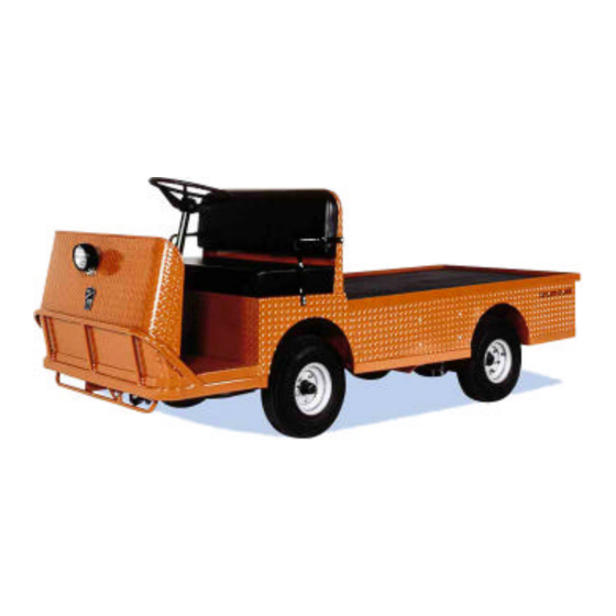
Related Manuals for Taylor-Dunn B0-248-48AC


Summary of Contents for Taylor-Dunn B0-248-48AC
- Page 1 Models Inlcuded: B0-248-48AC (B 2-48) B0-254-48AC (B 2-54) T h e B e s t W a y T o G o A b o u t Y o u r Equipped with AC Motor Speed Control B u s i n e s s...
- Page 3 Taylor-Dunn has a network of dealers distributed around the globe to support our vehicles. Information regarding vehicle sales, replacement parts, or service should be obtained through your local dealer. A dealer locator can be found on the Taylor-Dunn website at www.taylor-dunn.com.
- Page 4 B2-10 Ambulance B2-48 With Dump Bed Option B2-48 with Steel Cab, Foldaway 4-Passenger Seat and Stake Sides ET 3000 P2-50 30,000 Pound Tow Tractor ET1-50 Full Size Truck...
-
Page 5: Table Of Contents
Section Index Taylor-Dunn ® Model B0-248-48AC, B0-254-48AC Operator and Service Manual Section Index Introduction Safety Rules and Operating Instructions General Maintenance Front Axle Service Steering Component Service Brakes Service Transaxle Service Suspension Tires and Wheels Battery Service Wire diagram Control System Troubleshooting... - Page 6 SC1-00 Stock Chaser B2-48 With Stake Side Dump Bed Option E4-55 Sit Down Tow Tractor C4-25 Sit Down Tow Tractor...
- Page 7 Introduction Contents About this manual ......... 2 Who Should Read This Manual ....3 Responsibilities ..........3 How To Use This Manual ......4 Conventions ............. 5 How to Identify Your Vehicle ......6 B 2-48 and B 2-54 ........... 6 BT 2-48 ..............
-
Page 8: About This Manual
Please continue to read this manual and enjoy this high quality Taylor-Dunn ® vehicle. This manual is to serve as a guide for the service, repair, and operation of Taylor-Dunn ® vehicles and is not intended as a training guide. Taylor-Dunn ®... -
Page 9: Who Should Read This Manual
Of the Service Personnel... The service personnel are responsible for the service and maintenance of the vehicle. At no time should a service person allow any untrained personnel to service or repair this or any Taylor-Dunn ® vehicle. For the purposes of training, a qualified service person may oversee the repairs or services being made to a vehicle by an individual in training. -
Page 10: How To Use This Manual
INTRODUCTION HOW TO USE THIS MANUAL This manual is organized into five main sections: INTRODUCTION This section describes how to use this service manual and how to identify your vehicle. Safety Rules and Operating Instructions This section outlines the safety and operational issues, location and operation of controls, and the operational checks that are to be performed on this vehicle. -
Page 11: Conventions
INTRODUCTION Conventions Symbols and/or words that are used to define warnings, cautions, instructions, or notes found throughout this manual: A shaded box with the word “Warning” on its left denotes a warning. A warning alerts the reader of a hazard that may result in injury to themselves or others. -
Page 12: How To Identify Your Vehicle
INTRODUCTION HOW TO IDENTIFY YOUR VEHICLE This manual applies to vehicles with the same model and serial numbers listed on the front cover. These vehicles are designed for driving on smooth surfaces in and around facilities such as industrial plants, nurseries, institutions, motels, mobile home parks, and resorts. They are not to be driven on public highways. -
Page 13: Taking Delivery Of Your Vehicle
® distributor and report the problem. The report must be made within 24 hours of receiving the vehicle and its accessories. The only personnel authorized to repair, modify, or adjust any part of this or any Taylor-Dunn ® vehicle is a factory authorized service technician. - Page 14 SC1-00 Stock Chaser B2-48 With Stake Side Dump Bed Option E4-55 Sit Down Tow Tractor C4-25 Sit Down Tow Tractor...
- Page 15 Safety Rules and Operating Instructions TABLE OF CONTENTS Standard Specifications* ....... 2 Vehicle Operational Guidelines..... 10 Safety Rules and Guidelines ......3 Safety Guidelines ............. 10 Starting: ..............10 Driver Training Program ........ 4 While driving: ............10 Driver Qualifications..........4 Loading and Unloading ..........
-
Page 16: Standard Specifications
SAFETY RULES AND OPERATING INSTRUCTIONS STANDARD SPECIFICATIONS* ITEM Model SPECIFICATION Min/Max Battery 169 kg to 261 kg (372 lbs to 576 lbs) Weights Transmission Helical Gear, Oil Bath, Automotive Type Hypoid Differential Brakes Four Wheel Hydraulic Disc, Automaticaly Applied Park Brake Steering Automotive Steering 24:1 Frame... -
Page 17: Safety Rules And Guidelines
SAFETY RULES AND OPERATING INSTRUCTIONS SAFETY RULES AND GUIDELINES It is the responsibility of the owner of this vehicle to assure that the operator understands the various controls and operating characteristics of this vehicle (extracted from the American National Standards Institute Personnel and Burden Carriers ANSI B56.8). -
Page 18: Driver Training Program
SAFETY RULES AND OPERATING INSTRUCTIONS DRIVER TRAINING PROGRAM According to ANSI B56.8, the owner of this vehicle shall conduct an Operator Training program for all those who will be operating this vehicle. The training program shall not be condensed for those claiming to have previous vehicle operation experience. -
Page 19: Dash Up To Serial #179501
SAFETY RULES AND OPERATING INSTRUCTIONS VEHICLE CONTROLS DASH UP TO SERIAL #179501 1) Horn Switch The horn switch is located on the right side of the instrument panel. Depress the switch to sound the horn, release it to turn it off. 2) Forward-Off-Reverse Switch The forward-off-reverse switch, located on the right side of the instrument panel,... -
Page 20: Strobe Switch (Optional)
SAFETY RULES AND OPERATING INSTRUCTIONS DASH STARTING SERIAL #1795002 1) Headlight Switch The headlight switch is located on the top left of the instrument panel. Push the right side of the switch to turn the lights on. Push the left side of the switch to turn the light off. -
Page 21: Combination Display
SAFETY RULES AND OPERATING INSTRUCTIONS Combination Display The gauge on the dash has many functions. The display will cycle through the functions while the vehicle is in operation. Some functions may not be displayed depending on the current situation of the vehicle. Hour Meter Battery Status Speedometer... - Page 22 SAFETY RULES AND OPERATING INSTRUCTIONS Accelerator Pedal The accelerator pedal is located to the right of the brake pedal. It controls the speed of the vehicle and operates similar to the accelerator pedal in an automobile. Depress the pedal to increase speed and release the pedal to decrease speed.
-
Page 23: Charger Interlock
SAFETY RULES AND OPERATING INSTRUCTIONS Electrolyte Alarm (Optional) The Electrolyte Alarm is located in the battery area, in the 4th battery cell from the main battery positive cable. The Electrolyte alarm is activated when the battery cell fluid level falls below the level of the probe. The alarm is an audible continuous sound along with a bi-color indicator lamp. -
Page 24: Vehicle Operational Guidelines
SAFETY RULES AND OPERATING INSTRUCTIONS Starting: VEHICLE OPERATIONAL GUIDELINES 1. Make sure the forward-off-reverse witch is in the center “OFF” position. 2. Hold down the foot brake. Safety Guidelines 3. Insert the key and turn it to the “ON” position. 4. -
Page 25: Loading And Unloading
SAFETY RULES AND OPERATING INSTRUCTIONS Loading and Unloading Towing • This vehicle is equipped with a standard automatic Do not carry more than the maximum electric parking brake. The brake is automatically number of passengers allowed for this applied when the vehicle is stopped. There is a vehicle. -
Page 26: Adjustable Controller Parameters
SAFETY RULES AND OPERATING INSTRUCTIONS Adjustable Controller Parameters Model # B 2-48 equipped with 18:1 drive ratio Aceleration Parameters (normal mode) Function Value Unit Description Improper programming may cause unexpected Time to accelerate to ~15% of full FwdAS LS speed operation of the vehicle and/or damage the FwdAc HS Time to accelerate to full speed... - Page 27 SAFETY RULES AND OPERATING INSTRUCTIONS Model # B 2-48 / B 2-54 equipped with 30:1 drive ratio Aceleration Parameters (normal mode) Function Value Unit Description Time to accelerate to ~15% of full FwdAS LS speed FwdAc HS Time to accelerate to full speed Time to accelerate to from FwdAC LS RevAc LS to full...
-
Page 28: Charging Your Vehicle
SAFETY RULES AND OPERATING INSTRUCTIONS CHARGING YOUR VEHICLE Explosive mixtures of Hydrogen gas are present within battery cells at all times. Do not work with or charge battery in an area where open flames (including gas furnace or water heater pilots), sparks, cigarettes, or any other sources of combustion are present. -
Page 29: Signet Charger Operation, Model Hb Series
SAFETY RULES AND OPERATING INSTRUCTIONS Signet Charger Operation, Model HB Series The Signet ® HB series chargers use a semi-automatic charging system. The charger will turn itself ON when the AC power cord is connected to the AC power source and turn itself OFF when the batteries are fully charged. Refer to the data plate on the charger for the voltage and type power required for the charger. -
Page 30: Storing And Returning To Service
SAFETY RULES AND OPERATING INSTRUCTIONS To obtain the maximum battery life: Charge the batteries only after they reach a normal discharge as indicated on the Battery Status Indicator (BSI). Failure to follow this guideline could result in the batteries entering an overcharge state, which will reduce the life of the batteries. -
Page 31: Periodic Maintenance Checklist
SAFETY RULES AND OPERATING INSTRUCTIONS PERIODIC MAINTENANCE CHECKLIST NOTE: A full page copy of the Periodic Maintenance Safety Rules Page 17 Checklist is on the Vehicle Documentation CD under the [Misc] sub folder. -
Page 32: Daily Visual Inspection
SAFETY RULES AND OPERATING INSTRUCTIONS Daily Visual inspection: Tire condition and pressure. External frame damage (body). Operation of all lights and warning alarms and/or horns. Smooth and proper operation of all controls such as but not limited to: • Accelerator pedal, Brake pedal, Steering, Parking brake, etc. •... -
Page 33: General Maintenance
General Maintenance TABLE OF CONTENTS Maintenance Guidelines ....... 2 Troubleshooting Guide ........ 3 Lubrication Chart .......... 4... - Page 34 • Inspect and maintain battery limit switches, protective devices, electrical conductors, and ® connections in conformance with Taylor-Dunn’s recommended procedures. • Keep the vehicle in clean condition to minimize fire hazards and facilitate detection of loose or defective parts.
-
Page 35: Troubleshooting Guide
Maintenance, Service and Repair TROUBLESHOOTING GUIDE Symptom Probable Cause Front End Out of Alignment Steering Pulls in O ne Direction Low Tire Pressure Dry Lube Points in Steering Linkage Hard Steering Damaged King P in/Ball Joint Low Tire Pressure Worn Ball Joints Excessive Steering Play Mis-Adjusted or Worn Steering Gear Loose Steering Linkage... -
Page 36: Lubrication Chart
Maintenance, Service and Repair LUBRICATION CHART Rear Axle Lubrication Front End Lubrication Description Locations Lubricant Type Ball Joints General Purpose Grease Pedal Linkages General Purpose Grease Front Wheel Bearings High Temperature Wheel Bearing Grease King Pin General Purpose Grease Drive Drain Plug Drive Level Plug Drive Fill Plug SAE 80W90 Gear Oil... -
Page 37: Front Axle Service
Front Axle Service TABLE OF CONTENTS Inspect the Front Wheel Bearings and King Pin ........... 2 Adjust Front Wheel Bearings ....... 3 Front Axle Removal and Installation .... 4 Removal ..............4 Installation ..............5 Front Axle Disassembly ........ 6 Replace Front Wheel Bearings ..... -
Page 38: Inspect The Front Wheel Bearings And King Pin
Maintenance, Service, and Repair INSPECT THE FRONT WHEEL BEARINGS AND KING PIN 1. Make sure the key-switch is in the “OFF” position, then remove the key. 2. Place the forward-reverse switch in the center “OFF” position. 3. If equipped with a hand operated park brake, set the brake. 4. -
Page 39: Adjust Front Wheel Bearings
Maintenance, Service, and Repair ADJUST FRONT WHEEL BEARINGS 1. Make sure the key-switch is in the “OFF” position, then remove the key. 2. Place the forward-reverse switch in the center “OFF” position. 3. If equipped with a hand operated park brake, set the brake. 4. -
Page 40: Front Axle Removal And Installation
Maintenance, Service, and Repair FRONT AXLE REMOVAL AND INSTALLATION Removal 1. Make sure the key-switch is in the “OFF” position, then remove the key. 2. Place the forward-reverse switch in the center “OFF” position. 3. If equipped with a hand operated park brake, set the brake. 4. -
Page 41: Installation
Maintenance, Service, and Repair Installation 1. Make sure the key-switch is in the “OFF” position, then remove the key. 2. Place the forward-reverse switch in the center “OFF” position. 3. If equipped with a hand operated park brake, set the brake. 4. -
Page 42: Front Axle Disassembly
Maintenance, Service, and Repair FRONT AXLE DISASSEMBLY Disassembling and reassembling involves removing and replacing the left and right steering knuckles and king pin bushings. Refer to the following sections for information regarding these procedures: Replace the Steering Knuckle Replace the King Pins and Bushings NOTE: The front axle does not have to be removed unless the axle beam Front Axle Removal and must be replaced. -
Page 43: Replace Front Wheel Bearings
Maintenance, Service, and Repair REPLACE FRONT WHEEL BEARINGS 1. Make sure the key-switch is in the “OFF” position, then remove the key. 2. Place the forward-reverse switch in the center “OFF” position. 3. If equipped with a hand operated park brake, set the brake. 4. - Page 44 Maintenance, Service, and Repair 13. Install the hub dust cap. 14. Reinstall the brake body and the tire/wheel assembly. Brakes NOTE: Refer to the section for information regarding the installation of the brake body. 15. Lower the vehicle. 16. Reconnect the main positive and negative cables at the batteries. 17.
-
Page 45: Replace The King Pins And Bushings
Maintenance, Service, and Repair REPLACE THE KING PINS AND BUSHINGS There are different types of king pin bushings depending on the configuration of your vehicle. • Bronze bushings in the axle beam. • Bronze bushings in the steering knuckle. • Metal backed teflon bushings in the axle beam or suspension arm. - Page 46 Maintenance, Service, and Repair Replace the Steering Knuckle 7. Remove the steering knuckle. Refer to for information regarding removing the steering knuckle. NOTE: It is not necessary to remove the tie rod or drag link for this procedure. 8. Press the king pin bushings out from the axle, steering knuckle or suspension arm. 9.
-
Page 47: Replace The Steering Knuckle
Maintenance, Service, and Repair REPLACE THE STEERING KNUCKLE 1. Make sure the ON-OFF switch is in the “OFF” position, then remove the key. 2. Place the forward-reverse switch in the center “OFF” position. 3. If equipped with a hand operated park brake, set the brake. 4. - Page 48 Maintenance, Service, and Repair 12. Thoroughly clean and/or replace all bearings, nuts, washers, and bushings. NOTE: Both the left and right side bushings and thrust bearings should be replaced as a set. 13. Assemble in reverse order. 14. Pack the thrust bearing with grease. 15.
- Page 49 Steering Component Service TABLE OF CONTENTS Front End Alignment ........2 Inspect Ball Joints ......... 6 Inspect Rod Ends .......... 7 Adjust the Steering Gear ....... 8 Replace the Steering Shaft ......10 Replace the Steering Wheel ......12 Replace the Steering Gear ......13 Replace the Ball Joints, Tie Rods, and Drag Link ............
-
Page 50: Front End Alignment
Maintenance, Service, and Repair FRONT END ALIGNMENT This section will refer to two different types of ball joints. One type is has a grease fitting and a tapered shaft where it is fitted to the steering arm or pitman arm. The second type cannot be greased and has a straight shaft. - Page 51 Maintenance, Service, and Repair 10. At this point both the steering wheel and the front wheels should be tied up and held in position. If one or the other is not tied up then you must start from the beginning. Do not drive the vehicle while the steering wheel or front wheels are tied in position.
- Page 52 Maintenance, Service, and Repair Front wheel alignment NOTE: It is recommended to center the steering before aligning the front Center the Steering wheels. Refer to the section for information. 1. Make sure the key-switch is in the “OFF” position, then remove the key.
- Page 53 Maintenance, Service, and Repair 11. Measure the distance between the lines at the front Front Measurement of the tires. 12. Measure the distance between the lines at the rear of the tires. Sleeve Clamps 13. Adjust the tie rod so that the distance at the front and rear of the tires is the same.
-
Page 54: Inspect Ball Joints
Maintenance, Service, and Repair INSPECT BALL JOINTS NOTE: A set of ball joints and/or rod ends will wear at the same rate. If a ball joint and or rod end is worn out, then all should be replaced as a set. 1. -
Page 55: Inspect Rod Ends
Maintenance, Service, and Repair INSPECT ROD ENDS NOTE: A set of ball joints and/or rod ends will wear at the same rate. If a ball joint and or rod end is worn out, then all should be replaced as a set. 1. -
Page 56: Adjust The Steering Gear
Maintenance, Service, and Repair ADJUST THE STEERING GEAR NOTE: In some vehicle configurations it may be necessary to remove the Replace the steering gear to perform this procedure. Refer to Steering Gear for information regarding removing the steering gear. 1. Make sure the key-switch is in the “OFF” position, then remove the key. - Page 57 Maintenance, Service, and Repair 13. While rotating the input shaft back and forth through its centered position, adjust the gear lash adjusting screw so that there is a slight drag as the steering gear is rotated through its centered position. 14.
-
Page 58: Replace The Steering Shaft
Maintenance, Service, and Repair REPLACE THE STEERING SHAFT 1. Make sure the key-switch is in the “OFF” position, then remove the key. 2. Place the forward-reverse switch in the center “OFF” position. 3. If equipped with a hand operated park brake, set the brake. 4. - Page 59 Maintenance, Service, and Repair 11. Remove the steering shaft from the vehicle. 12. Lightly grease the input shaft splines, steering wheel splines and the upper steering shaft bushing. 13. Install the steering shaft in reverse order using a new pinch bolt. Orientate the shaft so that the pinch bolt is opposite the flat in the steering gear shaft.
-
Page 60: Replace The Steering Wheel
Maintenance, Service, and Repair REPLACE THE STEERING WHEEL 1. Make sure the key-switch is in the “OFF” position, then remove the key. 2. Place the forward-reverse switch in the center “OFF” position. 3. If equipped with a hand operated park brake, set the brake. 4. -
Page 61: Replace The Steering Gear
Maintenance, Service, and Repair REPLACE THE STEERING GEAR 1. Make sure the key-switch is in the “OFF” position, then remove the key. 2. Place the forward-reverse switch in the center “OFF” position. 3. If equipped with a hand operated park brake, set the brake. 4. -
Page 62: Replace The Ball Joints, Tie Rods, And Drag Link
Maintenance, Service, and Repair REPLACE THE BALL JOINTS, TIE RODS, AND DRAG LINK This section will refer to two different types of ball joints. One type is has a grease fitting and a tapered shaft where it is installed on the steering arm or pitman arm. The second Rod End cannot be greased and has a straight shaft. - Page 63 Maintenance, Service, and Repair 10. Install the new rod end into the steering sleeve. Screw it into the sleeve the same number of turns counted in the previous step. Do not tighten the rod end clamp or jam nut at this time. 11.
-
Page 64: Replacing The Drag Link
Maintenance, Service, and Repair 12. Install the ball joint into the steering arm. Tighten the ball joint nut to 40-45 ft-lbs. and install a new cotter pin. 13. Realign the front wheels. Steering NOTE: Refer to the section for information regarding realignment of the front wheels. -
Page 65: Replacing The Tie Rod
Maintenance, Service, and Repair 11. Lower the vehicle. 12. Reconnect the main positive and negative cables at the batteries. 13. Remove the blocks from behind the wheels. 14. Release the park brake and test drive the vehicle. Replacing the Tie Rod The Tie Rod is the linkage that connects the two steering knuckles together. -
Page 66: Center The Steering Gear
Maintenance, Service, and Repair CENTER THE STEERING GEAR 1. Remove the pitman arm. 2. Rotate the input shaft clockwise until it stops. 3. While counting the rotations, rotate the input shaft counter clockwise until it stops. 4. Rotate the input shaft clockwise 1/2 the rotations counted in the previous step. 5. -
Page 67: Repair The Steering Gear
Maintenance, Service, and Repair REPAIR THE STEERING GEAR Disassembly NOTE: The steering gear must be removed from the vehicle for this procedure. Refer to Replace the Steering Gear section for information regarding removing the steering gear. NOTE: The steering gear is packed with grease. Only perform maintenance on the steering gear in an area that will contain any grease that may spill out of the steering gear when it is disassembled. - Page 68 Maintenance, Service, and Repair 4. Remove the worm shaft and ball nut assembly from the bottom of the housing. 5. Remove the worm shaft seal. 6. Remove the pitman shaft seal. 7. Remove the upper worm bearing and bearing cup from the housing.
- Page 69 Maintenance, Service, and Repair 9. Place the upper worm bearing on the worm shaft and install the worm shaft/ball nut assembly into the housing being careful not to damage the worm shaft seal. 10. Install the assembled worm bearing adjuster into the housing and tighten just enough to remove all play in the worm shaft.
-
Page 70: Exploded View Of Steering Gear
Maintenance, Service, and Repair Exploded View of Steering Gear Steering Page 22... -
Page 71: Brakes Service
Brake Service TABLE OF CONTENTS Inspect the Service Brake ......2 Disc Brake Pads ............2 Disc Brake Rotor ............3 Inspect the Automatic Parking Brake ..4 Adjust the Automatic Parking brake .... 4 Adjust the Service Brakes ......4 Two or Four Wheel Hydraulic Disc Brakes .... -
Page 72: Inspect The Service Brake
Maintenance, Service, and Repair INSPECT THE SERVICE BRAKE Disc Brake Pads Current Taylor-Dunn brakes are asbestos free. However, there is the ® possibility that the original brakes were replaced with aftermarket parts containing asbestos. Since this possibility exists, all brake parts should be handled as if they contain asbestos. -
Page 73: Disc Brake Rotor
Maintenance, Service, and Repair Disc Brake Rotor Current Taylor-Dunn brakes are asbestos free. However, there is ® the possibility that the original brakes were replaced with aftermarket parts containing asbestos. Since this possibility exists, all brake parts should be handled as if they contain asbestos. Refer to Appendix C for recommended handling precautions. -
Page 74: Inspect The Automatic Parking Brake
Maintenance, Service, and Repair INSPECT THE AUTOMATIC PARKING BRAKE The parking brake is located inside of the motor and is electromagnetically operated. To inspect operation of the parking brake, disconnect the harness to the parking brake and push the vehicle to confirm that the brake is applied. -
Page 75: Check Master Cylinder Fluid
Maintenance, Service, and Repair CHECK MASTER CYLINDER FLUID Do not ingest brake fluid or allow contact with skin or eyes. Always wear protective clothing and a face shield when working with or around brake fluid. SKIN CONTACT Flush area immediately with water for several minutes. If a rash or skin irritation develops, get medical attention immediately. -
Page 76: Bleed The Brake System
Maintenance, Service, and Repair BLEED THE BRAKE SYSTEM Do not ingest brake fluid or allow contact with skin or eyes. Always wear protective clothing and a face shield when working with or around brake fluid. SKIN CONTACT Flush area immediately with water for several minutes. If a rash or skin irritation develops, get medical attention immediately. - Page 77 Maintenance, Service, and Repair 7. Add brake fluid from a new sealed container to the master cylinder. Fill to 1/4” from the top of the master cylinder chamber. • Only use DOT 3 brake fluid from a new sealed container. •...
-
Page 78: Flush The Brake System
Maintenance, Service, and Repair FLUSH THE BRAKE SYSTEM 1. Make sure the key-switch is in the “OFF” position, then remove the key. 2. Place the forward-reverse switch in the center “OFF” position. 3. If equipped with a hand operated park brake, set the brake. 4. -
Page 79: Replace Front Disc Brake Pads
REPLACE FRONT DISC BRAKE PADS NOTE: It is recommended that both the left and right brake pads be replaced as a set. Current Taylor-Dunn brakes are asbestos free. However, there is ® the possibility that the original brakes were replaced with aftermarket parts containing asbestos. - Page 80 Maintenance, Service, and Repair NOTE: Refer to the illustration above for the following steps. 10. Remove the brake body bolts (10) and discard the lock nuts (1) and brake pads (8). 11. Remove the spacer bushings (6) from the mounting bracket (5) and discard the bushings. Inspect the Service Brakes 12.
-
Page 81: Replace Rear Brake Pads
Maintenance, Service, and Repair REPLACE REAR BRAKE PADS Hydraulic Disc Current Taylor-Dunn brakes are asbestos free. However, there is ® the possibility that the original brakes were replaced with aftermarket parts containing asbestos. Since this possibility exists, all brake parts should be handled as if they contain asbestos. - Page 82 Maintenance, Service, and Repair 9. Remove the tire/wheel assembly. Tires and Wheels NOTE: Refer to section for information on removing the tire and wheel assembly. 10. Release the park brake (wheel brake only). 11. Remove the brake body bolts and discard the lock nuts and brake pads. 12.
-
Page 83: Replace The Wheel Cylinder
Maintenance, Service, and Repair REPLACE THE WHEEL CYLINDER Disc Brake Body Assembly (front or rear) Current Taylor-Dunn brakes are asbestos free. However, there is ® the possibility that the original brakes were replaced with aftermarket parts containing asbestos. Since this possibility exists, all brake parts should be handled as if they contain asbestos. - Page 84 Maintenance, Service, and Repair Tires and Wheels 8. Remove the tire/wheel assembly. Refer to section for information on removing the tire and wheel assembly. 9. Thoroughly clean the area around the brake body. 10. Remove the brake body bolts and discard the lock nuts.
-
Page 85: Replace The Master Cylinder
Maintenance, Service, and Repair REPLACE THE MASTER CYLINDER Do not ingest brake fluid or allow contact with skin or eyes. Always wear protective clothing and a face shield when working with or around brake fluid. SKIN CONTACT Flush area immediately with water for several minutes. If a rash or skin irritation develops, get medical attention immediately. - Page 86 Maintenance, Service, and Repair 10. Install in reverse order. 11. Adjust the master cylinder push rod so that it is Plunger approximately 1/8 inch away from the master cylinder plunger when the brake pedal is up. 12. Fill the master cylinder with brake fluid from a sealed container.
-
Page 87: Repair The Master Cylinder
Maintenance, Service, and Repair REPAIR THE MASTER CYLINDER NOTE: Hydraulic brake system components must be kept clean. Make sure your work area is free from dirt and debris and will contain any brake fluid spills. Remove the master cylinder from the vehicle. See Replace the Master Cylinder section . Drain all fluid from the master cylinder and discard. - Page 89 Transmission TABLE OF CONTENTS Check Oil Level ..........2 Change Oil ............. 3 Motor Removal and Installation ....4 Rear Hub or Rotor ......... 5 Removing and Installing the Rear Axles (Disc Brakes) ........... 6 Transmission Assembly ....... 8 Remove and Install ........... 8 Disassembly and Reassembly of the Primary Reduction Gear Case ......
-
Page 90: Check Oil Level
Maintenance, Service, and Repair CHECK OIL LEVEL The oil flows freely between the main gear case (3rd member) and the primary reduction gear case. It is only necessary to check the oil level of the 3rd member. Park the vehicle on a level surface. 1. -
Page 91: Change Oil
Maintenance, Service, and Repair CHANGE OIL 1. Make sure the key-switch is in the “OFF” position, then remove the key. 2. Place the forward-reverse switch in the center “OFF” position. 3. If equipped with a hand operated park brake, set the brake. 4. -
Page 92: Motor Removal And Installation
Maintenance, Service, and Repair MOTOR REMOVAL AND INSTALLATION NOTE: Some applications will require removing the drive assembly from Removing and the vehicle to remove the motor. Refer to Installing the Drive Assembly for information on removing the drive assembly. Some vehicles are equipped with an automatic electric brake. The automatic electric brake is sandwiched between the drive motor and the gear case. -
Page 93: Rear Hub Or Rotor
Maintenance, Service, and Repair REAR HUB OR ROTOR NOTE: The torque specification for the axle hub bolt is 275 ft-lbs. An impact wrench will be required to remove the bolt. NOTE: The axle hub bolt has a special thread locking compound applied to the threads. -
Page 94: Removing And Installing The Rear Axles (Disc Brakes)
Maintenance, Service, and Repair REMOVING AND INSTALLING THE REAR AXLES (DISC BRAKES) The oil level in the housing is above the bottom of the axle flange. To minimize oil spills, raise the side of the vehicle high enough so that the oil level is below the bottom of the axle flange. - Page 95 Maintenance, Service, and Repair 11. Remove the axle retaining plate and brake body assembly as one unit. 12. Secure the brake body assembly, do not let it hang by the brake hose. 13. Pull the axle out of the housing. 14.
-
Page 96: Transmission Assembly
Maintenance, Service, and Repair TRANSMISSION ASSEMBLY Remove and Install 1. Make sure the key-switch is in the “OFF” position, then remove the key. 2. Place the forward-reverse switch in the center “OFF” position. 3. If equipped with a hand operated park brake, set the brake. 4. -
Page 97: Disassembly And Reassembly Of The Primary Reduction Gear Case
Maintenance, Service, and Repair DISASSEMBLY AND REASSEMBLY OF THE PRIMARY REDUCTION GEAR CASE 1. Make sure the key-switch is in the “OFF” position, then remove the key. 2. Place the forward-reverse switch in the center “OFF” position. 3. If equipped with a hand operated park brake, set the brake. 4. - Page 98 Maintenance, Service, and Repair 12. Remove the circlip from the idler gear. 13. Remove the input shaft/bearing assembly and idler gear/ bearing assembly from the gear case cover at the same time. 14. Remove the pinion nut from the output gear and remove the output gear from the pinion shaft.
- Page 99 Maintenance, Service, and Repair Lubricate all parts with gear oil before installation. Failure to pre-lube the parts may result in premature failure. 19. Assemble the gear case in reverse order. NOTE: Torque the drain plug to 21-25 foot-pounds. NOTE: Torque the gear case to 3rd member retaining bolts to 18-20 foot- pounds.
-
Page 100: Disassembling The 3Rd Member
Maintenance, Service, and Repair DISASSEMBLING THE 3RD MEMBER 1. Make sure the key-switch is in the “OFF” position, then remove the key. 2. Place the forward-reverse switch in the center “OFF” position. 3. If equipped with a hand operated park brake, set the brake. 4. - Page 101 Maintenance, Service, and Repair 13. Remove the carrier bearing adjusting nut roll pin and adjusting nut from the side plate. 14. Turn the side plate over and remove the carrier bearing race from the side plate. 15. Remove the differential assembly from the 3rd member housing.
- Page 102 Maintenance, Service, and Repair 17. Remove the carrier bearing race from the 3rd member housing. 18. Remove the front bearing from the input shaft. NOTE: The input shaft may have to be driven out to perform this procedure. 19. Remove the input shaft’s shims and spacer. 20.
-
Page 103: Assembling The 3Rd Member
Maintenance, Service, and Repair ASSEMBLING THE 3RD MEMBER 1. Temporarily install the pinion gear (hand tighten only). 2. Install the carrier bearing race ring nuts into the housing and cover. Cover Housing 3. Install the carrier bearing races into the housing and cover. Cover Housing 4. - Page 104 Maintenance, Service, and Repair 10. Mark the position of each carrier bearing ring nut in relation to the drive housing and cover and then remove the differential assembly, do not allow the ring nuts to rotate. 11. Install the pinion gear. Re-shim if required. If the ring and pinion gears or bearings are replaced then the pinion gear must be re-shimmed.
- Page 105 Maintenance, Service, and Repair 17. Install the locking roll pins into the housing and cover to lock the ring nuts in place. 18. Remove the pinion gear holding tool. 19. Install the primary reduction gear case, axles and housings, motor, and install the complete drive onto the vehicle.
-
Page 106: Pinion Bearing Preload
Maintenance, Service, and Repair Pinion Bearing Preload NOTE: The pinion gear depth must be set before the preload. Refer to Setting the Pinion Gear Depth 1. Install the pinion gear, spacer, and shims into the housing. 2. Install the outer pinion bearing. 3. -
Page 107: Pinion Gear Shimming Instructions
Maintenance, Service, and Repair PINION GEAR SHIMMING INSTRUCTIONS NOTE: This procedure is required only when replacing the front or rear pinion bearings and races or the ring and pinion gears. NOTE: To perform this procedure, all parts must be clean and the bearings lightly lubricated. - Page 108 Maintenance, Service, and Repair NOTE: Values shown are for reference only Transmission Page 20...
-
Page 109: Suspension
Suspension TABLE OF CONTENTS Replace the Rear Springs ......2 Replace the Front Springs ......3 Replace the Spring Bushings ....... 4 Replace the Shocks ........5... -
Page 110: Replace The Rear Springs
Maintenance, Service, and Repair REPLACE THE REAR SPRINGS If a spring has failed or is fatigued, then it is recommended that both rear springs are replaced as a set. HINT : In most vehicles it will be easier if the springs are replaced one at a time. -
Page 111: Replace The Front Springs
Maintenance, Service, and Repair REPLACE THE FRONT SPRINGS If a spring has failed or is fatigued, then it is recommended that both front springs are replaced as a set. HINT : In most vehicles it will be easier if the springs are replaced one at a time. -
Page 112: Replace The Spring Bushings
Maintenance, Service, and Repair REPLACE THE SPRING BUSHINGS It is recommended that all front spring bushings are replaced as a set. Your vehicle will be equipped with one of two types of spring bushings, internal and external (see illustration to the right): •... -
Page 113: Replace The Shocks
Maintenance, Service, and Repair REPLACE THE SHOCKS It is recommended to replace all shocks as a set. NOTE: On some vehicles it may be required to remove the front wheel to gain access to the shock mounting bolts. Refer to Tires and Wheels section for information regarding removing the front wheels. - Page 115 Tires and Wheels TABLE OF CONTENTS Tire Inflation ..........2 Tire Inspection ..........2 Replace the Tire/Wheel ......... 3 Repair the Tire (pneumatic) ......4 Replace the Tire (pneumatic) ....... 5...
-
Page 116: Tire Inflation
Maintenance, Service, and Repair TIRE INFLATION 1. Make sure the key-switch is in the “OFF” position, then remove the key. 2. Place the forward-reverse switch in the center “OFF” position. 3. Set the park brake. 4. Place blocks under the front wheels to prevent vehicle movement. 5. -
Page 117: Replace The Tire/Wheel
Maintenance, Service, and Repair 8. Inspect for uneven tire wear on the front tires. Uneven tire wear could be a result of an improperly inflated tire or a misaligned or damaged front end. NOTE: Refer to Tire Inflation section or Steering Component Service section for information on proper tire inflation or front end wheel alignment. -
Page 118: Repair The Tire (Pneumatic)
Maintenance, Service, and Repair 4-Bolt Pattern 5-Bolt Pattern 8-Bolt Pattern Pattern for tightening the wheel nuts Re-torque all wheel nuts to their final value after 1-week (20-hours) of operation. Failure to re-torque the wheel nuts may result in the wheel coming off of the vehicle causing severe bodily injury and/or property damage. -
Page 119: Replace The Tire (Pneumatic)
Maintenance, Service, and Repair REPLACE THE TIRE (PNEUMATIC) NOTE; To replace the tire, the tire/wheel assembly must be removed from Replace the Tire/Wheel the vehicle. Refer to section for information on removing the tire/wheel assembly. Explosion Hazard. Fully deflate the tire before attempting to remove the tire from the wheel. -
Page 121: Battery Service
Battery Service TABLE OF CONTENTS Cleaning ............2 Testing ............3 Watering ............5 Charging ............6 Replacing (6-volt batteries only) ....7 Moist Charge Batteries ..........9 Storage and Returning to Service ....10 Storage ..............10 Returning to Service ..........11... -
Page 122: Cleaning
Maintenance, Service, and Repair CLEANING Explosive mixtures of Hydrogen gas are present within battery cells at all times. Do not work with or charge battery in an area where open flames (including gas furnace or water heater pilots), sparks, cigarettes, or any other sources of combustion are present. Always provide ample ventilation in rooms where batteries are being charged. -
Page 123: Testing
Maintenance, Service, and Repair TESTING NOTE: A combination of the Load Test and Specific Gravity Test should be used to accurately determine the condition of the batteries. Explosive mixtures of Hydrogen gas are present within battery cells at all times. Do not work with or charge battery in an area where open flames (including gas furnace or water heater pilots), sparks, cigarettes, or any other sources of combustion are present. - Page 124 Maintenance, Service, and Repair Specific Gravity Test NOTE: The batteries must be fully charged before performing this test. The specific gravity of a cell is an indication of the actual state of charge of the cell. A fully charged cell should have a reading of 1275 to 1300 (see the illustration to the right).
-
Page 125: Watering
Maintenance, Service, and Repair WATERING NOTE: The electrolyte level in a battery rises while charging and will be close to its highest level after the end of a charging cycle. It is recommended to fill the batteries at the end of a charging cycle. If the electrolyte is below the top of the battery plates then fill just enough to cover the plates and then top off when the charging cycle is complete. -
Page 126: Charging
Maintenance, Service, and Repair 1. Make sure the key-switch is in the “OFF” position, then remove the key. 2. Place the forward-reverse switch in the center “OFF” position. 3. Set the park brake. 4. Place blocks under the front wheels to prevent vehicle movement. 5. -
Page 127: Replacing (6-Volt Batteries Only)
Maintenance, Service, and Repair REPLACING (6-VOLT BATTERIES ONLY) Explosive mixtures of Hydrogen gas are present within battery cells at all times. Do not work with or charge battery in an area where open flames (including gas furnace or water heater pilots), sparks, cigarettes, or any other sources of combustion are present. - Page 128 Maintenance, Service, and Repair 7. Remove the battery hold downs. 8. Inspect the battery hold downs for corrosion. If any signs of corrosion are seen then the battery hold downs should be replaced. 9. Remove all battery jumpers from both posts of the battery or batteries being replaced. NOTE: It is recommended to replace the battery jumpers when replacing the batteries.
-
Page 129: Moist Charge Batteries
Maintenance, Service, and Repair Moist Charge Batteries Explosive mixtures of Hydrogen gas are present within battery cells at all times. Do not work with or charge battery in an area where open flames (including gas furnace or water heater pilots), sparks, cigarettes, or any other sources of combustion are present. -
Page 130: Storage And Returning To Service
Maintenance, Service, and Repair 6. Fill all battery cells with electrolyte to the proper level. 7. Thoroughly clean any spilled electrolyte from the Cleaning the batteries or the ground. Refer to Batteries for information on cleaning the batteries. 8. Reconnect the battery cables, connect the batteries to the charger and allow the charger to complete one charging cycle. -
Page 131: Returning To Service
Maintenance, Service, and Repair Returning to Service Explosive mixtures of Hydrogen gas are present within battery cells at all times. Do not work with or charge battery in an area where open flames (including gas furnace or water heater pilots), sparks, cigarettes, or any other sources of combustion are present. - Page 133 The vehicle wiring diagram is too large to be legible when printed at this size. A full size diagram (22 x 16) is included on the CD in PDF format. You can access the diagram from a button on the CD menu. The diagram # is: SCH-00007 for vehicles with 12 volt accessory tap.
- Page 135 Control System Diagnostics TABLE OF CONTENTS Test Equipment Required: ...... 2 Important Notes and Instructions ... 2 Status LED Code Table ......3 Throttle Module Test ......6 Rev C...
-
Page 136: Test Equipment Required
Electrical Troubleshooting Test Equipment Required: • User Level Maintenance Handset part number 62-027-64 The Maintenance Handset can view current faults, fault history, monitor all controller inputs and outputs and monitor the current status of the controller, motor, battery and vehicle operation. Instruction for using the handset are included with the handset. -
Page 137: Status Led Code Table
Electrical Troubleshooting Status LED Code Table The status LED’s on the speed controller can be used to give you an idea of where the problem may be. During normal operation (no faults) the yellow LED will be flashing steady. When the controller senses a fault the two LED’s can be used to determine the fault code. - Page 138 Electrical Troubleshooting Code Handset Display Possible Cause Note Effect of Fault Battery failure. Overvoltage Cutback High voltage generated Reduced brake torque. during normal regen. Faulty motor encoder. +5-volt supply at Pin - +5-volt Supply Failure Faulty wiring 26 is too low None.
- Page 139 Electrical Troubleshooting Code Handset Display Possible Cause Note Effect of fault See note, voltage too low on pin-17 Not used – If fault occurs Brake Wiper Low then check controller Full brake. connector for contamination Current into pin-18 exceeded 0.010A Not used –...
-
Page 140: Throttle Module Test
Electrical Troubleshooting Throttle Module Test 1. Make sure the key-switch is in the “OFF” position, then remove the key. 2. Place the forward-reverse switch in the center “OFF” position. 3. Set the park brake. 4. Place blocks under the front wheels to prevent vehicle movement. Disconnect both of the battery leads during any maintenance or before disconnecting any electrical component or wire. - Page 141 TABLE OF CONTENTS Operating Instructions and Theory of Operation ......2 Testing the Charging Cycle ....3 Test Equipment Required for Troubleshooting ......4 Important Notes and Instructions -------------------- 4 Troubleshooting for Built-in Charger ..5 Troubleshooting for Portable Charger ..8 Testing The Timer Relay ......9 Testing the Interlock Relay .....10 Turn the Key switch OFF BEFORE disconnecting the batteries.
-
Page 142: Wire Diagram
Electrical Troubleshooting OPERATING INSTRUCTIONS AND THEORY OF OPERATION The Lestronic II ® chargers are designed as semiautomatic chargers. The Lestronic II ® charger turns itself on when the “built- in” charger is plugged into the wall outlet, or when the “portable” charger is plugged into the batteries. - Page 143 Electrical Troubleshooting TESTING THE CHARGING CYCLE In typical installations, the charger will remain on for up to 12 hours depending on the state of charge of the battery when the charge cycle was started. A charger could remain on for longer than 12 hours if: •...
- Page 144 Electrical Troubleshooting TEST EQUIPMENT REQUIRED FOR TROUBLESHOOTING Digital Multi Meter (DMM) with diode and capacitor test function, FLUKE 79 ® model shown at right and in the troubleshooting illustrations. Important Notes and Instructions • This troubleshooting guide assumes a familiarity with the use of a digital multimeter including, voltage tests, continuity tests and diode testing.
- Page 145 Electrical Troubleshooting TROUBLESHOOTING FOR BUILT-IN CHARGER 1. Make sure the key-switch is in the “OFF” position, then remove the key. 2. Place the forward-reverse switch in the center “OFF” position. 3. Set the park brake. 4. Place blocks under the front wheels to prevent vehicle movement. 5.
- Page 146 Electrical Troubleshooting • Disconnect the charger from the AC source. • Disconnect the batteries. • Disconnect the charger from the vehicle’s harness. • Remove the charger from the vehicle. HIGH VOLTAGE may be stored in the capacitor. Discharge the capacitor before continuing.
- Page 147 Electrical Troubleshooting • Test the voltage from the fuse assembly (-) to the diode block (+). This voltage should be equal to the battery voltage. If the voltage is less than the battery voltage, then the wires from the harness connectors to the charger are bad.
- Page 148 Electrical Troubleshooting TROUBLESHOOTING FOR PORTABLE CHARGER Disconnect the charger from the AC outlet and the batteries. 1. Test the voltage from the positive terminal on the vehicles DC receptacle to main battery negative. This voltage should be equal to the battery voltage. If the voltage is less than the battery voltage then this wire is broken or has a bad connection.
- Page 149 Electrical Troubleshooting 5. Reconnect the lead to the diode. 6. Connect the charger to the AC source. Insert the DC charger plug into the DC receptacle and perform the following tests: High Voltage inside the charger. Do not touch any internal components while the charger is plugged in.
- Page 150 Electrical Troubleshooting 4. Disconnect the wires from the contact terminals on the timer relay. 5. Reconnect the batteries. 6. Wait 5 seconds, then test the continuity across the timer relay contact terminals. • If this is a closed circuit, then the timer start up circuit is functioning normally. •...
- Page 151 TABLE OF CONTENTS Operating Instructions and Theory of Operation ........2 HB/PT and GEL Indicator Lamps ...3 Testing the Charging Cycle ....3 Test Equipment Required for Troubleshooting .......4 Important Notes and Instructions Status LED Error Code Table ....5 Troubleshooting ........6 Turn the Key switch OFF BEFORE disconnecting the batteries.
- Page 152 Electrical Troubleshooting OPERATING INSTRUCTIONS AND THEORY OF OPERATION ® ® The model HB600W and HB1000W chargers are designed as semiautomatic chargers. The charger turns itself on when it is plugged into the wall outlet and turns off when the batteries are fully charged.
- Page 153 Electrical Troubleshooting HB/PT AND GEL INDICATOR LAMPS NOTE: Your charger may not be equipped with these lamps. HB/PT Lamp If the HB/PT lamp is “ON”, then the charger has overheated and has entered a proportionally reduced output. The charging cycle will terminate if the temperature continues to rise.
- Page 154 Electrical Troubleshooting TEST EQUIPMENT REQUIRED FOR TROUBLESHOOTING ® Digital Multi Meter (DMM), FLUKE 79 model shown at right and in the troubleshooting illustrations. Clamp on DC ammeter to measure up to 20-Amps. Important Notes and Instructions • This troubleshooting guide assumes a familiarity with the use of a digital multimeter including, voltage tests, continuity tests and diode testing.
- Page 155 Electrical Troubleshooting STATUS LED ERROR CODE TABLE There are three status lights (LED’s) on the charger name plate. These LED’s normally indicate the current operating state of the charger. If all three LED’s are flashing, it indicate an error has occurred in the charging cycle.
- Page 156 Electrical Troubleshooting TROUBLESHOOTING To test charger operation: Connect a DC volt meter to the main battery positive and negative terminals. Attach a clamp on DC Ammeter to one of the charger DC output wires. Plug the charger into an AC outlet. Wait for charger to start (up to15 seconds), the ammeter should display the DC Amp rating of the charger (plus or minus 10%) indicating that the charger is on (constant current mode).
- Page 157 Charger Models: HBS 600 HBS 1000 TABLE OF CONTENTS Definitions: ..........2 Test Equipment Required for Troubleshooting .......2 Important Notes and Instructions Operating Instructions and Theory of Operation ........3 Testing the Charging Cycle ....4 Status Light Error Code Table....5 Troubleshooting ........6 Turn the Key switch OFF BEFORE disconnecting the batteries.
-
Page 158: Clamp On Dc Ammeter To Measure Up To 20-Amps
Electrical Troubleshooting DEFINITIONS: Volts Per Cell = Voltage for each cell in a battery pack. for example, one 6-volt battery has 3-cells. Term Value Condition V1: Voltages are temperature compensated See Chart Flooded batteries relative to the temperature of the charger at the 2.383 Volts Per Cell Gel Batteries time the charge cycle is started. - Page 159 Electrical Troubleshooting OPERATING INSTRUCTIONS AND THEORY OF OPERATION Typical specification plate (reference only, specifications will vary for different chargers) ® ® The model HBS 600W and HBS 1000W chargers are designed as automatic chargers. The charger turns itself on when it is plugged into the wall outlet and turns off when the batteries are fully charged. Once the charging cycle is complete, the charger will monitor the battery voltage.
- Page 160 Electrical Troubleshooting TESTING THE CHARGING CYCLE In typical installations, The charge cycle will be completed in 8 to 12 hours depending on the state of charge of the batteries when the charge cycle was started. NOTE: The charge cycle time is limited to 20-hours (max). A fault will occur if charging time exceeds the time limit.
- Page 161 Electrical Troubleshooting STATUS LIGHT ERROR CODE TABLE If the Fault light is ON or flashing, it indicates a problem has occured during the charging cycle. If the light is flashing, it will flash from 2 to 6 times before a pause. This is the fault code. Refer to the table below.
- Page 162 Electrical Troubleshooting TROUBLESHOOTING NOTE: There are no internally serviceable components in the charger. To test charger operation: Connect a DC volt meter to the main battery positive and negative terminals. Attach a clamp on DC Ammeter to one of the charger DC output wires. Plug the charger into an AC outlet.
- Page 163 Illustrated Parts TABLE OF CONTENTS Front Axle ............ 2 Miscellaneous Electrical ......32 Steering Knuckle ......... 4 Lighting ............34 Steering Linkage ......... 6 Lestronic® Charger (page 1) ....... 36 Steering Column .......... 8 Lestronic® Charger (page 2) ....... 38 Front Suspension ........
-
Page 164: Front Axle
Illustrated Parts Front Axle Parts Page 2... - Page 165 Illustrated Parts Front Axle ITEM # PART # DESCRIPTION 15-049-71 Axle Beam, B 2-48, BT 2-48, B 2-54 15-050-76 Complete axle assembly See following pages for component breakdowns Parts Page 3...
-
Page 166: Steering Knuckle
Illustrated Parts Steering Knuckle Parts Page 4... - Page 167 Illustrated Parts Steering Knuckle ITEM # PART # DESCRIPTION 88-239-86 3/4-NF Hex Slotted Nut 88-228-60 3/4 Cut Flat Washer 98-603-07 Rubber Bushing 01-220-99 Washer 32-240-44 Bushing 32-240-43 Bushing 80-309-12 Thrust Bearing 45-338-00 Grease Seal 80-017-00 Tapered Bearing 80-103-00 Tapered Bearing Race 12-158-10 Wheel Hub W/Rotor (incl 1-#12, 1-#11, 1-#13) 88-228-61...
-
Page 168: Steering Linkage
Illustrated Parts Steering Linkage Parts Page 6... - Page 169 Illustrated Parts Steering Linkage ITEM # PART # DESCRIPTION 18-041-05 Tie rod, B 2-48, B 2-54, BT 2-48 86-510-00 Ball joing clamp 86-501-98 Ball joing (left) 86-501-99 Ball joint (right) 88-527-11 1/8 x 1 Cotter pin 18-057-11 Drag link 88-159-85 1/2NF Castle nut 18-104-00 Pitman Arm...
-
Page 170: Steering Column
Illustrated Parts Steering Column The steering column is an integral part of the frame and is not shown. Part ID# 5 is located in the top of the steering column tube. Ref., Steering Gear Parts Page 8... - Page 171 Illustrated Parts Steering Column ITEM # PART # DESCRIPTION 88-199-82 5/8NF Hex nut 19-011-20 Steering wheel 88-081-14 5/16NF x 1-1/2 Hex bolt, grade 8 88-089-84 5/16NF Hex lock nut, grade C 32-248-10 Upper bushing 20-031-65 Steering shaft assembly (incl. 3 and 4) 19-011-25 Steering wheel cap 88-128-62...
-
Page 172: Front Suspension
Illustrated Parts Steering Gear Front Suspension Front axle (ref) Parts Page 10... - Page 173 Illustrated Parts Steering Gear 18-308-21 ITEM # PART # DESCRIPTION 18-308-70 Locknut 18-308-71 Adjuster assembly 18-308-72 Worm assenbly 18-308-23 Upper worm bearing 18-308-22 Upper worm bearing race 18-308-77 Housing 18-308-78 Seal, pitman shaft 18-308-80 Nut, pitman shaft 18-308-81 Lock washer 18-308-79 Seal, input shaft 18-308-82...
-
Page 174: Rear Suspension
Illustrated Parts Rear Suspension View from rear Parts Page 12... - Page 175 Illustrated Parts Rear Suspension ITEM # PART # DESCRIPTION 96-240-00 1/2NC x 4 Spring bolt (front of the leaf spring) Not shown 32-214-50 Spring bushing (front of the leaf spring) 85-510-17 Leaf spring 16-861-46 Spring mounting plate (left) 16-861-47 Spring mounting plate (right) 96-114-00 U-bolt 88-159-84...
-
Page 176: Transmission Gear Case
Illustrated Parts Transmission Gear Case Parts Page 14... - Page 177 Illustrated Parts Transmission Gear Case ITEM # PART # DESCRIPTION GT-71682 M8 x 60 bolt GT-3287563 Gear case cover GT-71259 Bearing GT-3287513 Input shaft, 30:1 0 or 1 GT-3287523 Input shaft, 24:1 0 or 1 GT-3287533 Input shaft, 18:1 0 or 1 GT-71982 O-ring GT-3287503...
-
Page 178: Rear Axle
Illustrated Parts Rear Axle Outer Bearing Inner Bearing (no o-ring) Axle Shaft O-Ring O-Ring Groove Inner bearing on optional double bearing axle does not have an oil seal or o-ring. Orientation of bearing should have o-ring groove adjacent to o-ring on outer bearing. - Page 179 Illustrated Parts Rear Axle ITEM # PART # DESCRIPTION 41-154-20 Axle shaft (single bearing) 41-154-25* *Axle shaft (double bearing) 80-505-20 Bearing 80-505-30* *Bearing (for double bearing axle) 41-490-11 Disc brake rotor 41-172-21 88-268-63 Flat washer 88-268-30 7/8-14 x 1.5 Bolt, grade 5 96-329-10 Wheel stud 92-104-10...
-
Page 180: Rear Brakes
Illustrated Parts Rear Brakes Front Brakes Parts Page 18... -
Page 181: Front Brake
Illustrated Parts Rear Brakes ITEM # PART # DESCRIPTION 99-588-00 Bleeder valve 99-588-01 Bleeder adaptor 41-348-70 Brake pad Brake body assembly (not available as a replcement component) 32-240-41 Bushing 41-348-57 Spacer 88-067-21 Bolt 88-069-82 97-126-05 Flat Washer 41-350-28 Mounting bracket 96-327-10 3/8X3/4,NF,2A THD,GRD5,LOC (brake bracket to drive) Not Shown... -
Page 182: Brake Lines
Illustrated Parts Brake Lines Master Cylinder Parts Page 20... - Page 183 Illustrated Parts Brake Lines ITEM# PART # DESCRIPTION 99-609-61 Brake Line, front brakes 99-603-73 Brake Line, regen switch to brake switch 99-606-51 Brake Line, Front Right 99-603-72 Brake Line, brake switch to rear brakes 99-603-70 Brake Line, Rear Right 99-603-71 Brake Line, Rear Left 99-580-20 Brake Hose, Rear...
-
Page 184: Motor
Illustrated Parts Motor Parts Page 22... - Page 185 Illustrated Parts 70-059-41 Motor Spec # ZFB40SO/4 DF100L-4 ITEM # PART # DESCRIPTION 41-354-05 Brake 70-400-14 Snap ring 70-400-12 Fan Shroud 70-400-11 70-400-15 O-ring 70-400-16 70-400-17 Snap ring 70-400-21 70-400-18 Snap ring 70-400-19 Snap ring 70-400-13 Seal 70-400-09 Rubber Grommet Terminal stud Hex nut Washer...
-
Page 186: Motor Mount
Illustrated Parts Motor Mount Apply 94-421-34 grease to inside of motor coupler Parts Page 24... - Page 187 Illustrated Parts MOTOR MOUNT ITEM # PART # DESCRIPTION See Motor Motor 96-114-12 U-bolt 80-714-05 O-ring 88-068-62 1/4 Split lock wahser 89-060-11 6mm x 1.0 x 50 Hex bolt 89-111-27 10mm x 1.5 x 20 Hex bolt 88-128-62 7/16 Split lock washer 70-456-03 Mounting bracket 88-067-17...
-
Page 188: Wheels And Tires
Illustrated Parts Wheels and Tires Ref., wheel hub 5 (assembly) Parts Page 26... - Page 189 Illustrated Parts Wheels and Tires ITEM # PART # DESCRIPTION 94-423-20 FLAT OUT,TIRE SEAL,PT BOTL Wheels 12-012-00 5 x 8" Tubeless 12-020-00 8.5 x 8 Tubeless 12-050-00 12-1/8 Diameter Cast Iron Tires 10-083-00 5.70 x 8 LR C 10-092-00 8.50 x 8 LR C 10-260-00 18 X 5 X 12 1/8 Solid rubber Split Rim Wheels...
-
Page 190: Instrument Panel Up To Serial # 179501
Illustrated Parts Instrument Panel Up To Serial # 179501 Instrument Panel Starting Serial # 179502 Parts Page 28... - Page 191 Illustrated Parts Instrument Panel Up To Serial # 179501 ITEM # PART # DESCRIPTION 71-102-15 Horn switch 71-039-02 F&R switch Light switch 71-039-11 High / Low speed switch 74-010-20 Gauge, Spy Glass 71-100-00 Auxiliary switchs 0, 1, 2 71-120-00 Start switch (standard) 71-119-99 Spacer 71-121-20...
-
Page 192: Speed Control Panel
Illustrated Parts Speed Control Panel B 2-48 shown Wire Harnesses PART # DESCRIPTION 75-153-08 Dash harness 75-153-04 Cable, Spy Glass 75-153-07 Main control h1arness 75-153-05-60 Control panel 75-153-06 Power Parts Page 30... -
Page 193: Resetting The Maintenance Meter Function
Illustrated Parts Speed Control Panel ITEM # PART # DESCRIPTION 73-005-01 Motion alarm 62-400-35* Motor speed control, B 2-48 62-400-11* Motor speed control, B 2-54 89-080-16 8mm x 1.25 x 16mm Hex bolt 89-060-17 8mm Lock washer 02-425-17 Controller base, 1/4 plate 02-425-18 Mounting panel 79-844-20... -
Page 194: Miscellaneous Electrical
Illustrated Parts Miscellaneous Electrical Accelerator Module Seat Frame Motion Alarms Seat Interlock Switch Miscellaneous Wire Harness Clamps Parts Page 32... - Page 195 Illustrated Parts Miscellaneous Electrical ITEM # PART # DESCRIPTION 98-599-15 Plastic grommet for 1.75 hole 98-599-20 Plastic Grommet for 2.5 hole 75-107-10 Potratble Charger Harness Not Shown JF3-86181-00-00 Portable Charger Receptacle 72-015-00 Dome light (optional) 78-321-10 (optional) 75-105-25 Harness, Dome light 73-005-05 Reverse Warning alarm 96-650-01...
-
Page 196: Lighting
Illustrated Parts Lighting Stobe Light Parts Page 34... - Page 197 72-023-23 Red lens Not shown 72-023-21 Replacement bulb * -There are many special order types of mounting configurations. Contact your Taylor-Dunn distributor with the serial number of the vehcle for more information. Head and Tail Lights ITEM # PART #...
-
Page 198: Lestronic® Charger
Illustrated Parts Lestronic® Charger (page 1) Parts Page 36... - Page 199 Illustrated Parts Parts Page 37...
- Page 200 Illustrated Parts Lestronic® Charger (page 2) Parts Page 38...
- Page 201 Illustrated Parts Parts Page 39...
-
Page 202: Signet® Charger
Illustrated Parts Signet® Charger Model HBS series charger shown Model HBS for Flooded Batteries Model HB for Flooded Batteries PART # DESCRIPTION PART # DESCRIPTION 24 volt Charger Assembly (see note) 79-302-20 24 volt Charger Assembly (see note) 79-303-41 36 volt Charger assembly (see note) 79-303-40 36 volt Charger assembly (see note) 79-309-42... -
Page 203: Portable Charger Wiring
Illustrated Parts Portable Charger Wiring PART # DESCRIPTION 75-107-10 HRNSS,PORTABLE/LESS CHRGER JF3-86181-00-00 RECEPTACLE, W/INTERLOCK 90157-05M19-00 92907-05100-00 Mounting hardware for receptacle 92907-05600-00 98507-05035-00 Parts Page 41... -
Page 204: Batteries
Illustrated Parts Batteries Main Negative Main Positive 12 Volt Negative tap Parts Page 42... - Page 205 88-089-70 5/16 Split lock washer, stainless steel 77-055-15 Battery wattering system for Trojan batteries (optional) 77-055-12 Battery wattering system for Exide or Taylor-Dunn batteries (optional) Not shown 77-055-13 BATTERY FILLING GUN, used with watering systems (optional) 01-534-43 Battery locator (angle in bottom of battery box) Quantities depend on voltage configuration of vehicle.
-
Page 206: Seat Cushions And Deck
Illustrated Parts Seat Cushions and Deck Parts Page 44... - Page 207 Illustrated Parts Seats and Deck ITEM # PART # DESCRIPTION 90-148-00 Passenger seat cushion (standard) 90-172-00 Passenger seat cushion (with steel cab) 90-140-00 Seat back (standard) 90-179-00 Seat back (with steel cab) 90-142-00 Seat back (1/2 cowl frame) 90-148-00 Driver seat cushion (standard) 90-172-00 Driver seat cushion (with steel cab) 90-444-00...
-
Page 208: Mirrors
Illustrated Parts Mirrors 92-202-00 Assembly Miscellaneous Frame Components Parts Page 46... - Page 209 79-511-00 Charger AC cord holder 79-530-00 Charger AC cord strain releif 79-575-25 Charger cord, Lester charger only 30-807-00 COVER,STEERING GEAR SUPT 94-201-00 TAYLOR-DUNN EMBLEM 88-567-91 Clip for TD Emblem 01-110-20 Throttle pedal 98-200-00 Rubber brake pedal pad Parts Page 47...
-
Page 210: Decals
Illustrated Parts Decals Parts Page 48... - Page 211 Illustrated Parts Decals ITEM # PART # DESCRIPTION 94-319-00 Battery disconnect 1 or 2 94-313-00 Battery warning 1 or 2 94-373-10 Vehicle identification 94-384-21 Brake warning 94-313-20 Safety warning 94-384-01 Not a motor vehicle 94-384-14 When leaving vehicle warning 94-301-41 Brake fluid 94-384-17 Do not wash...
-
Page 212: Cab Options
Illustrated Parts Cab Options Steel Cab Fiberglass cab Parts Page 50... - Page 213 Illustrated Parts Steel Cab ITEM # PART # DESCRIPTION 91-012-00 Steel cab (unpainted) 90-852-30 Front windshield 90-850-10 Rear window 98-310-00 Rubber windshield gasket (by the foort) Fiberglass Cab ITEM # PART # DESCRIPTION 91-000-00 Fiberglass cab 90-800-00 Front windshield 90-850-00 Rear window 98-310-10 Rubber windshiel gasket (by the foot)
-
Page 214: Door Options, Steel Cab
Illustrated Parts Door Options, Steel Cab 29,12 11,12 Steel door detail Note: Left Door Shown Door frame Door frame Door Restraint Parts Page 52... - Page 215 Illustrated Parts Cab Doors Naugahyde (Steel cab) ITEM # PART # DESCRIPTION 90-923-98 Door Frame, Left Not shown 90-923-99 Door Frame, Right 90-924-98 Side Curtain, Left Not shown 90-924-99 Side Curtain Right 97-315-53 Handle Assembly, Outer 97-315-51 Door Latch 97-315-54 Handle Assembly Inside 97-303-03 Snap Fastner...
-
Page 216: Door Options, Fiberglass Cab
Illustrated Parts Door Options, Fiberglass Cab Typical door assembly Parts Page 54... - Page 217 Illustrated Parts Cab Doors Naugahyde (fiberglass cab) ITEM # PART # DESCRIPTION 90-921-98 Door Frame, Left 90-921-99 Door Frame, Right 98-451-11 Weather seal tape (by the foot) 90-908-98 Side Curtain, Left 90-908-99 Side Curtain Right 97-315-53 Handle Assembly, Outer 97-315-51 Door Latch 97-315-54 Handle Assembly Inside...
-
Page 218: Hydraulic Dump Body Option
Illustrated Parts Hydraulic Dump Body Option Parts Page 56... - Page 219 Illustrated Parts Dump Bed Option ITEM # PART # DESCRIPTION 21-018-00 Cylinder Pin 88-060-11 Bolt, 1/4 X 1-1/4" NC, Hex Head 88-069-81 Locknut, 1/4" NC 21-019-00 Shaft, Dump Bed Pivot 17-112-00 Collar, Shaft 99-524-00 Hydraulic Cylinder 99-957-00 Hydraulic Pump and Motor 99-597-09 Bracket, Hydraulic Pump 88-100-11...
-
Page 220: Rear Cargo Box
Illustrated Parts Rear Cargo Box Top Covers Parts Page 58... - Page 221 Illustrated Parts Rear Cargo Box ITEM # PART # DESCRIPTION 91-333-02 Cargo box (unpainted) 90-471-00 Front deck board 90-472-00 Rear deeck board 90-850-10 Front window 98-310-00 Ruber window gasket (by the foor) 90-851-00 Rear window Not shown 94-320-10 Load line decal 00-210-23 Deck support angle Top Covers...
-
Page 222: Hitches
Illustrated Parts Hitches Parts Page 60... -
Page 223: Ladder Rack Option B2-004-66 And B2-006-78
Illustrated Parts Trailer Hitches ITEM # PART # DESCRIPTION 97-811-00 1-7/8 inch Ball 97-821-00 2-inch Ball 88-140-14 1/2NC x 1-1/2 Hex bolt 88-149-80 1/2NC Hex nut 88-148-62 1/2 Split lock washer Ladder Rack Option B2-004-66 and B2-006-78“ NOTE: Replacement parts only. Ladder rack cannot be added to an existing vehicle PART # DESCRIPTION... -
Page 225: Brake Lining Handling Precautions
Contents Appendix A: Special Tools ....2 Appendix B: Suggested Torque Limits for Standard Hardware ..3 Hardware Identification ...... 3 Standard Head Markings ........3 Hex Bolts .............. 3 Other Bolts ............3 Hex Nuts ............... 4 Hex Lock Nuts (stover) ........4 Other Nuts ............. -
Page 226: Appendix A: Special Tools
Appendixes APPENDIX A: SPECIAL TOOLS DESCRIPTION PURPOSE PART # Used for testing electrical circuits. Powered by the Test Light truck batteries, switchable for 12, 24, 36, and 48 62-027-00 volts. Used to test the solid state accellerator module Accelerator Test Harness 62-027-31 part number series 62-033-XX. -
Page 227: Hex Bolts
Appendixes APPENDIX B: SUGGESTED TORQUE LIMITS FOR STANDARD HARDWARE HARDWARE IDENTIFICATION Standard Head Markings NOTE: Torque value used should be for lowest grade of hardware used. If a grade 2 nut is used on a grade 8 bolt, use grade 2 torque value. NOTE: Toque values specified are for clean dry threads. -
Page 228: Hex Nuts
NOTE: Nuts with no markings are to be treated as S.A.E. Grade A S.A.E. Grade B S.A.E. Grade C Grade L’9 Other Nuts Other nuts used by Taylor-Dunn should be treated as S.A.E. grade A ® Appendixes Appendix B Page 4... -
Page 229: Suggested Torque Values (Non-Critical Hardware)
Appendixes Suggested Torque Values (non-critical hardware) Diameter Grade 2 Grade 5 Grade 8 and TPI Tightening Tightening Tightening Tightening Torque Torque Torque Torque (ft-lb) (ft-lb) (ft-lb) (ft-lb) 1/4-20 7-10 10-14 1/4-28 8-12 11-16 5/16-18 9-14 14-21 20-29 5/16-24 10-15 15-23 22-33 3/8-16 16-24... - Page 230 Appendixes Suggested Torque Values (critical hardware) Torque Table Torque Range Group Description Ft-Lbs In-Lbs Brakes - - - - - - - - - - - - - - - - - - - - - - - - Brake bolt (disc brake body) 11 - 11 132 - 132 15 - 15...
-
Page 231: Appendix C: Brake Lining Handling Precautions
Appendixes APPENDIX C: BRAKE LINING HANDLING PRECAUTIONS Taylor-Dunn does not currently supply asbestos fiber-brake pads/ shoes with any vehicle. However, there is the possibility that the original brake pads/shoes were replaced with aftermarket pads/shoes containing asbestos. Since this possibility does exist, the brake pads/ shoes should be handled as if they do contain asbestos. - Page 232 Taylor-Dunn Mfg. ® 2114 W. Ball Rd. Anaheim, CA 92804 (800)-688-8680 (714) 956-4040 (FAX) (714) 956-0504 Mailing Address: P.O. Box 4240 Anaheim, California 92803 Visit our Website: www.taylor-dunn.com...
Need help?
Do you have a question about the B0-248-48AC and is the answer not in the manual?
Questions and answers