Table of Contents
Advertisement
Quick Links
A S S E M B L Y M A N U A L
" Graphics and speci cations may change without notice " .
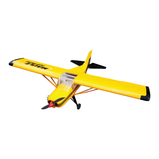
Code: SEA232
Speci cations:
Wingspan---------------70.9 in (180 cm).
Wing area---------------810.3 sq.in (52.3 sq.dm).
Weight-------------------9.0 lbs (4.1 kg).
Length-------------------47.4 in (120.5 cm).
Engine-------------------10cc - 15cc.
Glow engine------------.61-.91 - 2 stroke
Motor size---------------Power 60
Radio--------------------6 channels with 8 servos.
Electric conversion: Optional.
1
Advertisement
Table of Contents

Related Manuals for Seagull Models SEA232


Summary of Contents for Seagull Models SEA232
- Page 1 A S S E M B L Y M A N U A L “ Graphics and speci cations may change without notice ” . Code: SEA232 Speci cations: Wingspan---------------70.9 in (180 cm). Wing area---------------810.3 sq.in (52.3 sq.dm). Weight-------------------9.0 lbs (4.1 kg).
-
Page 2: Kit Contents
Maule SUPER ROCKET Instruction Manual. INTRODUCTION. ank you for choosing the MAULE SUPER ROCKET ARF by SG MODELS . e MAULE SUPER ROCKET was designed with the intermediate/advanced sport yer in mind. It is a semi scale airplane which is easy to y and quick to assemble. e airframe is conventionally built using balsa, plywood to make it stronger than the average ARF, yet the design allows the aeroplane to be kept light. -
Page 3: Additional Items Required
KIT CONTENTS. HINGING THE FLAP. SEA232 MAULE SUPER ROCKET SEA23201 Fuselage SEA23202 Wing set SEA23203 Tail set SEA23204 Canopy SEA23205 Pilot SEA23206 Cowling SEA23207 Aluminum wing tube ADDITIONAL ITEMS REQUIRED. M2x10mm 10-15cc gasoline engine. .61-.91 glow engine. Power 60 size motor. -
Page 4: Hinging The Aileron
Maule SUPER ROCKET Instruction Manual. Hinge. 3) Slide the wing panel on the aileron until there is only a slight gap. e hinge is now centered on the wing panel and aileron. Re- move the T-pins and snug the aileron against the wing panel. -
Page 5: Hinging The Rudder
5) Turn the wing panel over and de ect the HINGING THE RUDDER. aileron in the opposite direction from the opposite side. Apply thin C/A glue to each Glue the top two rudder hinges in place hinge, making sure that the C/A penetrates using the same techniques used to hinge into both the aileron and wing panel. - Page 6 Maule SUPER ROCKET Instruction Manual. INSTALL ELEVATOR CONTROL HORN. Epoxy. Fiberglass control horn. Aileron control horn. INSTALL FLAP CONTROL HORN. Install the ap control horn using the same method as same as the aileron con- trol horns. Epoxy. Elevator berglass control horn. Fiberglass control horn.
-
Page 7: Installing The Fuselage Servos
rottle servo. Epoxy. e back of fuselage. THROTTLE SERVO ARM INSTALLATION. Install adjustable servo connector in the servo arm as same as picture below: Loctite secure. Adjustable servo connector. Rudder berglass control horn. INSTALLING THE FUSELAGE SERVOS. Servo arm. Because the size of servos di er, you may need to adjust the size of the precut ¡... - Page 8 Maule SUPER ROCKET Instruction Manual. INSTALLING THE RECEIVER SWITCH. Install the switch into the precut hole in the side, in the fuselage. 3/32” Hole. Switch. INSTALLING THE STOPPER ASSEMBLY. 1) Using a modeling knife, carefully cut o the rear portion of one of the 3 nylon tubes leaving 1/2”...
-
Page 9: Fuel Tank Installation
¢ £ ¤ ¥ ¥ ¦ § £ ¨ © ¦ £ ¦ ¥ ¦ § £ ¨ © ¦ £ ¥ ¦ § £ ¨ 8) Use plywood template to hold in place the fuel tank with C/A glue to secure the fuel 3) Carefully bend the second nylon tube up tank inside the fuselage. -
Page 10: Mounting The Engine
Maule SUPER ROCKET Instruction Manual. Vent tube. Fuel ll tube. read locker glue. Fuel pick up tube. 9) Connect the lines from the tank to the en- MOUNTING THE ENGINE. gine and mu er. e vent line will connect to the mu er and the line from the clunk to 1) Position the engine with the drive the carburetor. - Page 11 Machine screw M4x30mm 4) On the re wall has the location for the throttle pushrod tube (pre-drill). 8) Reinstall the servo horn by sliding the connector over the pushrod wire. Cent- 5) Slide the pushrod tube in the rewall er the throttle stick and trim and install and guide it through the fuel tank mount.
- Page 12 Maule SUPER ROCKET Instruction Manual. Cut. Because of the size of the cowl, it may be nec- essary to use a needle valve extension for the high speed needle valve. Make this out of suf- COWLING. cient length 1.5mm wire and install it into the end of the needle valve.
- Page 13 - Motor: 50mm 310-500 kV - Propeller: 14x10 ~ 15x10 - ESC: 60A - Lipo Batteries: 5-6 cell 4000-5000mAh 3) Attach the electric motor box to the rewall suitable with the cross lines drawn on the electric motor box and rewall.
- Page 14 Maule SUPER ROCKET Instruction Manual. Epoxy 145 mm Balsa stick. 4 mm Epoxy 5) Attach the speed control to the side of the motor box using two-sided tape and tie wraps. Connect the appropriate leads from the speed control to the mo- tor.
-
Page 15: Installing The Aileron Servos
INSTALLING THE AILERON SERVOS. Battery. INSTALLING THE SPINNER. Install the spinner backplate, propeller £ " £ & ¥ and spinner cone. ¨ ¨ & £ Because the size of servos di er, you may need to adjust the size of the precut opening in the mount. - Page 16 Maule SUPER ROCKET Instruction Manual. 3) Use drill bit in a pin vise to drill the mouting holes in the blocks. C/A glue 8) Remove the string from the wing at the servo location and use the tape to at- tach it to the servo extension lead.
Need help?
Do you have a question about the SEA232 and is the answer not in the manual?
Questions and answers