Table of Contents
Advertisement
Advertisement
Table of Contents

Related Manuals for Aritech 1X-X3E Series


Summary of Contents for Aritech 1X-X3E Series
- Page 1 1X-X3E Series Operation Manual P/N 501-419303-2-10 • REV 01 • ISS 17MAR14...
- Page 2 Copyright © 2014 UTC Fire & Security. All rights reserved. Trademarks and 1X-X3E Series is a trademark of UTC Fire & Security. patents Other trade names used in this document may be trademarks or registered trademarks of the manufacturers or vendors of the respective products.
-
Page 3: Table Of Contents
The user interface 3 Operator controls and indicators 4 Audible indicators 11 Control panel status indications 11 Control panel operation 18 User levels 18 Public user level operation 18 Operator user level operation 20 Maintenance 28 Regulatory information 29 1X-X3E Series Operation Manual... -
Page 4: Important Information
Installation in accordance with this manual, applicable codes, and the instructions of the authority having jurisdiction is mandatory. While every precaution has been taken during the preparation of this manual to ensure the accuracy of its contents, UTCFS assumes no responsibility for errors or omissions. 1X-X3E Series Operation Manual... -
Page 5: Introduction
Introduction This is the operation manual for the 1X-X3E Series Extinguishing and Fire Alarm Control Panel. Read these instructions and all related documentation entirely before operating this product. The control panel provides three fire detection zones (Z1, Z2, and Z3) and several manual call point (MCP) inputs that control the extinguishing actions for a single extinguishing area. - Page 6 An alarm in a zone not linked to the extinguishing area or event triggers a fire alarm. In this state, fire sounders and other system features or devices are activated after any configured delay. No extinguishing alarms or devices are activated. 1X-X3E Series Operation Manual...
-
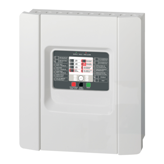
Page 7: Control Panel Overview
30. Fire Routing Delay button and LED [1] 15. General Test button and LED 31. Fire Routing On button and LEDs [1] [1] Fire routing is only available if a 2010-1-SB expansion board is installed and fire routing functionality is configured. 1X-X3E Series Operation Manual... -
Page 8: Operator Controls And Indicators
Steady red LEDs indicate that the fire alarm was activated by a fire manual call point. For alarms from fire detection zones, the corresponding zone alarm LED indicates the source or location of the fire alarm. 1X-X3E Series Operation Manual... - Page 9 A flashing yellow LED indicates a wiring fault on the extinguishing sounders (or, if configured, sounder outputs in expansion modules linked to the activation or released states). A steady yellow LED indicates a disablement or test. 1X-X3E Series Operation Manual...
- Page 10 Consult your system installer to determine whether your system has this option configured. Networking Fault Yellow Indicates a networking fault. Networking is optional. Consult your system installer to determine whether your system has this option configured. 1X-X3E Series Operation Manual...
- Page 11 A steady red LED indicates that the extinguishing agent was released out of its container and into the extinguishing area. A flashing yellow LED indicates an open or short circuit wiring fault. A steady yellow LED indicates a disablement or test. 1X-X3E Series Operation Manual...
- Page 12 21. Numeric keypad and Used to enter the operator level password. Enter button The Enter button is also used to disable or test selected features (when pressed with the General Disable or Test button). 1X-X3E Series Operation Manual...
- Page 13 A steady upper yellow LED indicates that the extinguishing switch extinguishing switch is disabled. (BS 7273) A flashing lower yellow LED indicates an open or short circuit wiring fault. A steady lower yellow LED indicates a disablement or test. 1X-X3E Series Operation Manual...
- Page 14 A flashing red LED indicates that fire routing is activated. A flashing yellow LED indicates a wiring fault. A steady yellow LED indicates a disablement or a test. Consult your system installer to determine whether the Fire routing option is configured. 1X-X3E Series Operation Manual...
-
Page 15: Audible Indicators
Flashing when a delay countdown is in progress. Fire sounders are activated when the configured delay elapses or when the delay is cancelled. Off when the fire sounders are off (or will be deactivated shortly). 1X-X3E Series Operation Manual... - Page 16 Fire Sounders Start/Stop LED: Steady, as the fire sounders are activated immediately and any configured delay is bypassed. • Fire routing indications are shown in the usual manner, linked to the fire alarm event. The control panel buzzer sounds continuously. 1X-X3E Series Operation Manual...
- Page 17 Flashing slowly if the actuator has been activated and the control panel is waiting for confirmation of the flow of the extinguishing agent. Consult your system installer to determine whether your system has this option configured. 1X-X3E Series Operation Manual...
- Page 18 • The actuator output to release the extinguishing agent has been activated and the agent flow has been confirmed, when agent flow confirmation is configured. • The agent flow is configured and activated. 1X-X3E Series Operation Manual...
- Page 19 General Disable LED and a steady yellow Extinguishing Sounders On LED. • Disabled fire sounders are indicated by a steady General Disable LED and a steady yellow Fire Sounders Delay LED. 1X-X3E Series Operation Manual...
- Page 20 Extinguishing agent pressure monitoring tests are indicated by a steady General Test LED and a steady yellow Low Pressure LED. Extinguishing released optical warning panel or sign tests are indicated by a steady General Test LED and a steady yellow Optical Panel On LED. 1X-X3E Series Operation Manual...
- Page 21 (The Out of Service state is latched.) Note: When the control panel indicates out of service, the fire alarm detection in your system is inactive and your site is not protected. Contact your installation or maintenance contractor immediately to solve the problem. 1X-X3E Series Operation Manual...
-
Page 22: Control Panel Operation
Public user level operation lets you: • Acknowledge a system event and silence the control panel buzzer • Cancel an active fire sounders delay • Cancel an active fire routing delay • Perform a control panel LED and buzzer test 1X-X3E Series Operation Manual... - Page 23 The control panel buzzer sounds continuously. The test continues for as long as the Test button remains pressed (with an automatic timeout of 12 seconds). When the test is completed the control panel returns to its former state. 1X-X3E Series Operation Manual...
-
Page 24: Operator User Level Operation
Reset button may remain disabled for up to 30 minutes. Consult your system installer for the time configured. When the Reset LED is steady the control panel can be reset. 1X-X3E Series Operation Manual... - Page 25 The extinguishing sounder tone depends on the extinguishing status (extinguishing activation or extinguishing released) and the system configuration. Normally, this tone is intermittent for activation and continuous for released. Consult your system installer to determine whether these default settings are used for your site. 1X-X3E Series Operation Manual...
- Page 26 Sounders Delay button. To enable the delay, press the button again. If an alarm is reported in a zone linked to the extinguishing event, any configured delay will be ignored and fire sounders will be activated immediately. 1X-X3E Series Operation Manual...
- Page 27 A steady General Test LED • A steady yellow Fire Routing On LED • A flashing Fire Routing On LED and the test signal (3 seconds on, 5 seconds off) without any configured delay for the duration of the test 1X-X3E Series Operation Manual...
- Page 28 If there is an alarm in another zone not in test, or if the MCP Start is activated, the control panel responds to the alarm event as configured. Note: The control panel buzzer and sounders may be configured not to sound when an alarm is activated in a zone being tested. 1X-X3E Series Operation Manual...
- Page 29 Door monitor [2] Door Fault/Disabled Pressure switch monitoring Low Pressure yellow Extinguishing agent flow monitoring Extinguishing Agent Flow yellow Extinguishing release optical warning panel/sign Optical Panel On yellow Start extinguishing manual call points MCP Start yellow 1X-X3E Series Operation Manual...
- Page 30 Disable extinguishing Ext. disabled switch A steady ext. disabled LED indicates that the switch (yellow) input has been activated. The activation of any input under test will not activate any associated functionality. 1X-X3E Series Operation Manual...
- Page 31 MCP Start point can generate the extinguishing event. In addition, the control panel can be set to manual-only or manual-automatic mode using the key switch, if your installer has configured this option. 1X-X3E Series Operation Manual...
-
Page 32: Maintenance
Keep the outside and inside of the control panel clean. Carry out periodic cleaning using a damp cloth for the outside. Do not use products containing solvents to clean the unit. Do not clean the inside of the cabinet with liquid products. 1X-X3E Series Operation Manual... -
Page 33: Regulatory Information
Emergency hold device (mode A or B) 4.21 Control of flooding time 4.23 Manual mode 4.24 Trigger signals to equipment within the system 4.26 Trigger signals to equipment outside the system 4.27 Emergency abort device 4.30 Activate alarm devices with different signals 1X-X3E Series Operation Manual... - Page 34 European standards for electrical safety and electromagnetic compatibility These control panels have been designed in accordance with the following European standards for electrical safety and electromagnetic compatibility: • EN 60950-1 • EN 50130-4 • EN 61000-6-3 • EN 61000-3-2 • EN 61000-3-3 1X-X3E Series Operation Manual...
Need help?
Do you have a question about the 1X-X3E Series and is the answer not in the manual?
Questions and answers