Table of Contents
Advertisement
Quick Links
Advertisement
Chapters
Table of Contents

Related Manuals for Aritech 1X-X3


Summary of Contents for Aritech 1X-X3
- Page 1 1X-X3 Installation Manual P/N 501-419003-1-11 • REV 01.10 • ISS 11NOV13...
- Page 2 Copyright © 2013 UTC Fire & Security. All rights reserved. Trademarks and The 1X-X3 name and logo are trademarks of UTC Fire & Security. patents Other trade names used in this document may be trademarks or registered trademarks of the manufacturers or vendors of the respective products.
-
Page 3: Table Of Contents
Power supply specifications 63 Mechanical and environmental specifications 64 Appendix A Configuration presets 67 Input and output configuration 68 Default delays 68 Basic configuration modes 68 Expansion board functions 69 Appendix B Regulatory information 73 European standards 74 Index 77 1X-X3 Installation Manual... -
Page 4: Important Information
Important information This is the installation manual for the 1X-X3 Extinguishing and Fire Alarm Control Panel. Read these instructions and all related documentation entirely before operating this product. Software compatibility Information in this document applies to control panels with software version 1.0 or later. - Page 5 Installation in accordance with this manual, applicable codes, and the instructions of the authority having jurisdiction is mandatory. While every precaution has been taken during the preparation of this manual to ensure the accuracy of its contents, UTCFS assumes no responsibility for errors or omissions. 1X-X3 Installation Manual...
- Page 6 1X-X3 Installation Manual...
-
Page 7: Introduction
Chapter 1 Introduction Summary This chapter provides an introduction to your control panel and the available operating modes Content Product description 2 Product compatibility 2 1X-X3 Installation Manual... -
Page 8: Product Description
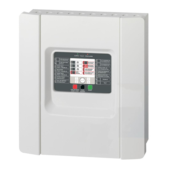
Chapter 1: Introduction Product description The 1X-X3 control panel provides three fire detection zones (Z1, Z2, and Z3) and several manual call point (MCP) and control inputs that control the extinguishing actions for a single extinguishing area. If a fire detection zone is not configured as part of the extinguishing detection area, the control panel provides standard fire panel functionality for that fire detection zone. -
Page 9: Installation
Fixing the cabinet to the wall 5 Connections 7 Recommended cables 7 Connecting zones with initiating devices 7 Connecting inputs 10 Connecting outputs 14 Connecting the mains power supply 16 Connecting the batteries 18 Connecting other equipment 18 1X-X3 Installation Manual... -
Page 10: Control Panel Cabinet Layout
Note: The control panel is available with an access key option. The key switch is located on the panel cover. With this option, either the key or the password can be used to enter the operator user level. 1X-X3 Installation Manual... -
Page 11: Cabinet Installation
Fixing the cabinet to the wall Fix the cabinet to the wall using five M4 × 30 screws and five 6 mm diameter wall plugs, as shown below. 1X-X3 Installation Manual... - Page 12 2. Drill all required holes and insert a 6 mm wall plug into each. 3. Insert a screw in position (1) and hang the cabinet onto this screw. 4. Insert screws in positions (2) and tighten. 5. Insert screws in position (3) and tighten. 6. Tighten screw in position (1). 1X-X3 Installation Manual...
-
Page 13: Connections
Z2 and Z3, both as mixed zones. Option 2 — Z1 and Z2. This is the default configuration). Both Z1 and Z2 must be in alarm to initiate an extinguishing event. Z3 provides standard fire detection as a mixed zone. 1X-X3 Installation Manual... - Page 14 55 Ω max. To measure the line resistance: 1. Disconnect all zone devices. 2. Create a short circuit at the end of the zone line. 3. Measure the resistance between the positive and negative lines with a multimeter. 1X-X3 Installation Manual...
- Page 15 The resistance required depends on the zone type, as shown in the table below. Table 4: Fire alarm manual call point resistance values Zone type Resistance [1] Mixed detection 100 Ω Manual detection 100 to 680 Ω [1] Resistance must be rated at 1 W minimum. 1X-X3 Installation Manual...
-
Page 16: Connecting Inputs
If a supervised input is not used, the end-of-line resistor must be installed across the unused terminals. Connecting inputs Connect inputs IN1 to IN8 as shown below. Figure 4: Connecting inputs Refer to the topic “Input and output specifications” on page 61 for the input circuit parameters. 1X-X3 Installation Manual... - Page 17 The MCP Hold LED turns off when the MCP Hold device is deactivated. See “Hold mode” on page 38 for instructions on setting the MCP Hold operating mode. 1X-X3 Installation Manual...
- Page 18 When the extinguishing agent flow option is set to OF, the panel enters the extinguishing released state when the actuator output is activated. The panel does not require confirmation of the flow to enter this state. The extinguishing agent flow circuitry continues to operate for indication purposes. The panel will 1X-X3 Installation Manual...
- Page 19 Connecting a remote reset device The remote reset input allows the control panel to be reset from a remote location. The reset operation is the same as using the Reset button on the control panel user interface. 1X-X3 Installation Manual...
-
Page 20: Connecting Outputs
Supervised (extinguishing EOL) Off = −11 VDC (supervision) On = +24 VDC Connecting free-of-voltage outputs These outputs use the normally open (NO) and the common (C) terminals of a relay to provide the free-of-voltage, isolated, unsupervised switch functionality. 1X-X3 Installation Manual... - Page 21 Figure 6: Control panel standard supervised outputs Standard supervised outputs provide −11 VDC in standby and +24 VDC when active (nominal values). Refer to the Outputs section of the Technical Specifications chapter for the details on the maximum current rating. 1X-X3 Installation Manual...
-
Page 22: Connecting The Mains Power Supply
Connecting the mains power supply Note: To avoid unwanted arcing, connect the mains power supply before connecting the batteries. The control panel can be operated at 110 VAC / 60 Hz or 240 VAC / 50 Hz (+10% or −15%). 1X-X3 Installation Manual... - Page 23 Figure 9 below. Caution: Risk of equipment damage. An incorrect power setting can destroy the power supply. Figure 9: Selecting 115 or 230 VAC operation 1X-X3 Installation Manual...
-
Page 24: Connecting The Batteries
BATT connector. Connecting other equipment Connecting auxiliary equipment Connect auxiliary equipment to the 24VAUX output as shown in Figure 11 on page 19. The 24 VDC auxiliary output is supervised for short circuit and voltage output. 1X-X3 Installation Manual... - Page 25 (C) and normally open (NO) terminals of the relay. The maximum contact rating for each relay circuit is 2 A at 30 VDC. Figure 12: Fault and alarm relay output connections 1. Normally open contact 2. Normally closed contact 3. Common 1X-X3 Installation Manual...
- Page 26 Chapter 2: Installation 1X-X3 Installation Manual...
-
Page 27: Configuration And Commissioning
Advanced configuration 34 The advanced configuration menu 34 Safety door monitoring 36 Safety door fault delay 37 Pressure switch type 37 Hold mode 38 Activation tone 38 Released tone 39 Extinguishing zones 39 Manual-only mode local 40 1X-X3 Installation Manual... - Page 28 Configuration, software, and PCB identification 48 Expansion board configuration 49 Adding an expansion board 49 Expansion board configuration 49 Commissioning 51 Before commissioning the control panel 51 Commissioning the control panel 52 Functional tests 53 Response times 54 1X-X3 Installation Manual...
-
Page 29: The User Interface
30. Fire Routing Delay button and LED [1] 15. General Test button and LED 31. Fire Routing On button and LEDs [1] [1] Fire routing is only available if a 2010-1-SB board is installed and a fire routing command is configured. 1X-X3 Installation Manual... -
Page 30: User Levels
Table 7 on page 25. The seven- segment display is only visible when the control panel cover is removed. Figure 1 on page 4 shows the location of the seven-segment LED (item 1). 1X-X3 Installation Manual... -
Page 31: Configuration Overview
See “Common configuration tasks” on page 27 for instructions on exiting from configuration mode. Configuration controls The control panel is configured using the front panel configuration controls and the seven-segment display. The configuration controls The configuration controls are located on the control panel interface. 1X-X3 Installation Manual... - Page 32 Select a configuration menu using buttons 1 and 3 when this LED is steady, or Select a configuration submenu using buttons 1 and 3 when this LED is flashing. Value Select a configuration value using buttons 2 and 4 when this LED is steady 1X-X3 Installation Manual...
-
Page 33: Common Configuration Tasks
Make all required configuration changes before exiting configuration mode and saving your changes. To exit configuration mode without saving your changes: 1. Press Reset — or — 1. Set the display as shown below, and then press Enter. 1X-X3 Installation Manual... -
Page 34: Basic Configuration
For more information see “User level passwords and indications” on page 24. The basic configuration menu Configuration options for this menu are shown in the table below. More information for each option is included in the related topic. 1X-X3 Installation Manual... -
Page 35: Basic Default Configuration
In both basic standard and basic evacuation modes, zone detection is the same. The extinguishing area uses Z1 and Z2 (automatic). Fire detection uses Z3 (mixed). Available presets are shown in the table below. The default setting is 01 (Basic standard mode, passive end-of-line). 1X-X3 Installation Manual... -
Page 36: Panel Mode
Fire sounders can be manually activated at operator user level (a fire alarm is not required). Custom A custom operating mode is configured. The display alternates between CU (custom) and the operation mode (basic standard or basic evacuation). 1X-X3 Installation Manual... -
Page 37: Actuator Delay
Use this menu to configure a reset disabled delay of up to 30 minutes (in steps of 1 minute). The default setting is for a 2-minute delay. To configure a reset disabled delay: 1. Set the display as shown below, and then press Enter. 1X-X3 Installation Manual... -
Page 38: Fire Sounders Delay
Use this menu to configure a fire routing delay of up to 10 minutes. The default setting is 00 (no delay). For more information on delay operation, see “Fire delay operation” on page 33. To configure a delay: 1. Set the display as shown below, and then press Enter. 1X-X3 Installation Manual... -
Page 39: Fire Delay Operation
To add an expansion board to the system you must install the board and then configure the system. Refer to the board’s installation guide for installation instructions. Refer to the topic “Expansion board configuration” on page 49 for configuration instructions. 1X-X3 Installation Manual... -
Page 40: Advanced Configuration
Hold mode Mode A Mode B Activation tone Pulsed Continuous Released tone Pulsed Continuous Extinguishing zones Z1 extinguishing, Z2 and Z3 fire Z1 and Z2 extinguishing. Z3 fire Z1, Z2, and Z3 extinguishing Manual-only mode local ON/OF 1X-X3 Installation Manual... - Page 41 Zone configuration Passive EOL Active EOL Passive EOL with CleanMe Active EOL with CleanMe Zone delay ON/OF Zone type Mixed Automatic Manual Operator user level password 0 to 4444 Basic installer user level password 0 to 4444 1X-X3 Installation Manual...
-
Page 42: Safety Door Monitoring
The Door Fault LED flashes fast to indicate that the configuration menu is active. 2. Select a value using the value selection buttons (2 and 4). 3. Press Enter. 4. Save your changes. The available settings for this feature are shown below. 1X-X3 Installation Manual... -
Page 43: Safety Door Fault Delay
The Low Pressure LED flashes fast to indicate that the configuration menu is active. 2. Select a value using the value selection buttons (2 and 4). 3. Press Enter. 4. Save your changes. The available settings for this feature are shown below. 1X-X3 Installation Manual... -
Page 44: Hold Mode
PCB: continuous or pulsed. The pulsed pattern is 1 second on, 1 second off. The default setting is pulsed mode. To configure the activation tone: 1. Set the display as shown below, and then press Enter. 1X-X3 Installation Manual... -
Page 45: Released Tone
3. Press Enter. 4. Save your changes. The available settings for this feature are shown below. Display Description Pulsed mode Continuous mode Extinguishing zones Use this menu option to define the extinguishing area required for your installation. 1X-X3 Installation Manual... -
Page 46: Manual-Only Mode Local
Manual-only mode local When the control panel is in manual-only mode, the extinguishing process can only be initiated manually, using the MCP Start device. Automatic extinguishing events reported from the fire detection zones are disabled for extinguishing activation. 1X-X3 Installation Manual... -
Page 47: Actuator Delay For Start Mcp
Basic evacuation mode = OF To configure the actuator delay for start MCP: 1. Set the display as shown below, and then press Enter. The red Start MCP LED flashes fast to indicate that the configuration menu is active. 1X-X3 Installation Manual... -
Page 48: Extinguishing Agent Flow
3. Press Enter. 4. Save your changes. The available settings for this feature are shown below. Display Description Extinguishing released after extinguishing agent flow input activation. Extinguishing released after actuator activation. (Extinguishing agent flow indications available for information purposes) 1X-X3 Installation Manual... -
Page 49: Fire Sounder Operation During A Zone Test
The Sounders Start/Stop LED flashes fast to indicate that the sounder re- sound configuration menu is active. 2. Select a value using the value selection buttons (2 and 4). 3. Press Enter. 4. Save your change The available settings for this feature are shown below. 1X-X3 Installation Manual... -
Page 50: Fire Sounders Silence Disabled Time
The Fire Sounders Start/Stop LED flashes fast to indicate that the Fire Sounders Silence Disable Time configuration menu is active. 2. Select a delay value from 00 to 10 minutes using the value selection buttons (2 and 4). 3. Press Enter. 4. Save your changes. 1X-X3 Installation Manual... -
Page 51: Zone Configuration
Use this menu to configure zone delays, on or off, for each zone in your fire alarm system. The default setting is ON. To configure the zone delay: 1. Set the display as shown below, and then press Enter. 2. Select the zone (for example, zone 1), and then press Enter. 1X-X3 Installation Manual... -
Page 52: Zone Type
(generated by a detector) and a manual alarm (generated by a manual call point fitted with a 100 Ω resistor). This option is not available to zones configured in the extinguishing area. 1X-X3 Installation Manual... -
Page 53: Changing User Level Passwords
1. Set the display for the desired user level password, and then press Enter. 2. Set the display as shown below, and then press Enter. 3. Select a value using the value selection buttons (2 and 4). 4. Press Enter. 5. Save your changes. 1X-X3 Installation Manual... -
Page 54: Auxiliary 24 V Reset
These details may be required for troubleshooting and technical support. Software version Configuration version Configuration time stamp Configuration date stamp Control panel PCB serial number The “software version” and “control panel PCB serial number” menus display a submenu that lets you select the object of interest. 1X-X3 Installation Manual... -
Page 55: Expansion Board Configuration
The label for a given module is defined by its position (left to right) in the control panel cabinet. The first expansion board installed is module A, the second B, etc. See your expansion board installation sheet for installation instructions. 1X-X3 Installation Manual... - Page 56 2. Select a value from 01 to 96 using the value selection buttons (2 and 4). 3. Press Enter. 4. Save your changes. Expansion board output delay Use this menu to configure an expansion board output delay of up to 10 minutes, where the feature is available. 1X-X3 Installation Manual...
-
Page 57: Commissioning
Risk of death or severe injury. Test the line supervision (for open and short circuit faults) and the activation function before connecting the extinguishing agent to the actuator. • Any optional equipment is correctly connected. This includes fire detection devices, fire routing, alarm and fault relays, etc. 1X-X3 Installation Manual... -
Page 58: Commissioning The Control Panel
To power up the control panel from the batteries, press the battery start button on the control panel PCB (marked as BAT. START, see Figure 16 on page 53). Keep the button pressed for approximately 5 seconds. 1X-X3 Installation Manual... -
Page 59: Functional Tests
(if configured) Using a multimeter, verify that the fault relay is activated when a fault is reported and that the fire alarm relay is activated when a fire alarm is reported. 1X-X3 Installation Manual... -
Page 60: Response Times
Less than 3 minutes Mains fault Less than 3 minutes Low battery fault Less than 100 seconds Fuse/protection fault Less than 3 minutes System fault Less than 100 seconds Battery high resistance fault Less than 4 hours 1X-X3 Installation Manual... -
Page 61: Maintenance
Chapter 4 Maintenance Summary This chapter includes information on system maintenance and battery maintenance. Content System maintenance 56 Quarterly maintenance 56 Annual maintenance 56 Cleaning the control panel 56 Battery maintenance 57 1X-X3 Installation Manual... -
Page 62: System Maintenance
Keep the outside and inside of the control panel clean. Carry out periodic cleaning using a damp cloth for the outside. Do not use products containing solvents to clean the control panel. Do not clean the inside of the cabinet with liquid products. 1X-X3 Installation Manual... -
Page 63: Battery Maintenance
To replace the batteries: 1. Disconnect and remove the existing batteries from the cabinet. 2. Install and connect the replacement batteries using the bridge provided. Observe correct polarity. 3. Dispose of the batteries as required by local ordinances or regulations. 1X-X3 Installation Manual... - Page 64 Chapter 4: Maintenance 1X-X3 Installation Manual...
-
Page 65: Technical Specifications
Chapter 5 Technical specifications Summary This chapter includes technical specifications for your control panel. Content Zone specifications 60 Input and output specifications 61 Power supply specifications 63 Mechanical and environmental specifications 64 1X-X3 Installation Manual... -
Page 66: Zone Specifications
Zone impedance > 8 kΩ Zone device current consumption ≤ 2.6 mA Table 18: Automatic and manual zone specifications Resistance (per zone) 55 Ω max. Capacitance (per zone) 500 nF max. Nominal impedance 100 to 680 Ω ±5% 1X-X3 Installation Manual... -
Page 67: Input And Output Specifications
Configured as normally closed Standby: > 62 Ω to 8 kΩ Low pressure: > 10 kΩ to 21 kΩ Configured as normally open Low pressure: > 62 Ω to 8 kΩ Standby > 10 kΩ to 21 kΩ 1X-X3 Installation Manual... - Page 68 Current rating (when active) 2 A max. at 30 VDC Output active (energized) No fault (short between C and NO contacts) Auxiliary 24 VDC output Output voltage 21 to 28 VDC (24 VDC nominal) Output current 250 mA max. 1X-X3 Installation Manual...
-
Page 69: Power Supply Specifications
Current rating (when active) 250 mA max. Current consumption (standby) 15 mA at 24 VDC Internal power mode current rating 300 mA max for all expansion boards External power mode current rating 1 A max per expansion board 1X-X3 Installation Manual... -
Page 70: Mechanical And Environmental Specifications
26 x Ø 20 mm at rear of cabinet IP rating IP30 Table 27: Environmental specifications Environmental class Class A Operating temperature −5 to +40ºC Storage temperature −20 to +70ºC Relative humidity 10 to 95% noncondensing Type class conditions 3K5 of IEC 60721-3-3 1X-X3 Installation Manual... - Page 71 Chapter 5: Technical specifications Figure 17: Control panel cabinet without cover 1X-X3 Installation Manual...
- Page 72 Chapter 5: Technical specifications Figure 18: Control panel cabinet with cover 1X-X3 Installation Manual...
-
Page 73: Appendix A Configuration Presets
This section includes detailed information on operating mode and expansion board configuration presets. Content Input and output configuration 68 Default delays 68 Basic configuration modes 68 Basic standard mode 68 Basic evacuation mode 69 Expansion board functions 69 1X-X3 Installation Manual... -
Page 74: Input And Output Configuration
[1] Requires installation of optional 2010-1-SB expansion board (not supplied). Basic configuration modes Basic standard mode Fire sounders cannot be manually activated in this operating mode (fire sounders are only activated if there is a fire alarm). 1X-X3 Installation Manual... -
Page 75: Expansion Board Functions
Z3 mixed, for fire detection Expansion board functions Table 32: Expansion board functions Preset ON status Output Delay Z1 alarm Z2 alarm Z3 alarm Z1 alarm Z2 alarm Z3 alarm Z1 and Z2 alarm Z2 and Z3 alarm 1X-X3 Installation Manual... - Page 76 Z1 or Z2 alarm Z2 or Z3 alarm Fire alarm Fault Fire alarm Fault Fire alarm Fault Buzzer ON Reset ON Fault [1] Fire alarm Fault [1] Fire alarm Fault [1] Buzzer ON Reset ON Buzzer ON Reset ON 1X-X3 Installation Manual...
- Page 77 Extinguishing agent flow ON Extinguishing activation Extinguishing released Fire sounders [2] Extinguishing sounders [2] Extinguishing released optical warning Actuator ON [2] Fire routing ON Fire Sounders ON Extinguishing sounders ON [3] Fire Sounders ON Extinguishing sounders ON 1X-X3 Installation Manual...
- Page 78 [2] Faults and disable options are linked to the expansion board indications. [3] Faults are signaled in the Extinguishing Sounders LED. Output activates continuously and the tone (for activation or released) has to be provided and configured in the sounder device. 1X-X3 Installation Manual...
-
Page 79: Appendix B Regulatory Information
Appendix B Regulatory information Summary This section includes regulatory information for your control panel. Content European standards 74 1X-X3 Installation Manual... -
Page 80: European Standards
European standards for electrical safety and electromagnetic compatibility These control panels have been designed in accordance with the following European standards for electrical safety and electromagnetic compatibility: • EN 60950-1 • EN 50130-4 • EN 61000-6-3 • EN 61000-3-2 • EN 61000-3-3 1X-X3 Installation Manual... - Page 81 UTC Fire & Security B.V., Kelvinstraat 7,6003 DH Weert, The Netherlands Year of first CE marking Declaration of Performance 360-3106-0299 number Product identification See model number on product identification label Intended use See DoP point 3 Essential characteristics See DoP point 9 1X-X3 Installation Manual...
- Page 82 Appendix B: Regulatory information 1X-X3 Installation Manual...
-
Page 83: Index
European standards for electrical safety and configuration controls, 25 electromagnetic compatibility, 74 configuration overview, 25 European standards for fire control and configuration, software, and PCB identification, indicating equipment, 74 expansion board configuration, 49 connecting a low pressure indication switch, 12 1X-X3 Installation Manual... - Page 84 23 mechanical and environmental specifications, user level passwords and indications, 24, 25 user levels, 24 mechanical specifications, 64 mixed zone specifications, 60 mode and value LEDs, 26 visible indications for current value and selected value, 28 1X-X3 Installation Manual...
- Page 85 Index where to install the cabinet, 5 zone configuration, 7, 45 zone delay, 45 zone line resistance values, 8 zone specifications, 60 zone termination, 9 zone type, 46 1X-X3 Installation Manual...
- Page 86 Index 1X-X3 Installation Manual...
Need help?
Do you have a question about the 1X-X3 and is the answer not in the manual?
Questions and answers