Advertisement
Quick Links
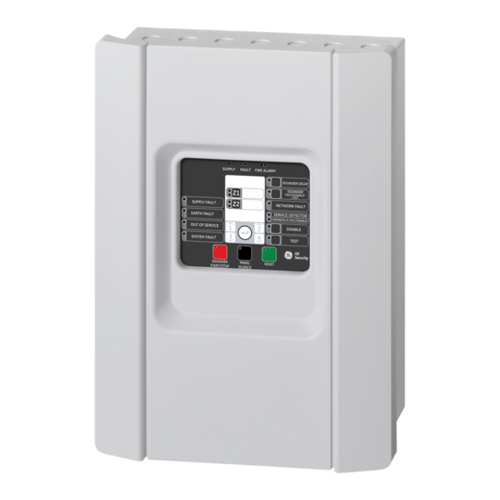
1X-E4 Series Quick Installation Guide
Figure 1: Zone and device connections
Overview
This document includes quick installation information for
your product. For detailed installation information, see
the installation manual.
Zones and zone devices
Connect zone wires and devices as shown in Figure 1.
Zone type and line resistance
Zones
Zone type
Odd
Automatic
Even
Manual
Detectors per zone
Dx700 series detectors
Other detectors
[1] Or as defined by local codes and standards
Each manual zone circuit can support up to 32 manual
call points with a resistance of 100 Ω to 680 Ω.
Resistance must be rated at 1 W minimum.
P/N 501-415403-4-20b • ISS 27JAN23
Line resistance
55 Ω max.
55 Ω max.
20 max.
32 max. [1]
Inputs and outputs
Each control panel has two inputs, marked INPUT1 and
INPUT2.
Input functions
INPUT1
Fire routing inhibit delay
INPUT2
Delays off
Input circuits should have a maximum resistance of
100 Ω (including any cable resistance).
Use outputs OUT1 to OUT4 to connect sounders.
Sounder outputs
Operating mode
Linked to fire detection zone
NEN 2575 with
OUT1 is activated by a fire alarm in zone 1
four evacuation
OUT2 is activated by a fire alarm in zone 2
areas
OUT3 is activated by a fire alarm in zone 3
OUT4 is activated by a fire alarm in zone 4
NEN 2575 with two
OUT1 and OUT2 are activated by a fire alarm in
evacuation areas
zone 1 or zone 2
OUT3 and OUT4 are activated by a fire alarm in
zone 3 or zone 4
1
Advertisement

Related Manuals for Aritech 1X-E4 Series


Summary of Contents for Aritech 1X-E4 Series
- Page 1 1X-E4 Series Quick Installation Guide Figure 1: Zone and device connections Overview Inputs and outputs This document includes quick installation information for Each control panel has two inputs, marked INPUT1 and your product. For detailed installation information, see INPUT2. the installation manual.
- Page 2 Enter Confirm a menu selection or a value selection entry. The configuration controls are also used to enter the access level password. The seven-segment display is visible when the control panel cover is removed. 1X-E4 Series Quick Installation Guide...
- Page 3 Default configured delays for all operating modes are shown below. Fire routing delay 1 minute Extended fire routing delay 3 minutes Contact information For contact information, see firesecurityproducts.com. Copyright © 2023 Carrier. All rights reserved. 1X-E4 Series Quick Installation Guide...
- Page 4 1X-E4 Series Quick Installation Guide...
Need help?
Do you have a question about the 1X-E4 Series and is the answer not in the manual?
Questions and answers