Aritech FP2000 Series User Instruction Manual
Analogue addressable fire panel
Hide thumbs
Also See for FP2000 Series:
- Installation instructions (2 pages) ,
- Reference manual (209 pages)

Related Manuals for Aritech FP2000 Series


Summary of Contents for Aritech FP2000 Series
- Page 1 FP2000 SERIES ANALOGUE ADDRESSABLE FIRE PANEL Version 3.1: May 1997 USER INSTRUCTION MANUAL...
-
Page 3: Table Of Contents
5. IN CASE OF PRE-WARNING 6. IN CASE OF FAULT 7. ROUTINE MAINTENANCE 7.1 DAILY 7.2 QUARTERLY 7.3 YEARLY APPENDIX A APPENDIX B FP2000 SERIES ANALOGUE ADDRESSABLE FIRE PANEL: USER INSTRUCTIONS Version 3.1 May 1997 Product Code: LKFP2403 Document No: 970528/205/M Page i... -
Page 5: Introduction
The FP2000 User Instruction Manual is intended as a guide to users (operators) of the Aritech FP2000 Series Analogue Addressable Fire Alarm Panel. Users are defined as those responsible for the routine day-to-day operation of the panel, including the handling of fire and fault conditions identified by the control panel. -
Page 6: Panel Operation
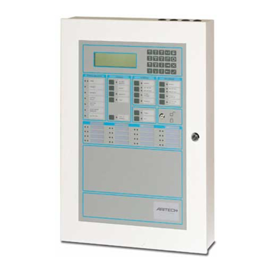
PANEL OPERATION A view of the front of a typical FP2000 Series Fire panel is shown in Figure 1 below. Figure 1: Fire Panel Front View FP2000 SERIES ANALOGUE ADDRESSABLE FIRE PANEL: USER INSTRUCTIONS Version 3.1 Page 2 May 1997... -
Page 7: Led Indications And Controls
In order to describe the operation of a FP2000 series fire panel, the front panel has been divided into two sections, these being: • LED indicators and controls • LCD and keypad LED INDICATIONS AND CONTROLS The LED indications and controls can further be broken down into: •... -
Page 8: General Indicators
• Any delays ON SUPPLY FAULT A yellow LED will illuminate for: • Mains failure • Battery disconnect or not charging FP2000 SERIES ANALOGUE ADDRESSABLE FIRE PANEL: USER INSTRUCTIONS Version 3.1 Page 4 May 1997 Product Code: LKFP2403 Document No: 970528/205/M... - Page 9 PROCESSOR RUNNING A flashing green LED indicates normal operation. SUPPLY ON A green LED indicates that the system is receiving 24V power. FP2000 SERIES ANALOGUE ADDRESSABLE FIRE PANEL: USER INSTRUCTIONS Version 3.1 May 1997 Product Code: LKFP2403 Document No: 970528/205/M...
-
Page 10: Controls
TEST (Keyswitch This push-button calls up the Test Menu. The yellow LED will illuminate if the panel is put into a test mode. FP2000 SERIES ANALOGUE ADDRESSABLE FIRE PANEL: USER INSTRUCTIONS Version 3.1 Page 6 May 1997... -
Page 11: Sounders
• Sounder circuit fuse failure SILENCE (Keyswitch A yellow LED indicates that the sounders have been silenced. Please refer to your Installer to the exact way of operation. FP2000 SERIES ANALOGUE ADDRESSABLE FIRE PANEL: USER INSTRUCTIONS Version 3.1 May 1997 Product Code: LKFP2403... -
Page 12: Fire Brigade
STOP FIRE BRIGADE (Keyswitch A yellow LED will indicate that the Fire Brigade signal has been deactivated. Please refer to your Installer to the exact way of operation. FP2000 SERIES ANALOGUE ADDRESSABLE FIRE PANEL: USER INSTRUCTIONS Version 3.1 Page 8... -
Page 13: Other
The yellow LED indicates that the key was pressed, meaning that the following command button to be pressed will be sent to all the relevant panels. FP2000 SERIES ANALOGUE ADDRESSABLE FIRE PANEL: USER INSTRUCTIONS Version 3.1 May 1997... -
Page 14: Zone Indicators
Figure 3: Zone Fire and Fault Indication LCD AND KEYPAD Figure 4: LCD and Keypad FP2000 SERIES ANALOGUE ADDRESSABLE FIRE PANEL: USER INSTRUCTIONS Version 3.1 Page 10 May 1997 Product Code: LKFP2403... - Page 15 Enter or confirm Move to the next field in the display Move to the previous field in the display Increment Decrement FP2000 SERIES ANALOGUE ADDRESSABLE FIRE PANEL: USER INSTRUCTIONS Version 3.1 May 1997 Product Code: LKFP2403 Document No: 970528/205/M Page 11...
-
Page 16: Normal Operation
3.5 All other Lamps OFF 3.6 The screen shows the System Status Menu as shown below: 3.7 The panel buzzer will sound for any abnormal condition that occurs with the fire panel. FP2000 SERIES ANALOGUE ADDRESSABLE FIRE PANEL: USER INSTRUCTIONS Version 3.1 Page 12... -
Page 17: In Case Of Fire
4.5.2 Press the SILENCE push-button. The yellow SILENCE lamp will illuminate. 4.5.3 To re-initiate evacuation press the SOUND push-button. The red SOUND lamp will illuminate. FP2000 SERIES ANALOGUE ADDRESSABLE FIRE PANEL: USER INSTRUCTIONS Version 3.1 May 1997 Product Code: LKFP2403... - Page 18 • A Manual Call Point Glass is broken - Repair or isolate • Detectors are contaminated with smoke - Clean detectors 4.6.3 Reset the fire panel as per 4.6.1. FP2000 SERIES ANALOGUE ADDRESSABLE FIRE PANEL: USER INSTRUCTIONS Version 3.1 Page 14...
-
Page 19: In Case Of Pre-Warning
• The condition is not under control - Refer to 5.3 above • Detectors are contaminated with smoke - Clean detectors 5.4.3 Reset the fire panel as per 4.6. FP2000 SERIES ANALOGUE ADDRESSABLE FIRE PANEL: USER INSTRUCTIONS Version 3.1 May 1997... -
Page 20: In Case Of Fault
The exact nature and location of the fault is displayed on the LCD screen as shown below: FP2000 SERIES ANALOGUE ADDRESSABLE FIRE PANEL: USER INSTRUCTIONS Version 3.1 Page 16 May 1997... -
Page 21: Routine Maintenance
ROUTINE MAINTENANCE In order to ensure the reliable operation of the FP2000 Series systems, they should be regularly tested and serviced. The following maintenance routine should be adopted: DAILY On a daily basis the user should check the following: 7.1.1 that the panel indicates normal operation, or if not, that any fault indicated is recorded in the logbook and reported to the maintenance personnel;... -
Page 22: Yearly
7.3.4 a visual inspection should be made to ensure that no structural or occupancy changes have affected the requirements for the siting of the manual call points, detectors and sounders. FP2000 SERIES ANALOGUE ADDRESSABLE FIRE PANEL: USER INSTRUCTIONS Version 3.1 Page 18... - Page 23 Loosen the two retaining screens as shown in Figure A.1 below and gently remove the printer. Figure A.1: Printer Retaining Screws FP2000 SERIES ANALOGUE ADDRESSABLE FIRE PANEL: USER INSTRUCTIONS Version 3.1 May 1997 Product Code: LKFP2403...
- Page 24 Remove the old printer cartridge. (Figure A.3) ! Note: First lift the left end of the printer cartridge, then the right. Figure A.3: Removal of Printer Cartridge FP2000 SERIES ANALOGUE ADDRESSABLE FIRE PANEL: USER INSTRUCTIONS Version 3.1 Page -A-2 May 1997...
- Page 25 If not, rotate the gear. Replace the front cover. Remount the printer to the door ensuring the retaining screws are firmly tightened. FP2000 SERIES ANALOGUE ADDRESSABLE FIRE PANEL: USER INSTRUCTIONS Version 3.1 May 1997...
- Page 27 Loosen the two retaining screws as shown in Figure B.1 below and gently remove the printer. Figure B.1: Printer Retaining Screws FP2000 SERIES ANALOGUE ADDRESSABLE FIRE PANEL: USER INSTRUCTIONS Version 3.1 May 1997 Product Code: LKFP2403...
- Page 28 If a paper roll has not been installed, remove the axle rod (Figure B.3), slide on the paper roll and replace the loaded axle rod in the slots (Figure B.4). Figure B.3: Removal of the Axle Rod FP2000 SERIES ANALOGUE ADDRESSABLE FIRE PANEL: USER INSTRUCTIONS Version 3.1 Page -B-2...
- Page 29 Replace the front cover. Remount the printer to the door ensuring the retaining screws are firmly tightened. FP2000 SERIES ANALOGUE ADDRESSABLE FIRE PANEL: USER INSTRUCTIONS Version 3.1 May 1997...
Need help?
Do you have a question about the FP2000 Series and is the answer not in the manual?
Questions and answers