Aritech 1X-F Series Operation Manual
Hide thumbs
Also See for 1X-F Series:
- Quick installation manual (4 pages) ,
- Quick operation manual (2 pages) ,
- Installation manual (113 pages)
Table of Contents
Advertisement
Advertisement
Table of Contents

Related Manuals for Aritech 1X-F Series


Summary of Contents for Aritech 1X-F Series
- Page 1 1X-F Series Operation Manual P/N 501-415003-2-50 • ISS 14JUN22...
- Page 2 Copyright © 2022 Carrier. All rights reserved. Trademarks and CleanMe and the 1X-F Series name and logo are trademarks of patents Carrier. Other trade names used in this document may be trademarks or registered trademarks of the manufacturers or vendors of the respective products.
-
Page 3: Table Of Contents
User interface for eight-zone control panels 4 Operator controls and indicators 5 Audible indicators 9 Summary of status indications 9 Control panel operation 13 User levels 13 Public user level operation 14 Operator user level operation 17 Maintenance 25 Regulatory information 26 1X-F Series Operation Manual... -
Page 4: Important Information
PRODUCTS, INCLUDING ANY “AUTHORIZED DEALER” OR “AUTHORIZED RESELLER”, IS PROPERLY TRAINED OR EXPERIENCED TO CORRECTLY INSTALL FIRE AND SECURITY RELATED PRODUCTS. For more information on warranty disclaimers and product safety information, please check https://firesecurityproducts.com/policy/product-warning/ or scan the QR code: 1X-F Series Operation Manual... -
Page 5: Advisory Messages
Note: Note messages advise you of the possible loss of time or effort. They describe how to avoid the loss. Notes are also used to point out important information that you should read. 1X-F Series Operation Manual... - Page 6 1X-F Series Operation Manual...
-
Page 7: Introduction
Introduction This is the operation manual for the 1X-F Series fire alarm control panels. Read these instructions and all related documentation entirely before operating this product. Product range The 1X-F Series includes the models shown below. Table 1: 1X-F Series models... -
Page 8: Sounder And Fire Routing Delays
Fire routing delay Extended fire routing delay EN 54-2 EN 54-2 Evacuation EN 54-2 Scandinavia BS 5839-1 NBN S 21-100 (evacuation sounders) (warning sounders) NEN 2535 Note: Fire routing is not available on any two-zone control panel. 1X-F Series Operation Manual... -
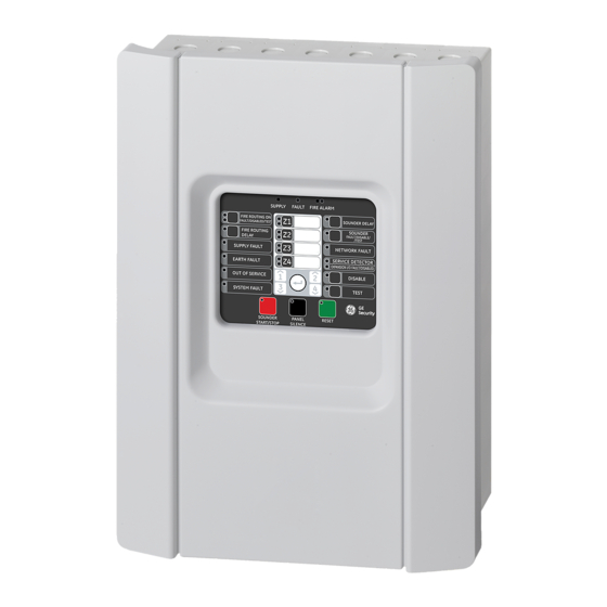
Page 9: Control Panel Overview
11. General Test button and LED Notes [1] Two-zone control panels do not include fire routing or warning sounders for NEN 2535. [2] Regional variants include changes to interface buttons and LEDs as shown in Table 4 on page 4. 1X-F Series Operation Manual... -
Page 10: User Interface For Eight-Zone Control Panels
Fire Protection Fault/Disable/Test Evacuation Sounder Delay Service Detector Fault Warning Fault/Disabled Service Detector Sounder Start/Stop Sounder Start/Stop Evacuation Start/Stop Fire Routing Delay Fire Routing Delay Warning Sounder Delay Fire Routing ON/ACK Fire Routing ON/ACK Warning Sounders Start/Stop 1X-F Series Operation Manual... -
Page 11: Operator Controls And Indicators
A flashing LED indicates a fault with the sounders — or — or evacuation sounders. A steady LED indicates Evacuation that the sounders or evacuation sounders are Fault/Disable/Test disabled or are being tested. button and LED for NBN S 21-100) 1X-F Series Operation Manual... - Page 12 LED protection and fault warning (NEN 2535 only), or expansion I/O boards (when pressed with the corresponding button). A steady General Disable LED and the corresponding zone, sounders, or fire routing Fault/Disable/Test LED indicates a disablement. 1X-F Series Operation Manual...
- Page 13 Depending on the size of your installation, the processing of commands to start or stop sounders may take a few seconds to travel through the system. For example, the LED may be steady before the sounders are audible. 1X-F Series Operation Manual...
- Page 14 LED A flashing LED indicates a fault. A steady LED — or — indicates that the function is disabled or is being tested. Warning Fault/Disable/Test button and LED for NBN S 21-100 1X-F Series Operation Manual...
-
Page 15: Audible Indicators
(counting). Flashing fast when an extended fire routing delay is active (counting). • Fire Routing ON/ACKd LED: Flashing when fire routing is activated. On steady when the fire routing signal has been acknowledged by the remote monitoring equipment. • Control panel buzzer: Sounding continuous. 1X-F Series Operation Manual... - Page 16 Corresponding zone, function, or device LED: Flashing yellow. • Control panel buzzer: Sounding intermittent. Mains power fault and mains fuse fault indication: • General Fault LED: Flashing. • Supply Fault LED: On steady. • Control panel buzzer: Sounding intermittent. 1X-F Series Operation Manual...
- Page 17 • I/O LED: On steady yellow. • Control panel buzzer: Off. Disabled fire protection is indicated as follows: • General Disable LED: On steady. • Fire Protection LED: On steady yellow. • Control panel buzzer: Off. 1X-F Series Operation Manual...
- Page 18 When power is re-established the control panel returns to its former status. Note: When the control panel indicates out of service, your fire alarm system is partly inactive and your site is not properly protected. Contact your installation or maintenance contractor immediately to investigate the problem. 1X-F Series Operation Manual...
-
Page 19: Control Panel Operation
The control panel is available with an access key option. The key switch is located on the panel cover. With this option, either the key or the password can be used to enter the operator user level. 1X-F Series Operation Manual... -
Page 20: Public User Level Operation
A configured delay is active (sounders are activated when the configured delay elapses or when the delay is cancelled). A fire alarm activated by a manual call point overrides any configured delay and activates sounders immediately. 1X-F Series Operation Manual... - Page 21 12 seconds). When the test is completed the control panel returns to its former state. Note: Devices connected to the control panel fault relay will also be activated for the duration of this test. 1X-F Series Operation Manual...
- Page 22 8 to disappear, indicating that the control panel has zone 8 disabled. At this point, you will know the alarm is from zone 8 of panel 2. You can confirm this by pushing Enter for 3 seconds in panel 2. In this case, the yellow LED indication disappears. 1X-F Series Operation Manual...
-
Page 23: Operator User Level Operation
Investigate all alarms and system faults before resetting the control panel. To reset the control panel and clear all current system events, press the Reset button. System events that have not been resolved continue to be highlighted when the reset process ends. 1X-F Series Operation Manual... - Page 24 Contact your installation or maintenance contractor to confirm all configuration details for your site. Note: Sounders are always restarted when the control panel detects a manual alarm and it was in automatic alarm state. 1X-F Series Operation Manual...
- Page 25 (This delay option is also available for EN 54-2 and NEN 2535 operating modes if configured during installation. Contact your fire system installation or maintenance contractor to confirm your configuration details.) 1X-F Series Operation Manual...
- Page 26 Note: The control panel buzzer and sounders may be configured not to sound when an alarm is activated in a zone being tested. Contact your fire system installation or maintenance contractor to confirm your configuration details. 1X-F Series Operation Manual...
- Page 27 If it is the only zone in alarm, no fire alarm or fault is indicated for the disabled zone and any linked fire outputs are stopped. If one or more zones are in alarm when the zone is enabled, the zone enters into alarm and re-activates the stopped fire outputs. 1X-F Series Operation Manual...
- Page 28 To enable the sounders, press the General Disable button, and then press the Sounder Fault/Disable/Test button (or Evacuation Fault/Disable/Test button for NBN S 21-100) again. Note: Disabled sounders (or evacuation for NBN S 21-100) do not indicate a fault or operate if there is a fire alarm. 1X-F Series Operation Manual...
- Page 29 Fire Routing ON/ACK button (or Warning Start/Stop button for NBN S 21-100) again. Note: Disabled fire routing (or warning for NBN S 21-100) does not operate or indicate a fault if there is a fire alarm. 1X-F Series Operation Manual...
- Page 30 To enable a disabled option, press the General Disable button for more than 3 seconds, press the 1 and 3 buttons to select the option to be enabled, and then press Enter. Note: Disabled expansion boards will not operate or indicate a fault if there is a fire alarm. 1X-F Series Operation Manual...
-
Page 31: Maintenance
Keep the outside and inside of the control panel clean. Carry out periodic cleaning using a damp cloth for the outside. Do not use products containing solvents to clean the unit. Do not clean the inside of the cabinet with liquid products. 1X-F Series Operation Manual... -
Page 32: Regulatory Information
European standards for electrical safety and electromagnetic compatibility These control panels have been designed in accordance with the following European standards for electrical safety and electromagnetic compatibility: • EN 62368-1 • EN 50130-4 • EN 61000-6-3 • EN 61000-3-2 • EN 61000-3-3 1X-F Series Operation Manual... - Page 33 1X-F2, 1X-F2-SC 360-3100-0599 1X-F4, 1X-F4-NL, 1X-F4-SC 360-3100-0699 1X-F8, 1X-F8-NL, 1X-F8-SC 360-3100-0899 Product identification See model number on product identification label Intended use See the product Declaration of Performance Declared performance See the product Declaration of Performance 1X-F Series Operation Manual...
Need help?
Do you have a question about the 1X-F Series and is the answer not in the manual?
Questions and answers