
Subscribe to Our Youtube Channel
Related Manuals for Wilson Electronics WilsonPro ENTERPRISE A8000


Summary of Contents for Wilson Electronics WilsonPro ENTERPRISE A8000
- Page 1 A Wilson Electronics Brand ENTERPRISE In-Building Cell Signal Amplifier with Multi- Tower Targeting (MTT) Technology Installation Guide...
- Page 2 In-Building Cellular Connectivity. Amplified Commercial-grade solutions for improving cell signal coverage.
- Page 3 Index Package Contents About The Enterprise A8000 Additional Features Installation Diagram Menu System WilsonPro Cloud Local Amplifier Configuration Utility Safety Guidelines Specifications Warranty...
-
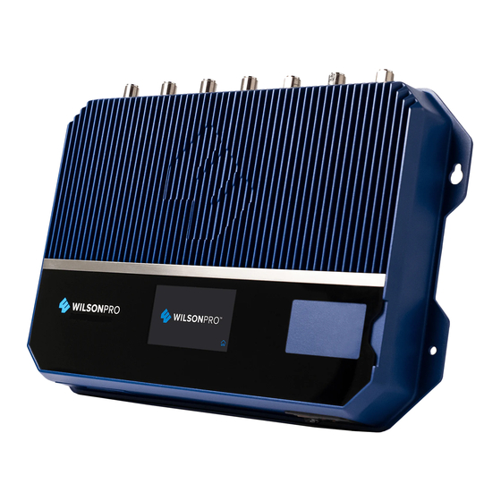
Page 4: Package Contents
Package Contents Enterprise A800 Type G Power Cable & Enterprise A8000 Amplifier E/F Power Cable ENTERPRISE A8000 IN-BUILDING CELL SIGNAL AMPLIFIER... - Page 5 Enterprise A8000 In-Building Cell Signal Amplifier System Covers E-UTRA Cell Bands 1, 3, 7, & 8. Frequency-specific “split mode” option, facilitating separate outdoor antennas for different bands, resulting in improved indoor coverage. Remote system monitoring. Connects to WilsonPro Cloud service via Ethernet interface.
- Page 6 The Enterprise A8000 cell signal amplifier systems provide significantly enhanced 4G LTE and 5G coverage inside buildings where cell signals may not otherwise penetrate. Installation of an Enterprise A8000 cell signal amplifier system results in fewer dropped calls, improved voice quality, uninterrupted texts, and faster data speeds—along with better audio and video streaming.
-
Page 7: Additional Features
Additional Features Extended Dynamic Range (XDR) for continuous connectivity: XDR allows the Enterprise A8000 system to make automatic, real-time adjustments so it never shuts down due to a strong outside signal. Remote Connectivity and Monitoring: Unit can be remotely monitored and cell bands turned on and off (internet connection to unit is required). -
Page 8: Installation Diagram
Installation Diagram The Enterprise A8000 supports up to four inside antennas and are capable of operating in traditional Common Mode, in which all amplifier cell bands use the same outdoor antenna, or Split Mode, in which cell bands use separate outdoor antennas. Common Common mode can be used for an installation in which cell towers for different bands are located in the same direction . -
Page 9: Split Mode
(INSTALLATION DIAGRAM cont.) Split Mode Split mode is advantageous for an installation in which cell towers for different bands are located in different directions. Outdoor directional antennas can be pointed to provide maximum cell coverage for each band. 900 MHz Cell Tower Outside Antennas 1700-2200 MHz... -
Page 10: Mounting Specifications
Mounting Specifications Wall Mounting Installation (for most situations) Fasten a sheet of 4’x4’x ¾” plywood utilizing 4x 3/16” x 3” toggle bolts with a minimum tensile rating of 35 lbs, then use 4x #12 x ¾” Pan Head Wood Screws to secure the booster to the plywood. -
Page 11: Post-Install Setup
Post-Install Setup The Enterprise A8000 systems are designed with advanced internal programming, which allows it to automatically adjust for a variety of conditions, including the added functionality, alerts, and troubleshooting of an enhanced cloud management and monitoring solution. Once the AC power cable and antenna cables are connected, scan the QR code on the Quick Registration Card to add the amplifier to your WilsonPro Cloud account. -
Page 12: Menu System
Menu System The Enterprise A8000 takes about 8 seconds to boot up. Once boot up is complete, the home screen will appear, showing the amplification and status of each port and band. Home Screen Start Up Screen Band Menu Color Description Green indicates that a band is operating correctly with maximum allowable gain. - Page 13 (MENU SYSTEM cont.) Red indicates a band has been shut down because of a severe oscillation condition or repeated oscillation. Reposition antennas (increase separation between indoor and outdoor antennas, and point in opposite directions) and then reboot (turn the unit off &...
-
Page 14: Settings Screen
Settings Screen Tap ‘Settings Icon’ in the lower right corner to view the Settings Screen. There are 4 Settings Screens represented by “tabs”. Tap the tab heading to view each Settings Screen. General settings below. Note: Bands and Ports are disabled or enabled from the Local Amplifier Configuration Utility only. - Page 15 (MENU SYSTEM - SETTINGS SCREEN cont.) Ethernet Settings Tab Cloud Communication Settings Tab IN-BUILDING CELL SIGNAL AMPLIFIER ENTERPRISE A8000...
- Page 16 (MENU SYSTEM - SETTINGS SCREEN cont.) Cloud Communication Settings Tab Note: The Reset Local Comm button resets the login credentials for the Local Amplifier Configuration Utility to factory defaults. Antenna Settings Tab Common Mode is configured from the Local Amplifier Configuration Utility and should be set when using a single Outside Antenna.
- Page 17 (MENU SYSTEM - SETTINGS SCREEN cont.) Split-Mode Configuration Split Mode is configured from the Local Amplifier Configuration Utility and should be set when using separate Outside Antennas for Band 1, Band 3, Band 7, and Band 8. To go back to the Home Screen, tap on the Home Icon (in the lower right corner). IN-BUILDING CELL SIGNAL AMPLIFIER ENTERPRISE A8000...
-
Page 18: Band-Status Screens
Band-Status Screens To view specific band information (such as the strength of the received uplink & down- link signal, outside signal strength, and amplifier gain status) tap the desired band on the home screen. Oscillation Example ENTERPRISE A8000 IN-BUILDING CELL SIGNAL AMPLIFIER... - Page 19 (MENU SYSTEM - BAND-SATUS SCREENS cont.) Shutdown Example IN-BUILDING CELL SIGNAL AMPLIFIER ENTERPRISE A8000...
- Page 20 Connectivity Status Screens The two icons in the upper right provide status related to the Ethernet connection and USB device (if inserted). Ethernet-Status Icon ENTERPRISE A8000 IN-BUILDING CELL SIGNAL AMPLIFIER...
-
Page 21: Wilsonpro Cloud
WilsonPro Cloud The cloud-based platform for remote monitoring & control of cellular signal amplifiers Enterprise A8000 connects to WilsonPro Cloud via the internet, through a traditional RJ-45 “hardwired” Ethernet connection. Logging into the WilsonPro Cloud via Ethernet If you don’t already have a WilsonPro Cloud™ account at cloud.wilsonpro.com, call 011 749 3085, Monday-Friday 8am-5pm so that your account can be created. - Page 22 (WILSONPRO CLOUD cont.) Customer Dashboard You can quickly check the status of all of your amplifiers from the Dashboard summary screen. The Total Alert Status represents the number of alert indications, for all amplifiers assigned to your account, that have not been acknowledged. After an alert is acknowledged, it is no longer included in this chart.
- Page 23 (WILSONPRO CLOUD – ADDING A CUSTOMER cont.) Enter information for Customer (business/organization utilizing the Enterprise A8000 product), Primary Contact (notification recipient), and select a Monitor. After clicking on SUBMIT the new customer will appear on the dashboard page below the alert and status summary with a default location. Customer Information: This section is pertaining to the business/organization utilizing Enterprise A8000 amplifier(s) at...
- Page 24 (WILSONPRO CLOUD – ADDING A CUSTOMER cont.) If a Monitor has not been created, click on NEW MONITOR at the top of the webpage. Installer/Integrator can assign Monitors to track the performance of the amplifier(s). A Monitor can be made Administrator, who can see all information within the account and create additional Monitors.
- Page 25 (WILSONPRO CLOUD cont.) Creating an Additional Customer Location To create an additional customer location click VIEW. Then click ADD NEW LOCATION. IN-BUILDING CELL SIGNAL AMPLIFIER ENTERPRISE A8000...
- Page 26 (WILSONPRO CLOUD – ADDING A CUSTOMER LOCATION cont.) Enter information and click SUBMIT. NOTE: Customer Information and Primary Contact fields are required, these must be populated before submitting page. ENTERPRISE A8000 IN-BUILDING CELL SIGNAL AMPLIFIER...
-
Page 27: Adding An Amplifier
(WILSONPRO CLOUD cont.) Adding an Amplifier On the dashboard page, find the customer location you would like to add the amplifier and click VIEW. Then click ADD AMPLIFIER. Add an amplifier name. An example: Hotel Lobby etc. IN-BUILDING CELL SIGNAL AMPLIFIER ENTERPRISE A8000... - Page 28 (WILSONPRO CLOUD – ADDING A AMPLIFIER cont.) Click SCAN AMPLIFIER QR CODE located on Quick Setup Card (which is in the plastic sleeve on the amplifier). The serial number and MAC address will autopopulate after scanning QR code. Click LOOK UP SERIAL NUMBERS. NOTE: The serial number and MAC address fields can be populated manually.
- Page 29 (WILSONPRO CLOUD cont.) Amplifier Metrics Now that the amplifier(s) have been added to the location, click VIEW to view details about the amplifier. Click VIEW, in the amplifier list. IN-BUILDING CELL SIGNAL AMPLIFIER ENTERPRISE A8000...
- Page 30 (WILSONPRO CLOUD – AMPLIFIER METRICS cont.) The Band Details table above shows per-Band performance metrics. In addition, Bands can be disabled and re-enabled, as well as viewing the Band History. ENTERPRISE A8000 IN-BUILDING CELL SIGNAL AMPLIFIER...
- Page 31 (WILSONPRO CLOUD – AMPLIFIER METRICS cont.) The Band History screen provides performance and signal level histories. IN-BUILDING CELL SIGNAL AMPLIFIER ENTERPRISE A8000...
-
Page 32: Alerts & Notifications
(WILSONPRO CLOUD cont.) Alerts & Notifications Alerts are displayed on the Location Details screen for all amplifiers for that location. Alerts are also displayed on the Amplifier Details screen for that particular amplifier. To acknowledge and remove the alert from the lists, choose the alert and click SUBMIT ACKNOWLEDGEMENT. - Page 33 (WILSONPRO CLOUD – ALERTS & NOTIFICATIONS cont.) To view past alerts that have been removed from the list, click VIEW ALERT HISTORY. To set which amplifier conditions will result in an alert, click CONFIGURE ALERTS (this can be done from the Amplifier Details screen as well). IN-BUILDING CELL SIGNAL AMPLIFIER ENTERPRISE A8000...
- Page 34 (WILSONPRO CLOUD – ALERTS & NOTIFICATIONS cont.) Select individual, multiple, or all conditions to change the priority level of all selected alerts, click UPDATE after modifying the conditions. These alerts (which can be set as notifications) and then will be pushed to SMS (text) and email. To configure Alert notifications click CONFIGURE NOTIFICATIONS.
- Page 35 (WILSONPRO CLOUD – ALERTS & NOTIFICATIONS cont.) You can configure Alert notifications for this Location to be sent to Recipients. These Recipients can either be Monitors registered in the system, or ‘other’ Recipients identified by email or phone. To add or delete Recipients, click on the .
- Page 36 Local Amplifier Configuration Utility If you need to view or modify the local amplifier configuration settings, this utility was created to help you. With this utility, you can change Cloud Communication Preferences and Ethernet settings, as well as enable/disable bands and ports. It can also be used to view live band details and the static information such as firmware version.
- Page 37 (LOCAL AMPLIFIER CONFIGURATION UTILITY cont.) Once the network icon is yellow, type wilsonproconfig into the web browser. A login will be displayed, type the following: Username: admin – Password: admin (factory default). On the Local Amplifier Configuration Utility page you can select AMPLIFIER, COMMUNICATIONS and SYSTEM to set configurations.
- Page 38 (LOCAL AMPLIFIER CONFIGURATION UTILITY cont.) Bands can be turned ON/OFF, you can configure Inside Antenna Settings (ON/OFF) and you can update the Outside Antenna Configuration (COMMON/SPLIT MODE). Note: Once you make changes to either the Band Enable or Communication Settings, you must wait at least 30 seconds before power cycling the unit or the new settings will not be stored.
- Page 39 (LOCAL AMPLIFIER CONFIGURATION UTILITY cont.) Click on then COMMUNICATIONS, Communications Preferences and Ethernet changes can be made here. Click on then SYSTEM, set password for local amplifier (this password is unrelated to WilsonPro Cloud Service), reboot amplifier and restore system to factory default. IN-BUILDING CELL SIGNAL AMPLIFIER ENTERPRISE A8000...
- Page 40 (LOCAL AMPLIFIER CONFIGURATION UTILITY cont.) Click on then AMPLIFIER, view overall status of amplifier, LTE connection, Ethernet conection, USB connection and power levels for each band. ENTERPRISE A8000 IN-BUILDING CELL SIGNAL AMPLIFIER...
- Page 41 (LOCAL AMPLIFIER CONFIGURATION UTILITY cont.) Click on then SYSTEM, view overall system details. Click on to use the ANTENNA TUNER to assist with orienting the antenna. Click CAPTURE CURRENT VALUES and enter an optional label for antenna position to record measurements. These steps can be repeated as many times as you like. IN-BUILDING CELL SIGNAL AMPLIFIER ENTERPRISE A8000...
- Page 42 (LOCAL AMPLIFIER CONFIGURATION UTILITY cont.) Troubleshooting Local Amplifier Configuration Utility Using the LCD screen on the amplifier to find the IP Address You can use the LCD screen on the amplifier to find the IP Address of the Ethernet connection after the laptop is connected. This IP Address can be used instead of “wilsonproconfig”.
-
Page 43: Safety Guidelines
To uphold compliance with network protection standards, all active cellular devices must maintain at least 6 feet of separation distance from Panel and Dome antennas. Use only the power supply cord provided in this package. Use of a non-Wilson Electronics product may damage your equipment. -
Page 44: Specifications
Specifications Model Number A8000 Connectors N-Connectors Antenna Impedance 50 Ohms 880-915 MHz, 925-960 MHz, 1710-1785 MHz, 1805-1880 MHz,1920-1980 MHz, 2110-2170 MHz, 2500- Frequency 2570 MHz, 2620-2690 MHz Max Gain dBm Power output for single cell Band 1 Band 3 Band 7 Band 8 phone (Uplink) dBm Power output for single cell... -
Page 45: Warranty
MARKETING APPROVAL: Installer and end customer hereby grants to Wilson Electronics the express right to use installers or end customers company logo in marketing, sales, financial, and public relations materials and other communications solely to identify Customer as a Wilson Electronics customer. - Page 46 A Wilson Electronics Brand www. Copyright © 2020 Wilson Electronics. All rights reserved. Wilson Electronics products covered by U.S. patent(s) and pending application(s) For patents go to: weboost.com/us/patents NOT AFFILIATED WITH WILSON ANTENNA...
Need help?
Do you have a question about the WilsonPro ENTERPRISE A8000 and is the answer not in the manual?
Questions and answers