
Related Manuals for Wilson Electronics WILSONPRO ENTERPRISE 4330


Summary of Contents for Wilson Electronics WILSONPRO ENTERPRISE 4330
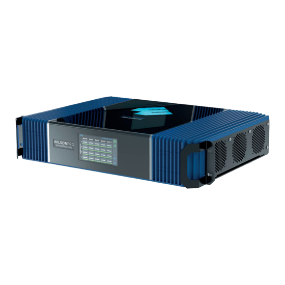
- Page 1 A Wilson Electronics Brand ENTERPRISE 4330 In-Building Cell Signal Amplifier with Channelization Technology Installation Guide wilsonpro.com 866.294.1660...
- Page 2 Index Package Contents About The Enterprise 4330 Features Installation Diagram Menu System WilsonPro Cloud Local Amplifier Configuration Utility Troubleshooting Local Amplifier Configuration Utility Safety Guidelines Specifications Warranty...
-
Page 3: Package Contents
Package Contents Enterprise 4330 SKU 462075 Enterprise 4330 Wide Band Dome Antennas 30 m. (100 ft.) Amplifier Directional Antenna (qty. 4) Wilson400 Cable (qty. 5) (460075) (314411) (304412) (952300) 60 cm. (2 ft.) 50 Ohm Lightning Wilson400 Cable Surge Protector (952302) (859902) Enterprise 4330... - Page 4 Enterprise 4330 In-Building Cell Signal Amplifier with Channelization Technology Specific sub-blocks within a band can be selected (filtered) for amplification, if desired. Filters may be configured either through the LACU or via WilsonPro Cloud remote internet management. Frequency-specific “split mode” option, facilitating separate outdoor antennas for different bands, resulting in improved indoor coverage.
- Page 5 Ethernet port. The wireless LTE connection is included in the annual WilsonPro Cloud subscription, so no additional Internet connection is required. The Enterprise 4330 cell signal amplifier system now incorporates Wilson Electronics’ channelization technology. Although traditional “wideband mode” is enabled by default, specific sub-blocks within a cell band can be selected for amplification, if desired.
- Page 6 Features Channelization Technology: Specific sub-blocks within a band can be selected (filtered) for amplification, if desired. Filters may be configured either through the local amplifier configuration utility (LACU) or via WilsonPro Cloud remote internet management. Cellular Network Scanning: Provides RSRP (Reference Signal Received Power) and RSRQ (Reference Signal Received Quality) for major cellular carriers in the U.S.
-
Page 7: Installation Diagram
Installation Diagram The Enterprise 4330 supports up to four inside antennas and are capable of operating in traditional Common Mode, in which all amplifier cell bands use the same outdoor antenna, or Split Mode, in which cell bands use separate outdoor antennas. Common Mode Common mode can be used for an installation in which cell towers for different bands are located in the same direction. -
Page 8: Split Mode
INSTALLATION DIAGRAM cont.) Split Mode Split mode is advantageous for an installation in which cell towers for different bands are located in different directions. Outdoor directional antennas can be pointed to provide maximum cell coverage for each band. 800 MHz Cell Tower Outside Antennas 1700-2200 MHz... -
Page 9: Mounting Specifications
Mounting Specifications Wall Mounting Installation (for most situations) Fasten a sheet of 4’x4’x ¾” plywood utilizing 4 x 3/16”x 3” toggle bolts with a minimum tensile rating of 35 lbs, then use 4x #12 x¾” Pan Head Wood Screws or ½” x 2” lag screws to secure the booster to the plywood. -
Page 10: Rack Mounting Installation
MOUNTING SPECIFICATIONS cont.) Rack Mounting Installation Mount to EIA Standard 19” Server Rack (compliant with EIA-310-D) with 4 standard #10 or #12 cage Screws and Nuts. Please reference the below diagram: Standard #10 or #12 Cage Screws & Nuts EIA Standard 19” Server Rack WARNING: Proper installation environment to reduce risks related to the environment, the unit must be installed indoors only. -
Page 11: Post-Install Setup
Post-Install Setup The Enterprise 4330 systems are designed with advanced internal programming, which allows it to automatically adjust for a variety of conditions, including the added functionality, alerts, and troubleshooting of an enhanced cloud management and monitoring solution. Once the AC power cable and antenna cables are connected, see WilsonPro Cloud section to add the amplifier to your account. -
Page 12: Menu System
Menu System The Enterprise 4330 takes about 3 minutes to boot up. Once boot up is complete, the home screen will appear, showing the amplification and status of each port and band. Home Screen Start Up Screen Band Menu Color Description Green indicates that a band is operating correctly with maximum allowable gain. - Page 13 (MENU SYSTEM cont.) Red indicates a band has been shut down because of a severe oscillation condition or repeated oscillation. Reposition antennas (increase separation between indoor and outdoor antennas, and point in opposite directions) and then reboot (turn the unit off &...
-
Page 14: Settings Screen
Settings Screen Tap ‘Settings Icon’ in the lower right corner to view the Settings Screen. There are 5 Settings Screens represented by “tabs”. Tap the tab heading to view each Settings Screen. General settings below. Note: Bands and Ports are disabled or enabled from the Cloud or Local Amplifier Configuration Utility only. - Page 15 (MENU SYSTEM - SETTINGS SCREEN cont.) Ethernet Settings Tab Modem Settings Tab ENTERPRISE 4330 IN-BUILDING CELL SIGNAL AMPLIFIER...
- Page 16 (MENU SYSTEM - SETTINGS SCREEN cont.) Cloud Communication Settings Tab Note: The Reset Local Comm button is used in case the user has configured the amplifier such that the Local Amplifier Configuration Utility (LACU) is not accessible, e.g., if the communication preferences are set to “LTE Only” or the LACU password needs to be reset.
- Page 17 (MENU SYSTEM - SETTINGS SCREEN cont.) Split-Mode Configuration Split Mode is configured from the Local Amplifier Configuration Utility and should be set when using separate Outside Antennas for Band 4/25, Band 5, and Band 12/13. To go back to the Home Screen, tap on the Home Icon (in the lower right corner). ENTERPRISE 4330 IN-BUILDING CELL SIGNAL AMPLIFIER...
- Page 18 Band-Status Screens To view specific band information (such as the strength of the received uplink & down- link signal, outside signal strength, and amplifier gain status) tap the desired band on the home screen. Oscillation Example Note: If the reduced gain due to oscillation is greater than or equal to 60dB, the condition will be displayed as Green and no action is necessary.
- Page 19 (MENU SYSTEM - BAND-STATUS SCREENS cont.) Shutdown Example ENTERPRISE 4330 IN-BUILDING CELL SIGNAL AMPLIFIER...
- Page 20 Connectivity Status Screens The two icons in the upper right provide status related to the Ethernet connection and Cloud connection. Ethernet-Status Icon Cloud-Status Icon IN-BUILDING CELL SIGNAL AMPLIFIER ENTERPRISE 4330...
- Page 21 (MENU SYSTEM - CONNECTIVITY STATUS SCREENS cont.) The Cellular Network Scan screen provides RSRP (Reference Signal Received Power) and RSRQ (Reference Signal Received Quality) for major cellular carriers in U.S. and Canada, measured at the indoor antenna ports (after the signal has been amplified). Band, frequency, bandwidth and cell I.D.
-
Page 22: Wilsonpro Cloud
WilsonPro Cloud The cloud-based platform for remote monitoring & control of cellular signal amplifiers Enterprise 4330 connects to WilsonPro Cloud via the internet, through a standard RJ-45 “hardwired” Ethernet connection or via LTE connection through the outside Comm antenna. The default setting is “Ethernet Preferred” (gives priority to Ethernet, but will switch to LTE if Ethernet is not connected). - Page 23 (WILSONPRO CLOUD cont.) Customer Dashboard You can quickly check the status of all of your amplifiers from the Dashboard summary screen. The Top Alert field represents the highest priority alert reported by each amplifier assigned to your account, that has not been acknowledged. After all alerts have been acknowledged, they are no longer shown in this chart.
- Page 24 (WILSONPRO CLOUD – ADDING A CUSTOMER cont.) Enter information for Customer (business/organization). After clicking on Save the new customer will appear on the dashboard page. To Add Location, click on the button and click Add Location. IN-BUILDING CELL SIGNAL AMPLIFIER ENTERPRISE 4330...
- Page 25 (WILSONPRO CLOUD cont.) Adding Customer Location Enter Location Name and Primary Contact (notification recipient) information and click save. NOTE: Fields with red asterisks are required. ENTERPRISE 4330 IN-BUILDING CELL SIGNAL AMPLIFIER...
-
Page 26: Adding An Amplifier
(WILSONPRO CLOUD cont.) Adding an Amplifier To add a amplifier, click on the button on desired location and click View to open location summary page. Click on Add Amplifier and enter the amplifier serial number, MAC address and amplifier name. An example: 1st Floor Lobby. IN-BUILDING CELL SIGNAL AMPLIFIER ENTERPRISE 4330... - Page 27 (WILSONPRO CLOUD cont.) Adding a Monitor If a Monitor has not been created, click on Add Monitor. Installer/Integrator can assign monitors to track the performance of the amplifier(s). Alert priorities can be set to low, medium or high. ENTERPRISE 4330 IN-BUILDING CELL SIGNAL AMPLIFIER...
- Page 28 (WILSONPRO CLOUD cont.) Amplifier Configuration & Metrics Now that the amplifier(s) have been added to the location, click button and click VIEW to view details about the amplifier. IN-BUILDING CELL SIGNAL AMPLIFIER ENTERPRISE 4330...
- Page 29 (WILSONPRO CLOUD – AMPLIFIER METRICS cont.) The Band Details table shows per-band performance metrics. In addition, bands can be disabled and re-enabled, as well as viewing the band history. WARNING: Disabling bands could disconnect the LTE connection and prevent communication with the cloud. ENTERPRISE 4330 IN-BUILDING CELL SIGNAL AMPLIFIER...
- Page 30 (WILSONPRO CLOUD – AMPLIFIER METRICS cont.) In the Band Details section, band history can be viewed by clicking button, by each band, and then click View History. The Band can be disabled as well. The Band History screen provides performance and signal level histories. IN-BUILDING CELL SIGNAL AMPLIFIER ENTERPRISE 4330...
- Page 31 (WILSONPRO CLOUD – AMPLIFIER METRICS cont.) If, within a band, specific carriers or sub-blocks are desired for amplification, click the configure button at the top of the Band Channelization section. If Custom is selected for a particular band, sub-blocks are manually selected. Note that any number of sub-blocks may be selected;...
- Page 32 (WILSONPRO CLOUD – AMPLIFIER METRICS cont.) In the Inside Antenna Port Details section port(s) can be disabled by clicking the button and click Disable. Active and acknowledged alerts can be viewed in the Alert section. To view alert history click and then click View History.
- Page 33 (WILSONPRO CLOUD – AMPLIFIER METRICS cont.) The outside antenna can be configured into Split Mode in Antenna Configuration section, if needed. The inside antenna can be configured into Zinwave Server Mode in Antenna Configuration section, as well. ENTERPRISE 4330 IN-BUILDING CELL SIGNAL AMPLIFIER...
- Page 34 (WILSONPRO CLOUD cont.) Cellular Network Scanning The Cellular Network Scan feature with provides RSRP (Reference Signal Received Power) and RSRQ (Reference Signal Received Quality) for major U.S. and Canadian Carrier cellular signals found by the amplifier, measured at the indoor antenna ports (after the signal has been amplified).
- Page 35 (WILSONPRO CLOUD – CELLULAR NETWORK SCANNING cont.) eNodeB (eNB) is a unique numeric value that represents the cellular radio base station associated with a scanned signal result. Click on the eNB value to be redirected to a new browser window that opens a 3rd-party website that plots this eNB value on a map.
- Page 36 Local Amplifier Configuration Utility If you want to view or modify the amplifier configuration settings directly on the amplifier, this utility was created to help you. With this utility, you can change Communication Preferences and Ethernet settings, as well as Enable/Disable bands and ports.
- Page 37 (LOCAL AMPLIFIER CONFIGURATION UTILITY cont.) Once the network icon is yellow or green, type the IP Address of the amplifier that is shown on the LCD screen under Settings / Ethernet that is assigned when the Ethernet icon is yellow or green. Alternately, type wilsonproconfig into the web browser.
- Page 38 (LOCAL AMPLIFIER CONFIGURATION UTILITY cont.) Bands can be ENABLED/DISABLED and they can be configured to support specific channels/carriers. Inside Antennas can be also be ENABLED/DISABLED and they can be configured to support interworking with a fiber transmission unit if desired. Outside Antennas can be configured to support a frequency-specific Split Mode option that supports separate antennas for different bands, or a Common Mode where only one outside antenna will be used for all bands.
- Page 39 (LOCAL AMPLIFIER CONFIGURATION UTILITY cont.) The inside antennas can be ENABLED/DISABLED and, if desired, configured for Zinwave Server Mode for integration with a Zinwave fiber transmission unit. NOTE: Antenna 4 cannot be disabled. It is required for LTE modem communication. The default outside antenna configuration is for an antenna to be connected to the Antenna 2 port, with Antenna 1 and Antenna 3 ports not being used (COMMON MODE).
- Page 40 (LOCAL AMPLIFIER CONFIGURATION UTILITY cont.) Click on then SYSTEM to set password for local amplifier (this password is unrelated to WilsonPro Cloud Service), reboot amplifier and restore system to factory default. NOTE: Any settings change made to the amplifier from the Local Amplifier Configuration Utility will take up to 30 seconds to reliably save to memory.
- Page 41 (LOCAL AMPLIFIER CONFIGURATION UTILITY cont.) Click on then AMPLIFIER, view overall status of amplifier, WilsonPro Cloud, LTE connection, Ethernet conection, USB connection and power levels for each band per inside antenna/server port. Click on then SYSTEM, view overall system details. ENTERPRISE 4330 IN-BUILDING CELL SIGNAL AMPLIFIER...
- Page 42 (LOCAL AMPLIFIER CONFIGURATION UTILITY cont.) Click on to use the Cellular Network Scan feature which provides RSRP (Reference Signal Received Power) and RSRQ (Reference Signal Received Quality) for major U.S. and Canadian Carrier cellular signals found by the amplifier, measured at the indoor antenna ports (after the signal has been amplified).
- Page 43 (LOCAL AMPLIFIER CONFIGURATION UTILITY cont.) Troubleshooting Local Amplifier Configuration Utility Using the LCD screen on the amplifier to find the IP Address You can use the LCD screen on the amplifier to find the IP Address of the Ethernet connection after the laptop is connected. This IP Address can be used instead of wilsonproconfig.
-
Page 44: Safety Guidelines
1.8 m (6 feet) of separation distance from Panel and Dome antennas. Use only the power supply provided in this package. Use of a non-Wilson Electronics product may damage your equipment. The Signal Amplifier unit is designed for use in an indoor, temperature-controlled environment (operating temperature ranges from 0°C to 35°C (32°F to 95°F). -
Page 45: Kit Components
Kit Components The following accessories are certified to be used with the ENTERPRISE 4330. BAND 12/17 BAND 13 BAND 5 BAND 25/2 BAND 4 Outside antenna maximum permissible 3.576 3.21 3.012 2.048 1.918 antenna gain (dBi) 50Ω Inside antenna maximum permissible -1.69 -0.33 -2.43... -
Page 46: Specifications
(2) this device must accept any interference received, including interference that may cause undesired operation. Changes or modifications not expressly approved by Wilson Electronics LLC could void the authority to operate this equipment. This device contains licence-exempt transmitter(s)/receiver(s) that comply with Innovation, Science and Economic Development Canada’s licence-exempt RSS(s). -
Page 47: Warranty
MARKETING APPROVAL: Installer and end customer hereby grants to Wilson Electronics the express right to use installers or end customers company logo in marketing, sales, financial, and public relations materials and other communications solely to identify Customer as a Wilson Electronics customer. - Page 48 Copyright © 2024 Wilson Electronics. All rights reserved. Wilson Electronics products covered by U.S. patent(s) and pending application(s) For patents go to: weboost.com/us/patents THIS PRODUCT CONFORMS TO UL/CSA STD 62368-1 FOR US AND CANADA NOT AFFILIATED WITH WILSON ANTENNA...
Need help?
Do you have a question about the WILSONPRO ENTERPRISE 4330 and is the answer not in the manual?
Questions and answers