
Subscribe to Our Youtube Channel
Related Manuals for Wilson Electronics WILSONPRO PRO 140i


Summary of Contents for Wilson Electronics WILSONPRO PRO 140i
- Page 1 A Wilson Electronics Brand PRO 140i Industrial-Class, In-Building Cell Signal Amplifier Installation Guide wilsonpro.com 866.294.1660...
-
Page 2: Table Of Contents
Index Package Contents About The Pro 140i Key Features Post-Install Setup User Interface Safety Guidelines Warranty... -
Page 3: Package Contents
Package Contents Pro 140i Outside Directional Low Profile Inside Antenna + 75’ Antenna + 75’ Wilson 400 Cable Wilson 400 Cable PRO 140i INDUSTRIAL-CLASS, IN-BUILDING CELL SIGNAL AMPLIFIER... -
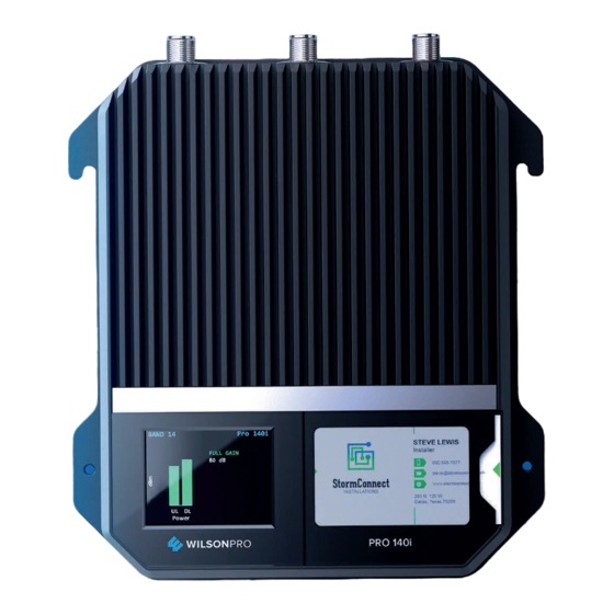
Page 4: About The Pro 140I
Pro 140i Industrial-Class, In-Building Cell Signal Amplifier Up to +27 dBm uplink power and 80 dB gain for maintaining connections with faraway cell towers Up to +27 dBm downlink power for improved indoor cell coverage area eXtended Dynamic Range (XDR) for continuous connectivity Color LCD screen, for easy installation and displaying detailed... - Page 5 14 carrier approval must be obtained for every installation. The Pro 140i also incorporates Wilson Electronics’ state-of-the-art XDR (eXtended Dynamic Range) technology that prevents signal overload conditions which can, in accordance with regulations, force the amplifier to shut down. When the Pro 140i...
-
Page 6: Key Features
Features Industrial-Class Amplification: Up to 100,000 sq. ft. of Band 14 (700MHz) coverage with a single amplifier (local carrier approval required for each installation). Extended Dynamic Range (XDR) for continuous connectivity: XDR allows the Pro 140i system to make automatic, real-time adjustments so it never shuts down due to a strong outside signal. -
Page 7: Post-Install Setup
Post-Install Setup The Pro 140i is designed with advanced internal programming, which allows it to automatically adjust for a variety of conditions, while still amplifying weak signals. Once the antenna cables are connected, turn the unit ON by inserting and twisting the power supply cord until it is securely locked in place. - Page 8 Installation Diagram A Wilson Lightning Surge Protector (859902) is recommended for all building installations. Make sure the protector is installed outside the building. Connect it to a suitable ground and in line, between the Outside Antenna and the Signal Amplifier. Combined Outside Antennas Band 14, 700 MHz...
-
Page 9: User Interface
User Interface The Pro 140i takes about thirty seconds to boot up. Once boot up is complete, the main screen will appear, showing the amplification and status of Band 14. Startup Screen “FULL GAIN” is displayed in green if there is a weak outside signal requiring the amplifier to operate with maximum allowable gain. - Page 10 (User Interface cont.) “XDR GAIN” is displayed in green, indicating that the amplifier has reduced its gain to accommodate a moderate to strong outside signal. The amplifier is functioning normally and no adjustments are needed. “OSCILLATION” is displayed in green, indicating that the amplifier has reduced its gain to accommodate a moderate oscillation condition.
- Page 11 (User Interface cont.) “OSCILLATION” is displayed in yellow, indicating a significant oscillation is occurring and band gain has been reduced below 60 dB. Reposition antennas (increase separation between inside and outside antennas and point in opposite directions) and then reboot (turn the unit off, then on) the Pro140i to reactivate Band 14 and maximize performance.
-
Page 12: Safety Guidelines
To uphold compliance with network protection standards, all active cellular devices must maintain at least 6 feet of separation distance from Panel and Dome antennas. Use only the power supply provided in this package. Use of a non-Wilson Electronics product may damage your equipment. - Page 13 Antenna Specifications This radio transmitter has been approved by the FCC and Innovation, Science and Economic Development (ISED) Canada to operate with the maximum permissible antenna gain below. Antenna that have a gain greater than the maximum gain indicated for any type listed are strictly prohibited for use with this device.
- Page 14 This device complies with Part 15 of FCC rules. Operation is subject to two conditions: (1) This device may not cause harmful interference, and (2) this device must accept any interference received, including interference that may cause undesired operation. Changes or modifications not expressly approved by Wilson Electronics could void the authority to operate this equipment.
-
Page 15: Warranty
MARKETING APPROVAL: Installer and end customer hereby grants to Wilson Electronics the express right to use installers or end customers company logo in marketing, sales, financial, and public relations materials and other communications solely to identify Customer as a Wilson Electronics customer. - Page 16 3301 East Deseret Drive, St. George, UT www.wilsonpro.com | support.wilsonpro.com www.wilsonpro.com | support.wilsonpro.com Copyright © 2023 Wilson Electronics. All rights reserved. Wilson Electronics products covered by U.S. patent(s) and pending application(s) For patents go to: weboost.com/us/patents NOT AFFILIATED WITH WILSON ANTENNA GDE000506_Rev02_07.20.23...
Need help?
Do you have a question about the WILSONPRO PRO 140i and is the answer not in the manual?
Questions and answers