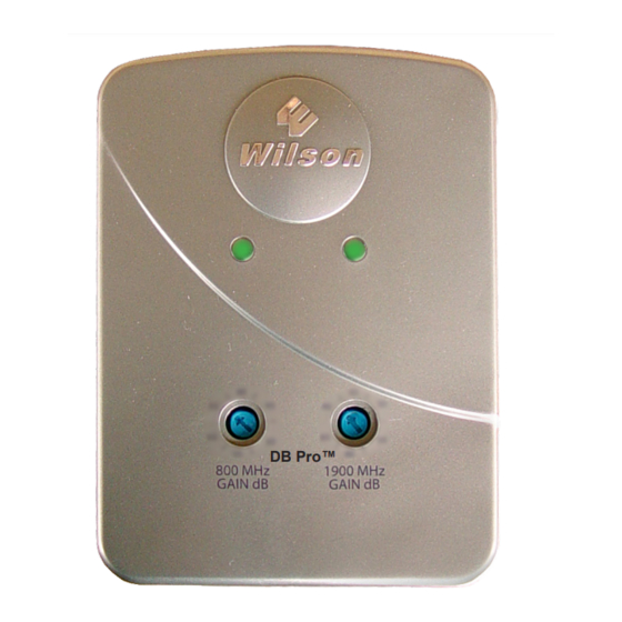
Wilson Electronics 271265 Installation Manuals
Db pro in-building wireless cellular smart technology amplifier
Hide thumbs
Also See for 271265:
- Installation manual (20 pages) ,
- Installation instructions manual (9 pages)
Table of Contents
Advertisement
Quick Links
Amplifier
Installation
Guide
Contents:
Before Getting Started / How It Works · · · · · · · · · · · · · 1
Antenna Options and Accessories · · · · · · · · · · · · · · · · 1
Installation Overview · · · · · · · · · · · · · · · · · · · · · · · · · · 2
Installation Diagram · · · · · · · · · · · · · · · · · · · · · · · · · · 2
Installing a Wilson Signal Booster · · · · · · · · · · · · · · · · 3
Powering Up a Wilson Signal Booster · · · · · · · · 4
Understanding the Signal Booster Lights · · · · · · 4
Warnings and Recommendations · · · · · · · · · · · · · · · · 5
Finding Signal Strength and Coverage Distance · · · · · · 5
Signal Booster Specifications · · · · · · · · · · · · · · · · 6
Guarantee and warranty · · · · · · · · · · · · · · · · Back Cover
DB Pro
Adjustable Gain
Smart Technology
In-Building
Dual Band
Cellular
SignalBooster
!
Warning: This manual contains
important safety and operating information.
Please read and follow the instructions
in this manual. Failure to do so could be
hazardous and result in damage to your
amplifier.
Advertisement
Table of Contents

Summary of Contents for Wilson Electronics 271265
-
Page 1: Table Of Contents
Amplifier Installation Guide DB Pro Adjustable Gain Smart Technology In-Building Dual Band Cellular SignalBooster Contents: Before Getting Started / How It Works · · · · · · · · · · · · · 1 Antenna Options and Accessories · · · · · · · · · · · · · · · · 1 Installation Overview ·... -
Page 2: Before Getting Started / How It Works
Installation Instructions for the Following Wilson Signal Boosters: DB Pro In-Building Wireless Cellular Smart Technology™ Amplifier Model # 271265 FCC ID: PWO271265 Before Getting Started This guide will help you properly install Wilson’s Adjustable Gain DB Pro - In-Building Wireless Signal Booster, with Smart Technology™. It is important to read through all of the installation steps for your particular application prior to installing any equipment. -
Page 3: Installation Overview
EASY TO INSTALL The following steps provide a summary of the signal booster/antenna installation process. However, they are not a substitute for the complete installation instructions on the following pages, which you should read thoroughly. Contact Wilson’s Technical Support Department with any questions at 866-294-1660. 1 Select a location to install the signal booster that is away from excessive heat, direct sunlight and moisture. -
Page 4: Installing A Wilson Signal Booster
Installing a Wilson Signal Booster Select a location to install the signal booster that is away from excessive heat, direct sunlight, moisture and that has proper ventilation. Do not place the signal booster in an air-tight enclosure. Recommended installation locations for in-building amplifiers are: •... -
Page 5: Powering Up A Wilson Signal Booster
Powering up a Wilson Signal Booster IMPORTANT! Ensure that all cell phones and cellular data cards within 50 feet of the inside antenna are turned off. 2. To verify proper installation of the signal booster and antennas, make sure that the distance between the inside and outside antennas is a minimum of 50 feet, 75 feet is better. -
Page 6: Warnings And Recommendations
Warnings and Recommendations Warning: The Yagi antenna must always be located so the back or side points to the inside antenna. Never point the front of the Yagi antenna toward the inside antenna – this is to prevent oscillation. Warning: Connecting the signal booster directly to the cell phone with use of an adapter will damage the cell phone. -
Page 7: Signal Booster Specifications
Returned Material Authorization (RMA) number supplied by Wilson Electronics. Wilson shall, at its option, either repair or replace the product. Wilson Electronics will pay for delivery of the repaired or replaced product back to the original consumer if located within the continental U.S. - Page 8 Adjustable Gain DB Pro Specifications Dual-Band Wireless FCC ID: PWO271265 800/1900 MHz Specifications Model Number 271265 Antenna connectors SMA Female Antenna impedance 50 ohms Dimensions 5.7 x 4.2 x 1.5 inch (14.0 x 10.8 x 3.9 cm) Weight 0.48 lbs (0.22 kg)


Need help?
Do you have a question about the 271265 and is the answer not in the manual?
Questions and answers