
Related Manuals for Wilson Electronics WILSONPRO ENTERPRISE 1300


Summary of Contents for Wilson Electronics WILSONPRO ENTERPRISE 1300
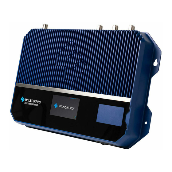
- Page 1 A Wilson Electronics Brand ENTERPRISE 1300/1300R In-Building Cell Signal Amplifier With Frequency-Specific Outside Antenna Ports and LTE Connected Remote Monitoring Installation Guide wilsonpro.com 866.294.1660...
-
Page 2: Table Of Contents
Index Package Contents About The Enterprise 1300 & 1300R Key Features Post Install Setup Menu System Safety Guidelines Specifications Warranty... -
Page 3: Package Contents
Package Contents Enterprise 1300 SKU 460149 & 460149F Enterprise 1300 Amplifier 100 ft. Wilson400 Cable (qty. 2) Wide Band Directional Antenna (qty. 1) 50 Ohm Lightning Surge Protector (qty. 1) Dome Antenna (qty. 1) 2 ft. Wilson400 Cable (qty. 1) Enterprise 1300R SKU 460150 &... -
Page 4: About The Enterprise 1300 & 1300R
Enterprise 1300 & 1300R In-Building Cell Signal Amplifier Systems Frequency-specific “split mode” option, facilitating separate outdoor antennas for different bands, resulting in improved indoor coverage. Remote system monitoring. Connects to WilsonPro Cloud service via internal, pre-activated LTE modem. High max uplink power (up to +26 dBm): will reach far-away cell tower. - Page 5 The Enterprise 1300 & 1300R cell signal amplifier systems also incorporates Wilson Electronics’ state-of-the-art XDR (eXtended Dynamic Range) technology that prevents signal overload conditions which can, in accordance with regulations, force the amplifier to shut down.
-
Page 6: Key Features
Features Extended Dynamic Range (XDR) for continuous connectivity: XDR lets the Enterprise 1300 & 1300R systems work with an incoming signal and never shuts down due to a strong outside signal. Simple Wall-Mount & Rack Mount Installation: An indoor and outdoor port(s) are located on top of the amplifier for easy antenna connections, while an exposed mounting flange on each amplifier provides for simple installation. -
Page 7: Post Install Setup
Post Install Setup The Enterprise 1300 & 1300R systems are designed with advanced internal programming, which allows it to automatically adjust for a variety of conditions, while still amplifying weak signals. THE SERVER PORT ANTENNAS WILL BE USED TO PROVIDE COVERAGE TO DIFFERENT AREAS WITHIN A BUILDING AND WILL BE INSTALLED WITH A MINIMUM OF 10 METERS... -
Page 8: Menu System
Menu System The Enterprise 1300 & 1300R takes about 8 seconds to boot up. Once boot up is complete, the home screen will appear, showing the amplification and status of each port and band. Home Screen Start Up Screen Band Menu Color Description A solid green light indicates that a band is operating correctly with maximum allowable gain. - Page 9 (MENU SYSTEM cont.) A red light indicates a band has been shut down because of a severe oscillation condition or repeated oscillation. Reposition antennas (increase separation between indoor and outdoor antennas, and point in opposite directions) and then reboot (turn the unit off &...
- Page 10 Settings Screen Tap ‘Settings Icon’ to view the Settings Screen. There are 5 Settings Screens represented by “tabs”. Tap the tab heading to view each Settings Screen. Note: Bands and Ports are disabled or enabled from the Cloud or Local Configuration Utility only. IN-BUILDING CELL SIGNAL AMPLIFIER ENTERPRISE 1300 &...
- Page 11 (MENU SYSTEM - SETTINGS SCREEN cont.) Ethernet Settings Tab Modem Settings Tab ENTERPRISE 1300 & 1300R IN-BUILDING CELL SIGNAL AMPLIFIER...
- Page 12 (MENU SYSTEM - SETTINGS SCREEN cont.) Cloud Communication Settings Tab Note: The Reset Local Comm button (button name will likely change) is used in case the user has configured the amplifier such that the Local Configuration Utility is not accessible, e.g., if the communication preferences are set to “LTE Only”.
- Page 13 (MENU SYSTEM - SETTINGS SCREEN cont.) Split Mode Configuration Split Mode is configured from the Local Configuration Utility and should be sent when using separate Donor/Outside Antennas for Band 4/25, Band 5, and Band 12/13. To go back to the Home Screen top on the Home Icon (in the lower right corner). ENTERPRISE 1300 &...
- Page 14 Band Status Screens To view specific band information (such as the strength of the received uplink & downlink signal, outside signal strength, and amplifier gain status) tap the desired band on the home screen. Oscillation Example IN-BUILDING CELL SIGNAL AMPLIFIER ENTERPRISE 1300 &...
- Page 15 (MENU SYSTEM - SETTINGS SCREEN cont.) Shutdown Example ENTERPRISE 1300 & 1300R IN-BUILDING CELL SIGNAL AMPLIFIER...
- Page 16 Connectivity Status Screens Ethernet Status Icon The three icons in the upper right provide status related to the Ethernet connection, Cloud connection, and USB device (if inserted). Cloud Status IN-BUILDING CELL SIGNAL AMPLIFIER ENTERPRISE 1300 & 1300R...
- Page 17 (MENU SYSTEM - CONNECTIVITY STATUS SCREENS cont.) USB Status ENTERPRISE 1300 & 1300R IN-BUILDING CELL SIGNAL AMPLIFIER...
-
Page 18: Safety Guidelines
To uphold compliance with network protection standards, all active cellular devices must maintain at least 6 feet of separation distance from Panel and Dome antennas. Use only the power supply provided in this package. Use of a non-Wilson Electronics product may damage your equipment. - Page 19 Antenna Kit Options The following accessories are certified by the FCC to be used with the ENTERPRISE 1300/1300R. This radio transmitter 4726A-460050 has been approved by Innovation, Science and Economic Development Canada to operate with the antenna types listed below, with the maximum permissible gain indicated. Antenna types not included in this list that have a gain greater than the maximum gain indicated for any type listed are strictly prohibited for use with this device.
-
Page 20: Specifications
Specifications Model Number 460149 / 460149F / 460150 / 460150F FCC ID PWO460049 / PWO460049 / PWO460050 / PWO460050 IC ID 4726A-460049 / 4726A-460049 / 4726A-460050 / 4726A-460050 Connectors N-Connectors Antenna Impedance 50 Ohms Frequency 698-716 MHz, 729-756 MHz, 777-787 MHz, 824-894 MHz, 1850-1995 MHz, 1710-1755/2110-2155 MHz Power output for single cell Band12/17 Band13... -
Page 21: Warranty
MARKETING APPROVAL: Installer and end customer hereby grants to Wilson Electronics the express right to use installers or end customers company logo in marketing, sales, financial, and public relations materials and other communications solely to identify Customer as a Wilson Electronics customer. - Page 22 Notes support.wilsonpro.com 866.294.1660 NEED HELP? IN-BUILDING CELL SIGNAL AMPLIFIER ENTERPRISE 1300 & 1300R...
- Page 23 Notes support.wilsonpro.com 866.294.1660 NEED HELP? ENTERPRISE 1300 & 1300R IN-BUILDING CELL SIGNAL AMPLIFIER...
- Page 24 Copyright © 2016 Wilson Electronics. All rights reserved. Copyright © 2019 Wilson Electronics. All rights reserved. Wilson Electronics products covered by U.S. patent(s) and pending application(s) Wilson Electronics products covered by U.S. patent(s) and pending application(s) For patents go to: weboost.com/us/patents For patents go to: weboost.com/us/patents...
Need help?
Do you have a question about the WILSONPRO ENTERPRISE 1300 and is the answer not in the manual?
Questions and answers