Table of Contents
Advertisement
Quick Links
Advertisement
Table of Contents

Subscribe to Our Youtube Channel
Related Manuals for Teltonika FMU125


Summary of Contents for Teltonika FMU125
- Page 1 FMU125 Quick Manual Advanced 3G terminal with v1.5 RS485/RS232 interfaces...
-
Page 2: Table Of Contents
How to install USB drivers (Windows) ............7 Configuration (Windows) ................... 7 Quick SMS configuration..................8 Mounting recommendations ............. 10 LED indications ..................11 Characteristics ..................11 Basic characteristics .................... 11 Electrical characteristics ..................13 Safety information ................14 FMU125 | Wiki... -
Page 3: Know Your Device
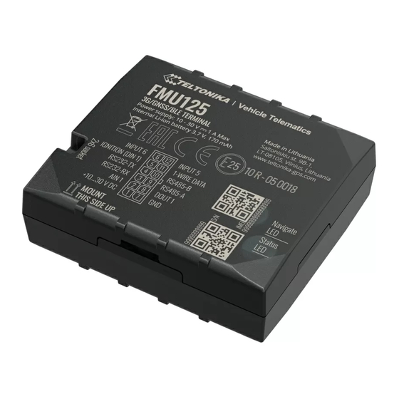
Know your device Figure 1 FMU125 device view FMU125 | Wiki... -
Page 4: Pinout
Pinout Table 1 FMU125 2x6 socket pinout Pin number Pin name Description VCC (10-30) V DC (+) Power supply (+10-30 V DC). Analog input, channel 1. Input range: AIN 1/DIN 2 10-30 V DC / Digital input, channel 2. RS232 – RX Input for data receive through RS232 RS232 –... -
Page 5: Wiring Scheme
Wiring scheme Figure 3 FMU125 Wiring scheme Automotive relay FMU125 | Wiki... -
Page 6: Set Up Your Device
Set up your device How to insert SIM card and connect the battery 1. Gently remove FMU125 cover using plastic pry tool from both sides. 2. Insert SIM card as shown with PIN request disabled or read our Wiki how to enter it later in Teltonika Configurator. -
Page 7: Pc Connection (Windows)
Setup will continue installing the driver and eventually the confirmation window will appear. Click Finish to complete the setup. 1. Power-up FMU125 with DC voltage (10 – 30 V) power supply Configuration (Windows) using supplied power cable. LED’s should start blinking, see “LED indications”. -
Page 8: Quick Sms Configuration
GPRS settings can be configured and Data Acquisition – where data acquiring parameters can be configured. More details about FMU125 configuration using Configurator can be found in our Wiki. Quick SMS configuration Figure 10 Configurator Status window FMU125 | Wiki... - Page 9 • server every 120 seconds 2005 – Port • After successful SMS configuration, FMU125 device will synchronize 2006 – Data sending protocol (0 • time and update records to configured server. Time intervals and – TCP, 1 – UDP) default I/O elements can be changed by using...
-
Page 10: Mounting Recommendations
▬ When the module is connected, measure the voltage again to make sure it did not decrease. ▬ It is recommended to connect to the main power cable in the fuse box. ▬ 3 A, 125 V external fuse shall be used. FMU125 | Wiki... -
Page 11: Led Indications
UMTS: Max. 384Kbps (DL)/Max.384Kbps (UL) boot mode GPRS: Max. 107Kbps (DL)/Max.85.6Kbps (UL) Data transfer Data support SMS (text/data) Power Input voltage range 10-30 V DC with overvoltage protection Back-up battery 170 mAh Li-Ion battery 3.7 V (0.63 Wh) FMU125 | Wiki... - Page 12 65 x 56,6 x 20,6 mm (L x W x H) Weight 55 g Operating environment Operating temperature -40 °C to +85 °C (without battery) Storage temperature -40 °C to +85 °C (without battery) Operating humidity 5% to 95% non-condensing FMU125 | Wiki...
-
Page 13: Electrical Characteristics
Input voltage (Recommended Operating Output Supply Voltage 1-Wire Conditions) Supply voltage +4.5 +4.7 Input Voltage threshold (DIN 1) Output inner resistance Ω Input Voltage threshold (DIN 2) Output current (U > 3.0 V) Short circuit current (U = 0) FMU125 | Wiki... -
Page 14: Safety Information
All related devices must meet the requirements of EN 60950-1 standard. The device FMU125 is not designed as a navigational device for boats. The device is susceptible to water and humidity. Do not disassemble the device. If the device is... -
Page 15: Certification And Approvals
• FMU125 E-Mark • FMU125 RoHS • FMU125 Declaration of device operation temperature • This sign on the package means that it is necessary to read the User‘s Manual before your start using the device. Full User‘s Manual version can be found in our Wiki. -
Page 16: Warranty
More information can be found at teltonika.lt/warranty-repair • Replaced with a new product • Replaced with an equivalent repaired product fulfilling the same functionality • TELTONIKA can also repair products that are out of warranty at an agreed cost. FMU125 | Wiki...
Need help?
Do you have a question about the FMU125 and is the answer not in the manual?
Questions and answers