Teltonika FMC13A Quick Manual
Advanced lte terminal with flexible inputs configuration
Hide thumbs
Also See for FMC13A:
- First start-up quick start manual (8 pages) ,
- General description (5 pages) ,
- Manual (3 pages)
Table of Contents
Advertisement
Quick Links
Advertisement
Table of Contents

Related Manuals for Teltonika FMC13A


Summary of Contents for Teltonika FMC13A
- Page 1 FMC13A ADVANCED LTE TERMINAL WITH FLEXIBLE INPUTS CONFIGURATION Quick Manual v1.5...
-
Page 2: Table Of Contents
Quick SMS configuration ....................................10 Mounting recommendations..................................12 Basic characteristics ......................................13 LED indications ......................................... 13 Electrical characteristics ....................................16 Safety information ......................................18 Certification ........................................19 Warranty ........................................... 20 Warranty disclaimer ....................................... 20 Quick Manual v1.5 // FMC13A Telematics... -
Page 3: Know Your Device
KNOW YOUR DEVICE TOP VIEW BOTTOM VIEW TOP VIEW (WITHOUT COVER) (WITHOUT COVER) NAVIGATE GNSS STATUS ANTENA MICRO-SIM BATTERY SLOT SOCKET SOCKET Quick Manual v1.5 // FMC13A Telematics... -
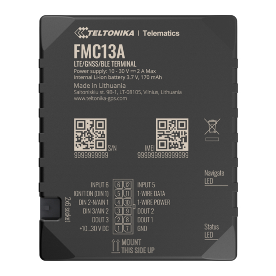
Page 4: Pinout
+3,8 V output for 1–Wire GND (-) 1WIRE POWER DC (―) devices Digital output, channel 1WIRE DATA Data for 1–Wire devices DOUT 1 1. Open collector output. Max. 0,5 A DC INPUT 5V RX EXT (LVCAN - RX) Quick Manual v1.5 // FMC13A Telematics... -
Page 5: Wiring Scheme
INPUT 6 INPUT 5 IBUTTON DIN1 1WIRE DATA DIN2-N/AIN1 1WIRE POWER DIN3/AIN2 DOUT2 DOUT3 DOUT1 FUEL GAUGE +10...30 V DC BUZZER ANALOG POWER SUPPLY STARTER LLS SENSOR DOOR SENSOR 10 - 30V DC CENTRAL LOCK Quick Manual v1.5 // FMC13A Telematics... -
Page 6: Set Up Your Device
Make sure that corner is pointing outward product casing is closed from slot. SIM slot 1 is closer correctly. to PCB, SIM slot 2 is the top one. wiki.teltonika-gps.com/view/ FMC13A_Security_info wiki.teltonika-gps.com/view/ 2 Teltonika_Configurator Quick Manual v1.5 // FMC13A Telematics... -
Page 7: Pc Connection (Windows)
PC CONNECTION (WINDOWS) Power-up FMC13A with DC voltage (10 – 30 V) power supply using supplied power cable. LED’s should start blinking, see “LED indications”. Connect device to computer using Micro-USB cable or Bluetooth connection: • Using Micro-USB cable •... -
Page 8: Configuration
CONFIGURATION At first FMC13A device will have default factory settings set. These settings should be changed according to the users needs. Main configuration can be performed via Teltonika Configurator software. Get the latest Configurator version from here . Configurator operates on Microsoft Windows OS and uses prerequisite MS .NET Framework. Make sure you have the correct version installed. - Page 9 Most important configurator section is GPRS – where all your server and GPRS settings can be configured and Data Acquisition – where data acquiring parameters can be configured. More details about FMC13A configuration using Configurator can be found in our Wiki wiki.teltonika-gps.com/view/FMC13A_Status_info wiki.teltonika-gps.com/view/FMC13A_Status_info#GNSS_Info wiki.teltonika-gps.com/view/FMC13A_Status_info#GSM_Info wiki.teltonika-gps.com/view/FMC13A_Status_info#I.2FO_Info wiki.teltonika-gps.com/view/FMC13A_Status_info#Maintenance...
-
Page 10: Quick Sms Configuration
2003 – APN password (if there are no APN password, empty field should be left) SERVER SETTINGS: 2004 – Domain 2005 – Port 2006 – Data sending protocol (0 – TCP, 1 – UDP) Quick Manual v1.5 // FMC13A Telematics... - Page 11 120 seconds is off After successful SMS configuration, FMC13A device will synchronize time and update records to configured server. Time intervals and default I/O elements can be changed by using Teltonika Configurator SMS parameters wiki.teltonika-gps.com/view/Teltonika_Configurator...
-
Page 12: Mounting Recommendations
If the wire is fixed with the bolt, the loop must be connected to the end of the wire. • For better contact scrub paint from the spot where loop is going to be connected. Quick Manual v1.5 // FMC13A Telematics... -
Page 13: Basic Characteristics
Celluar Blinking fast for a Modem activity short time Technology LTE Cat 1, UMTS Device is not working or Device is in 3G bands WCDMA: B2/B4/B5 boot mode 4G bands LTE FDD: B2/B4/B5/B12/B13 Quick Manual v1.5 // FMC13A Telematics... - Page 14 At 12V < 2A Max. (with full Load / Memory 128MB internal flash memory Peak) Physical specification Bluetooth Dimensions 77 x 62 x 20 mm (L x W x H) Specification 4.0 + LE Quick Manual v1.5 // FMC13A Telematics...
- Page 15 Digital Input 1, Accelerometer, -20 °C to +45 °C for 1 month Battery storage Ignition detection External Power Voltage, Engine RPM temperature -20 °C to +35 °C for 6 months (CAN Adapters, OBDII dongle) Features Sensors Accelerometer Quick Manual v1.5 // FMC13A Telematics...
-
Page 16: Electrical Characteristics
0.33 30 V, Range 1 Digital input Additional error on 30 V, Range 1 Input resistance (DIN1) kΩ Input Voltage Input resistance (DIN2) 38.45 kΩ (Recommended Operating Conditions), Input resistance (DIN3) kΩ Range 2 Quick Manual v1.5 // FMC13A Telematics... - Page 17 Output inner resistance Ω Output current (U > 3.0 V) Short circuit current (U = 0) Negative input Input resistance 38.45 kΩ Input voltage Supply (Recommended voltage Operating Conditions) Input voltage threshold Sink current Quick Manual v1.5 // FMC13A Telematics...
-
Page 18: Safety Information
All related devices must meet the requirements of EN 60950-1 standard. • The device FMC13A is not designed as a navigational CAUTION: Risk of explosion if battery is replaced by an incorrect type. Dispose of used batteries device for boats. -
Page 19: Certification
Full User ‘s Manual version can be found mixed with general household waste. in our Wiki https://wiki.teltonika.lt/view/FMC13A_RoHS CHECK ALL CERTIFICATES All newest certificates may be found in our Wiki wiki.teltonika-gps.com/view/FMC13A_Certification_%26_Approvals Quick Manual v1.5 // FMC13A Telematics... -
Page 20: Warranty
WARRANTY TELTONIKA guarantees its products to be free of any manufacturing defects for a period of 24 months. With additional agreement we can agree on a different warranty period, for more detailed information please contact our sales manager. Contact us teltonika-iot-group.com/about-us/contacts/ All batteries carry a reduced 6 month warranty period.
Need help?
Do you have a question about the FMC13A and is the answer not in the manual?
Questions and answers