Table of Contents
Advertisement
Quick Links
Advertisement
Table of Contents

Related Manuals for Advantech PCA-6004V-00A1


Summary of Contents for Advantech PCA-6004V-00A1
- Page 1 PCA-6004 Full-sized PCI/ISA-bus CPU card with VIA C3...
- Page 2 Copyright notice This document is copyrighted, 2000, by Advantech Co., Ltd. All rights are reserved. Advantech Co., Ltd. reserves the right to make improve- ments to the products described in this manual at any time without notice. No part of this manual may be reproduced, copied, translated or transmitted in any form or by any means without the prior written permission of Advantech Co., Ltd.
- Page 3 A Message to the Customer Advantech customer services Each and every Advantech product is built to the most exacting specifications to ensure reliable performance in the harsh and demanding conditions typical of industrial environments. Whether your new Advantech equipment is destined for the laboratory or the...
- Page 4 i r e i r a o l l & ) s t l a i l e l i - t : t e t l a...
- Page 5 Advantech assumes no liability under the terms of this warranty as a consequence of such events. If an Advantech product is defective, it will be repaired or replaced at no charge during the warranty period. For out-of-warranty repairs, you will be billed according to the cost of replacement materials, service time and freight.
- Page 6 Initial Inspection Before you begin installing your card, please make sure that the following materials have been shipped: • 1 PCA-6004 PCI/ISA single board computer • 1 PCA-6004 startup Manual • 1 CD driver utility and manual (in PDF format) •...
-
Page 7: Table Of Contents
Table Chapter 1 Hardware Configuration ....... 1 1.1 Introduction ................2 1.2 Features ................. 3 1.3 Specifications ................ 4 1.3.1 System ................. 4 1.3.2 Memory ............... 4 1.3.3 Input/Output ..............4 1.3.4 VGA interface ............. 5 1.3.5 Ethernet LAN ............. 5 1.3.6 AC-97 Audio Interface .......... - Page 8 2.6 10/100Base-T Ethernet Connector (CN8) ....17 2.7 Serial Ports (CN9: COM1; CN10: COM2) ....17 2.8 PS/2 Keyboard and Mouse Connector (CN11) ..... 18 2.9 External Keyboard Connector (CN12) ......18 2.10 Infrared (IR) Connector (CN13) ........19 2.11 CPU Fan Connector (CN14) .......... 19 2.12 Front Panel Connectors (CN16, CN17, CN18, CN19, CN21 and CN29) ..............
- Page 9 3.4.8 Gate A20 Option ............29 3.4.9 Typematic Rate Setting ..........29 3.4.10 Typematic Rate (Chars/Sec) ........30 3.4.11 Typematic Delay (msec) ......... 30 3.4.12 Security Option ............30 3.4.13 OS Select for DRAM > 64MB ....... 30 3.4.14 Video BIOS Shadow ..........31 3.4.15 VIA C3 Clock Ratio ..........
- Page 10 3.6.8 UART 2 Mode Select ..........37 3.6.9 Onboard Parallel Port (378H/IRQ7) ......37 3.6.10 Onboard Parallel Port Mode (ECP + EPP) .... 37 3.6.11 ECP Mode Use DMA ..........37 3.6.12 EPP Mode Select ............ 37 3.7 Power Management Setup ..........38 3.7.1 ACPI function ............
- Page 11 Chapter 4 AGP SVGA Setup ........47 4.1 Before You Begin ............... 48 4.2 Features ................48 4.3 Installation ................49 Chapter 5 LAN Configuration ........51 5.1 Introduction ................ 52 5.2 Features ................52 5.3 Driver Installation .............. 53 5.4 Windows 9X Drivers Setup Procedure ......
- Page 12 B.20 System I/O Ports ............. 89 B.21 DMA Channel Assignments ......... 90 B.22 Interrupt Assignments ........... 90 B.23 1st MB Memory Map ............ 91 23: 1st MB memory map ............91 B.24 PCI Bus Map ..............91 Figure Figure 3-1: Award BIOS Setup initial screen ..........26 Figure 3-2: Standard CMOS features screen ..........
- Page 13 Table Table 1-1: Jumpers ......................6 Table 1-2: Connectors ...................... 7 Table 1-3: CMOS clear (J1) .................... 10 Table 1-4: Watchdog timer output (J2) ................10 Table 1-5: DIMM module allocation table ................. 11 Table 1-6: DIMM memory capacity sample calculation ..........11 Table 2-1: Serial port connections (COM1, COM2) ............
-
Page 15: Chapter 1 Hardware Configuration
Hardware Configuration This chapter gives background informa- tion on the PCA-6004. It will provide instructions on how card configuration to match your application, and PC installa- tion. Sections include: • Introduction • Features • Specifications • Board Layout • Jumpers and Connectors •... -
Page 16: Introduction
Introduction The PCA-6004 Series all-in-one industrial grade single board computer is designed for embedded applications where low power consumption and fanless operation are major concerns. Providing full industrial features to meet most industrial application requirements, it uses VIA's C3 processor with the Apollo PLE133 chipset. The VIA C3 CPU is a high performance but low power processor. -
Page 17: Features
Proper system configuration and management. A remote monitoring interface is reserved for remote management through Ethernet by using Advantech's SNMP-1000 system management module. 3. ATX soft power switch: Through the BIOS, the power button can be defined as a "Standby"... -
Page 18: Specifications
• Power On by Alarm: Powers up your computer at a certain time • Virus warning: During and after system boot-up, any attempt to write to the boot sector or partition table of the hard disk drive will halt the system. In this case, a warning message will be displayed. -
Page 19: Vga Interface
• Serial ports: Two RS-232 ports with 16C550 UARTs (or compatible) with 16-byte FIFO buffer. Supports speeds up to 115.2 Kbps. Ports can be individually configured to COM1, COM2 or disabled • Keyboard and PS/2 mouse connector: A 6-pin mini-DIN connector is located on the mounting bracket for easy connection to a keyboard or PS/2 mouse. -
Page 20: Mechanical And Environmental Specifications
1.3.8 Mechanical and environmental specifications • Operating temperature: 0 ~ 60° C (32 ~ 140° F) • Storage temperature: -20 ~ 70° C (-4 ~ 158° F) • Humidity: 20 ~ 95% non-condensing • Power supply voltage: +5 V, ±12 V •... - Page 21 Table 1-2: Connectors Label Function Primary IDE connector Secondary IDE connector Floppy drive connector Parallel port USB port VGA connector 10/100Base-T Ethernet connector Serial port: COM1 CN10 Serial port: COM2 CN11 PS/2 keyboard and mouse connector CN12 External keyboard connector CN13 Infrared (IR) connector CN14...
-
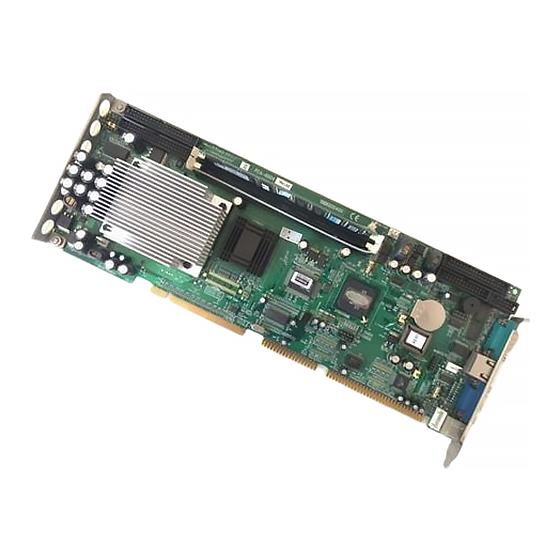
Page 22: Board Layout: Jumper And Connector
Board Layout: Jumper and Connector Locations PCA-6004 User's Manual... -
Page 23: Safety Precautions
Safety Precautions Warning! Always completely disconnect the power cord from your chassis whenever you work with the hardware. Do not make connections while the power is on. Sensitive electronic components can be damaged by sudden power surges. Only experienced electronics personnel should open the PC chassis. Caution! Always ground yourself to remove any static charge before touching the CPU card. -
Page 24: Cmos Clear (J1)
1.7.2 CMOS clear (J1) The PCA-6004 CPU card contains a jumper that can erase CMOS data and reset the system BIOS information. Normally this jumper should be set with pins 1-2 closed. If you want to reset the CMOS data, set J1 to 2-3 closed for just a few seconds, and then move the jumper back to 1- 2 closed. -
Page 25: System Memory
System Memory The PCA-6004 has two 168-pin dual inline memory module sockets (DIMMs). All these sockets use 3.3 V unbuffered synchronous DRAMs (SDRAM). DIMMs are available in capacities of 16, 32, 64, 128, 256 or 512 MB. The sockets can be filled in any combination with DIMMs of any size, giving a total memory size between 16 MB and 1 GB. -
Page 26: Memory Installation Procedures
• SDRAM chips are usually thinner and have higher pin density than EDO chips. • Chips with 9 chips/side support ECC; chips with 8 chips/side do not support ECC. Memory Installation Procedures To install DIMMs, first make sure the two handles of the DIMM socket are in the "open"... -
Page 27: Chapter 2 Connecting Peripherals
Connecting Peripherals This chapter tells how to connect periph- erals, switches and indicators to the PCA-6004 board. You can access most of the connectors from the top of the board while it is installed in the chassis. If you have a number of cards installed, or your chassis is very tight, you may need to partially remove the card to make all the connections. -
Page 28: Primary (Cn1) And Secondary (Cn2) Ide Connectors
Primary (CN1) and Secondary (CN2) IDE Connectors You can attach up to four IDE (Integrated Device Electronics) drives to the IDE connectors. The primary (CN1) and secondary (CN2) connec- tors can each accommodate two drives. Wire number 1 on the cable is red or blue and the other wires are gray. Connect one end to connector CN1 or CN2 on the CPU card. -
Page 29: Floppy Drive Connector (Cn3)
Floppy Drive Connector (CN3) You can attach up to two floppy disk drives to the PCA-6004's onboard controller. You can use any combination of 5.25" (360 KB / 1.2 MB) and/or 3.5" (720 KB / 1.44/2.88 MB) drives. The card comes with a 34-pin daisy-chain drive connector cable. On one end of the cable is a 34-pin flat-cable connector. -
Page 30: Usb Port (Cn6)
To install the bracket, find an empty slot in your chassis. Unscrew the plate that covers the end of the slot. Screw in the bracket in place of the plate. Next, attach the flat-cable connector to CN4 on the CPU card. Wire 1 of the cable is red or blue, and the other wires are gray. -
Page 31: 10/100Base-T Ethernet Connector (Cn8)
10/100Base-T Ethernet Connector (CN8) The PCA-6004 is equipped with a high-performance 32-bit PCI-bus Ethernet interface, which is fully compliant with IEEE 802.3/u 10/100 Mbps CSMA/CD standards. It is supported by all major network operating systems and is 100% Novell NE-2000 compatible. An onboard RJ-45 jack provides convenient 10/100Base-T RJ-45 opera- tion. -
Page 32: Ps/2 Keyboard And Mouse Connector (Cn11)
The IRQ and address ranges for both ports are fixed. However, if you want to disable the port or change these parameters later, you can do this in the system BIOS setup. Different devices implement the RS-232 standard in different ways. If you are having problems with a serial device, be sure to check the pin assignments for the connector. -
Page 33: Infrared (Ir) Connector (Cn13)
2.10 Infrared (IR) Connector (CN13) CN13 This connector supports the optional wireless infrared transmitting and receiving module. This module mounts on the system case. You must configure the setting through the BIOS setup (see Chapter 3). 2.11 CPU Fan Connector (CN14) CN14 PIN 1 This connector supports a cooling fan with tachometer output. -
Page 34: Front Panel Connectors (Cn16, Cn17, Cn18, Cn19, Cn21 And Cn29)
2.12 Front Panel Connectors (CN16, CN17, CN18, CN19, CN21 and CN29) There are several external switches to monitor and control the PCA-6004. CN21 CN18 CN19 CN29 CN17 CN16 2.12.1 Keyboard lock and power LED (CN16) CN16 is a 5-pin connector for the power on LED. Refer to Appendix B for detailed information on the pin assignments. -
Page 35: Reset (Cn18)
You can connect an LED to connector CN19 to indicate when the HDD is active. 2.12.5 SM Bus Connector (CN29) This connector is reserved for Advantech's SNMP-1000 HTTP/SNMP Remote System Manager. The SNMP-1000 allows users to monitor the internal voltages, temperature and fans from a remote computer through an Ethernet network. -
Page 36: Atx Power Control Connectors (Cn20 And Cn21)
2.13 ATX Power Control Connectors (CN20 and CN21) CN20 2.13.1 ATX feature connector (CN20) and soft power switch connector (CN21) The PCA-6004 can support an advanced soft power switch function if an ATX power supply is used. To enable the soft power switch function: 1. -
Page 37: Controlling The Soft Power Switch
Important: Make sure that the ATX power supply can take at least a 720 mA load on the 5 V standby lead (5VSB). If not, you may have difficulty powering on your system and/or supporting the "Wake-on-LAN" function. 2.13.2 Controlling the soft power switch Users can also identify the current power mode through the system's power LED (see Section 2.13.1). - Page 38 PCA-6004 User's Manual...
-
Page 39: Chapter 3 Award Bios Setup
Award BIOS Setup This chapter describes how to set the card’s BIOS configuration data. -
Page 40: Introduction
CPU. If there is no number assigned to the patch code, please contact Advantech’s applications engineer to obtain an up-to-date patch code file. This will ensure that your CPU’s system status is valid. After ensuring that you have a number assigned to the patch code, press <Del>... -
Page 41: Standard Cmos Setup
Standard CMOS Setup Choose the “Standard CMOS Features” option from the “Initial Setup Screen” menu, and the screen below will be displayed. This menu allows users to configure system components such as date, time, hard disk drive, floppy drive, display, and memory. Figure 3-2: Standard CMOS features screen 3.3.1 CMOS RAM backup The CMOS RAM is powered by an onboard button cell battery. -
Page 42: Advanced Bios Features
Advanced BIOS Features The “Advanced BIOS Features” screen appears when choosing the “Advanced BIOS Features” item from the “Initial Setup Screen” menu. It allows the user to configure the CPU card according to his particular requirements. Below are some major items that are provided in the Advanced BIOS Features screen. -
Page 43: Cpu L2 Cache Ecc Checking
3.4.3 CPU L2 Cache ECC Checking Enabling allows CPU L2 cache checking. The commands are “Enabled” or “Disabled.” 3.4.4 First/Second/Third/Other Boot Device The BIOS tries to load the OS with the devices in the sequence selected. Choices are: Floppy, LS/ZIP, HDD, SCSI, CDROM, LAN, Disabled. 3.4.5 Swap Floppy Drive Logical name assignments of floppy drives can be swapped if there is more than one floppy drive. -
Page 44: Typematic Rate (Chars/Sec)
3.4.10 Typematic Rate (Chars/Sec) BIOS accepts the following input values (characters/second) for typematic rate: 6, 8, 10, 12, 15, 20, 24, 30. 3.4.11 Typematic Delay (msec) Typematic delay is the time interval between the appearance of two consecutive characters, when holding down a key. The input values for this category are: 250, 500, 750, 1000 (msec). -
Page 45: Video Bios Shadow
3.4.14 Video BIOS Shadow Enable copies video BIOS to shadow RAM for performnace improving. Choices are Enable, Disable. Figure 3-3-1: Advanced BIOS features screen (2) Figure 3-3-2: Advanced BIOS features screen (3) Chapter 3 Award BIOS Setup... -
Page 46: Via C3 Clock Ratio
3.4.15 VIA C3 Clock Ratio This setting allows changing the CPU clock speed in case of special thermal concerns. The choices are: Default Auto detect CPU speed 400 MHz X3.5 467 MHz 533 MHz X4.5 600 MHz 667 MHz X5.5 733 MHz 800 MHz X6.5 ~ 12 These ratios are reserved for future CPU use. -
Page 47: Dram Clock
3.5.1 DRAM Clock This item allows you to control the DRAM speed. The Choice: Host Clock, CLK-33M. 3.5.2 SDRAM Cycle Length When synchronous DRAM is installed, the number of clock cycles of CAS latency depends on the DRAM timing. Do not reset this field from the default value specified by the system designer. -
Page 48: Onchip Usb
aperture is a portion of the PCI memory address range dedicated for graphics memory address space. Host cycles that hit the aperture range are forwarded to the AGP without any translation. The Choice: 4M, 8M, 16M, 32M, 65M, 128M, 256M. 3.5.8 Onchip USB This should be enabled if your system has a USB installed on the system board and you want to use it. -
Page 49: Pci Delay Transaction
3.5.14 PCI Delay Transaction The chipset has an embedded 32-bit posted write buffer to support delay transactions cycles. Select Enabled to support compliance with PCI specification version 2.1. The choice: Enabled, Disabled 3.5.15 PCI#2 Access #1 Retry When disabled, PCI#2 will not be disconnected until access finishes (difault). -
Page 50: On-Chip Primary/Secondary Pci Ide
3.6.1 On-Chip Primary/Secondary PCI IDE If you enable IDE HDD Block Mode, the enhanced IDE driver will be enabled. Leave IDE HDD Block Mode on the default setting. 3.6.2 IDE Primary Master/Slave PIO/UDMA Mode, IDE Secondary Master/Slave PIO/UDMA Mode (Auto) Each channel (Primary and Secondary) has both a master and a slave, making four IDE devices possible. -
Page 51: Uart 2 Mode Select
The settings are Auto 3F8/IRQ4, 2F8/IRQ3, 3E8/IRQ4, 2E8/IRQ3, and Disabled for the on-board serial connector. 3.6.8 UART 2 Mode Select This item allows you to select UART mode. The choices: HPSIR, ASKIR, Standard. 3.6.9 Onboard Parallel Port (378H/IRQ7) This field sets the address of the on-board parallel port connector. You can select either 3BC/IRQ7, 378/IRQ7, 278/IRQ5 or Disabled. -
Page 52: Power Management Setup
Power Management Setup The power management setup controls the CPU card’s “green” features to save power. The following screen shows the manufactur- er’s defaults: Figure 3-6: Power management setup screen 3.7.1 ACPI function This item allows you to enable/disable the Advanced Configuration and Power Management (ACPI). -
Page 53: Pm Control By Apm
) t l . t n s e l l l a . n i . t n . r h , . r . r h . n i . t n , . n , . n . n i . -
Page 54: Modem Use Irq
3.7.6 MODEM Use IRQ This determines the IRQ in which the MODEM can use.The choices: 3, 4, 5, 7, 9, 10, 11, NA. 3.7.7 Soft-Off by PWRBTN If you choose “Instant-Off”, then pushing the ATX soft power switch button once will switch the system to “system off” power mode. You can choose “Delay 4 sec.”... -
Page 55: Wake Up Event
3.8 Wake Up Event Figure 3-7: Wake-up event screen 3.8.1 VGA When Enabled, you can set the VGA awakens the system. 3.8.2 LPT & COM When On of LPT & COM, any activity from one of the listed system peripheral devices or IRQs wakes up the system. 3.8.3 HDD &... -
Page 56: Power On By Modem
3.8.5 Power On by Modem When enabled, an input signal on the serial Ring Indicator (RI) line (in other words, an incoming call on the modem) awakens the system from a soft off state. The Choice: Enable, Disable. 3.8.6 Power On by Alarm When enabled, you can set the date and time at which the RTC (real- time clock) alarm awakens the system from Suspend mode. -
Page 57: Resources Controlled By
3.9.3 Resources controlled by: The commands here are “Auto” or “manual.” Choosing “manual” requires you to choose resources from each following sub-menu. “Auto” automatically configures all of the boot and Plug and Play devices but you must be using Windows 95 or above. 3.10 PC Health Status Figure 3-9: PC health status screen 3.10.1 Current CPU Temperature... -
Page 58: Load Setup Defaults
3.11 Load Setup Defaults “LOAD SETUP DEFAULTS” loads the values required by the system for maximum performance. 3.12 Password Setting To change the password: 1. Choose the “Set Password” option from the “Initial Setup Screen” menu and press <Enter>. The screen will display the following message: Enter Password: Press <Enter>. -
Page 59: Save & Exit Setup
3.13 Save & Exit Setup If you select this and press <Enter>, the values entered in the setup utilities will be recorded in the CMOS memory of the chipset. The microprocessor will check this every time you turn your system on and compare this to what it finds as it checks the system. - Page 60 PCA-6004 User’s Manual...
-
Page 61: Chapter 4 Agp Svga Setup
AGP SVGA Setup The PCA-6004 features an integrated AGP/VGA interface. This chapter provides instructions for installing and operating the software drivers on the display driver CD included in your package. -
Page 62: Before You Begin
Before You Begin To facilitate the installation of the enhanced display device drivers and utility software, you should read the instructions in this chapter carefully before you attempt installation. The enhanced display drivers for the PCA-6004 board are located on the software installation CD. -
Page 63: Installation
Installation First, insert CD drive. Then follow the Icons for your PCA Series model number. Click on the right driver for the auto-installation. Please follow the instruction of the installation program to install the VGA driver and to restart the system when the installation is finished. Chapter 4 PCI SVGA Setup... - Page 64 PCA-6004 User's Manual...
-
Page 65: Chapter 5 Lan Configuration
LAN Configuration The PCA-6004 features an onboard LAN interface. This chapter gives detailed information on Ethernet configuration. It shows you how to configure the card to match your application requirements. -
Page 66: Introduction
5.1 Introduction The PCA-6004 features an optional 32-bit 10/100 Mbps Ethernet network interface. This interface supports bus mastering architecture and auto-negotiation features. Therefore standard twisted-pair cabling with RJ-45 connectors for both 10 Mbps and 100 Mbps connections can be used. Extensive driver support for commonly-used network systems is also provided. -
Page 67: Driver Installation
5.3 Driver Installation The PCA-6004's onboard Ethernet interface supports all major network operating systems. The BIOS automatically detects the LAN while booting, and assigns an IRQ level and I/O address. No jumpers or switches are required for user configuration. The drivers and installation instructions are located in the following directories of the utility CD: •... -
Page 68: Windows 9X Drivers Setup Procedure
5.4 Windows 9X Drivers Setup Procedure Note 1: If you are using Windows 98SE, your system will find the LAN device "PCI Ethernet Controller". You must first remove this device from your system, and then restart your computer. Then you will be ready to install the correct driver by following the procedure below. - Page 69 2. In the "System Properties" window, select the "Device Manager" tab. Select "View devices by type", and navigate to: Computer\Other devices\PCI Ethernet Controller. Highlight "PCI Ethernet Controller" and click on "Properties". Chapter 5 LAN Configuration...
- Page 70 3. In the "PCI Ethernet Controller Properties" window, select the "Driver" tab. Then click on "Update Driver...". 4. In the "Update Device Driver Wizard" window, click on "Next". PCA-6004 User's Manual...
- Page 71 5. Click "Next". 6. In the following "Update Device Driver Wizard" window, select "Specify a location:". Type in: "D:\Drv_LAN\RTL8139C\WIN98". Then click on "Next". Chapter 5 LAN Configuration...
- Page 72 7. In the following "Update Device Driver Wizard" window, select "The updated driver ...". Then click on "Next". 8. In the following "Update Device Driver Wizard" window, click on "Next". PCA-6004 User's Manual...
- Page 73 9. When the "Insert Disk" window appears, insert the utility CD into the CD-ROM drive. Then click on "OK". 10. When the "Update Device Driver Wizard" window shows, click on finish. 11. In the "System Settings change" window, select click on "Yes". Chapter 5 LAN Configuration...
-
Page 74: Windows Nt Drivers Setup Procedure
5.5 Windows NT Drivers Setup Procedure Note: The CD-ROM drive is designated as "E" throughout this section. 1. In the "Windows NT" screen, click on "Start" and select "Set- tings". Then click on the "Control Panel" icon to select "Net- work". - Page 75 3. In the "Select Network Adapter" window, click on "Have Disk...". 4. When the "Insert Disk" window appears, insert the utility CD into the CD-ROM drive. The correct file path is; D:\Drv_LAN\RTL8139C\WINNT4. When you have the correct file path, click on "OK". Chapter 5 LAN Configuration...
- Page 76 5. In the "Select OEM Option" window, click on "OK". 6. In the "Duplex mode", click "OK". PCA-6004 User's Manual...
- Page 77 7. In the "Network" window, select the "Adapters" tab. Under "Network Adapters:", highlight "Realtek RTL8139CA/B/C(8130). 8. In the "Microsoft TCP/IP Properties" window, select the "IP Address" tab. Then select "Specify an IP address". Type in the IP Address and Subnet Mask details. Then click on "OK". Chapter 5 LAN Configuration...
- Page 78 9. In the "Network Settings Change" window, click on "Yes". PCA-6004 User's Manual...
-
Page 79: Windows 2000 Drivers Setup Procedure
5.6 Windows 2000 Drivers Setup Procedure Note: The CD-ROM drive is designed as "E" throughout this section. 1. In the "Windows 2000" screen, click on " Start" and select " settings". Then click on the " Control Panel" icon to select "system". - Page 80 2. In the " System Properties" window, select the " Device Manag- er". PCA-6004 User's Manual...
- Page 81 3. In "Device Manager" screen, follow the screen instructions, to click on "Properties". 4. In the following screen, to click on "Update Driver". Chapter 5 LAN Configuration...
- Page 82 5. Click on "Next". 6. Following the highlighted item, and click on "Next". PCA-6004 User's Manual...
- Page 83 7. Click on "Have Disk". 8. Key in "E:\Drv__LAN\RTL8139C\WIN2000", then click on "OK". Chapter 5 LAN Configuration...
- Page 84 9. To highlight the following item, and click "Next". 10. Click "Next". PCA-6004 User's Manual...
- Page 85 11. Click "Finish" to complete the installation. Chapter 5 LAN Configuration...
- Page 86 PCA-6004 User's Manual...
-
Page 87: Appendix A Programming The Watchdog Timer
Programming the Watchdog Timer The PCA-6004 is equipped with a watch- dog timer that resets the CPU or generates an interrupt if processing comes to a standstill for any reason. This feature ensures system reliability in industrial standalone or unmanned environments. -
Page 88: Programming The Watchdog Timer
A.1 Programming the Watchdog Timer To program the watchdog timer, you must write a program which writes I/O port address 443 (hex). The output data is a time interval value. The value range is from 01 (hex) to 3F (hex), and the related time interval is 1 sec. - Page 89 After data entry, your program must refresh the watchdog timer by rewriting I/O port 443 (hex) while simultaneously setting it. When you want to disable the watchdog timer, your program should read I/O port 443 (hex). The following example shows how you might program the watchdog timer in BASIC: Watchdog timer example program OUT &H443, data REM...
- Page 90 PCA-6004 User's Manual...
-
Page 91: Appendix B Pin Assignments
Pin Assignments This appendix contains information of a detailed or specialized nature. It includes: • IDE Hard Drive Connector • Floppy Drive Connector • Parallel Port Connector • SCSI Connector • USB Connector • VGA Connector • Ethernet 10/100Base-T RJ-45 Connector •... -
Page 92: Ide Hard Drive Connector (Cn1, Cn2)
B.1 IDE Hard Drive Connector (CN1, CN2) Table B-1: IDE hard drive connector (CN1, CN2) Signal Signal IDE RESET* DATA 7 DATA 8 DATA 6 DATA 9 DATA 5 DATA 10 DATA 4 DATA 11 DATA 3 DATA 12 DATA 2 DATA 13 DATA 1 DATA 14... -
Page 93: Floppy Drive Connector (Cn3)
B.2 Floppy Drive Connector (CN3) Table B-2: Floppy drive connector (CN3) Signal Signal FDHDIN* FDEDIN* INDEX* MOTOR 0* DRIVE SELECT 1* DRIVE SELECT 0* MOTOR 1* DIRECTION* STEP* WRITE DATA* WRITE GATE* TRACK 0* WRITE PROTECT* READ DATA* HEAD SELECT* DISK CHANGE* * low active Appendix B Pin Assignments... -
Page 94: Parallel Port Connector (Cn4)
B.3 Parallel Port Connector (CN4) Table B-3: Parallel port connector (CN4) Signal Signal STROBE* AUTOFD* INIT* SLCTINI* ACK* BUSY SLCT * low active PCA-6004 User's Manual... -
Page 95: Usb Connector (Cn6)
B.4 USB Connector (CN6) Table B-4: USB1/USB2 connector (CN6) USB1 Signal USB2 Signal +5 V +5 V Chassis GND B.5 VGA Connector (CN7) Table B-5: VGA connector (CN7) Signal Signal GREEN BLUE H-SYNC V-SYNC Appendix B Pin Assignments... -
Page 96: Keyboard And Mouse Connnector (Cn11)
B.6 Keyboard and Mouse Connnector (CN11) Table B-6: Keyboard and mouse connector (CN11) Signal KB DATA MS DATA KB CLOCK MS CLOCK B.7 External Keyboard Connector (CN12) Table B-7: External keyboard connector (CN12) Signal DATA PCA-6004 User's Manual... -
Page 97: Ir Connector (Cn13)
B.8 IR Connector (CN13) Table B-8: IR connector (CN13) Signal Signal +5 V FIRRX CIRRX IR_RX +5VSB IR_TX B.9 CPU Fan Power Connector (CN14) Table B-9: CPU fan power connector (CN14) Signal +12 V Detect Appendix B Pin Assignments... -
Page 98: Power Led And Keylock Connector (Cn16)
B.10 Power LED and Keylock Connector (CN16) You can use an LED to indicate when the CPU card is on. Pin 1 of CN16 supplies the LED's power, and Pin 3 is the ground. You can use a switch (or a lock) to disable the keyboard so that the PC will not respond to any input. -
Page 99: Reset Connector (Cn18)
B.12 Reset Connector (CN18) Table B-12: Reset connector (CN18) Signal RESET B.13 HDD LED Connector (CN19) Table B-13: HDD LED connector (CN19) Signal LED0 (LED-) Vcc(LED+) B.14 ATX Feature Connector (CN20) Table B-14: ATX feature connector (CN20) Signal PS-ON Appendix B Pin Assignments... -
Page 100: Atx Soft Power Switch (Cn21)
B.15 ATX Soft Power Switch (CN21) Table B-15: ATX soft power switch (CN21) Signal 5VSB PWR-BTN B.16 SM Bus Connector (CN29) Table B-16: SM Bus Connector (CN29) Signal SMB_CLK SMB_DATA PCA-6004 User's Manual... -
Page 101: 18-Bit Lcd Display Connector (Cn41)
B.17 18-bit LCD Display Connector (CN41) 38 37 Table B-17: 18-bit LCD display connector Signal Signal VDDSAFE5 VDDSAFE5 VDDSAFE3 VDDSAFE3 Vcon P17 (B0) P16 (B1) P11 (B2) P10 (B3) P9 (B4) P8 (B5) P15 (G0) P14 (G1) P7 (G2) P6 (G3) P5 (G4) P4 (G5) P13 (R0) -
Page 102: Flat Panel Inverter Power Connector (Cn42)
B.18 Flat panel inverter power connector (CN42) Table B-18 1 +12 V 2 GND 3 ENBKL 4 VBR 5 VCC B.19 AC-97 Audio Interface (CN43) Table B-19 1 VCC 2 GND 3 SYNC 4 BITCLK 5 SDOUT 6 SDIN 7 SDIN2 8 -ACRST 9 +12V 10 GND... -
Page 103: System I/O Ports
B.20 System I/O Ports Table B-20: System I/O ports Addr. range (Hex) Device 000-01F DMA controller 020-021 Interrupt controller 1, master 022-023 Chipset address 040-05F 8254 timer 060-06F 8042 (keyboard controller) 070-07F Real-time clock, non-maskable interrupt (NMI) mask 080-09F DMA page register 0A0-0BF Interrupt controller 2 0C0-0DF... -
Page 104: Dma Channel Assignments
B.21 DMA Channel Assignments Table B-21: DMA channel assignments Channel Function Available Available Floppy disk (8-bit transfer) Available Cascade for DMA controller 1 Available Available Available B.22 Interrupt Assignments Table B-22: Interrupt assignments Priority Interrupt# Interrupt source Parity error detected IRQ0 Interval timer IRQ1... -
Page 105: 1St Mb Memory Map
B.23 1st MB Memory Map Table B-23: 1st MB memory map Addr. range (Hex) Device F0000h - FFFFFh System ROM CC000h - EFFFFh Unused C0000h - CBFFFh VGA BIOS B8000h - BFFFFh CGA/EGA/VGA text B0000h - B7FFFh Unused A0000h - AFFFFh EGA/VGA graphics 00000h - 9FFFFh Base memory... - Page 106 PCA-6004 User's Manual...
Need help?
Do you have a question about the PCA-6004V-00A1 and is the answer not in the manual?
Questions and answers