Advantech PCA-6184 User Manual
Full-size socket 478 intel pentium 4 processor-based pci/isa bus cpu card
Hide thumbs
Also See for PCA-6184:
- User manual (116 pages) ,
- Startup manual (4 pages) ,
- User manual (114 pages)

Subscribe to Our Youtube Channel
Related Manuals for Advantech PCA-6184


Summary of Contents for Advantech PCA-6184
- Page 1 PCA-6184 Full-size socket 478 Intel® Pentium® 4 processor-based PCI/ISA bus CPU card User’s Manual...
- Page 2 Copyright This document is copyrighted, 2003, by Advantech Co., Ltd. All rights are reserved. Advantech Co., Ltd. reserves the right to make improve- ments to the products described in this manual at any time. Specifications are thus subject to change without notice.
-
Page 3: Table Of Contents
Contents Chapter 1 Hardware Configuration .........2 Introduction ............... 2 Table 1.1:PCA-6184 series comparison table....3 Table 1.2:PCA-6184 series comparison table....3 Features ................4 Specifications ..............5 1.3.1 System................5 1.3.2 Memory................5 1.3.3 Input/Output..............5 1.3.4 VGA interface..............6 1.3.5... - Page 4 3.4.12 Security Option ............. 29 Advanced Chipset Features..........30 Figure 3.4:Advanced chipset features screen ....30 3.5.1 DRAM Timing Selectable ..........31 3.5.2 CAS Letency Time ............31 3.5.3 Active to Precharge Delay ..........31 3.5.4 DRAM RAS#-to-CAS Delay........31 PCA-6184 User’s Manual...
- Page 5 3.5.5 DRAM RAS# Precharge..........31 3.5.6 DRAM DATA Integrity Mode ........31 3.5.7 Memory Frequency For Onboard UBS ......31 3.5.8 DRAM Read Thermal Mgmt........31 3.5.9 System BIOS Cacheable..........31 3.5.10 Video BIOS Cacheable..........32 3.5.11 Memory Hole At 15M-16M ......... 32 3.5.12 Delay Transaction ............
- Page 6 Programming the Watchdog Timer ......82 Table A.1:Watchdog Timer Registers ......84 A.1.4 Example Program ............85 Appendix B Pin Assignments ..........92 IDE Hard Drive Connector(CN1, CN2)......92 Table B.1:IDE hard drive connector (CN1, CN2) ..92 PCA-6184 User’s Manual...
- Page 7 Floppy Drive Connector (CN3)........93 Table B.2:Floppy Drive Connector (CN3) ....93 Parallel Port Connector (CN4) ........94 Table B.3:Parallel Port Connector (CN4)..... 94 USB Connector (CN6) ............ 95 Table B.4:USB Connector (CN6)........ 95 VGA Connector (CN7) ........... 95 Table B.5:VGA Connector (CN7) ........ 95 Ethernet Base-T Connector (CN8, CN34) ......
- Page 8 Table B.23:DMA Channel Assignments ....105 B.24 Interrupt Assignments ........... 106 Table B.24:Interrupt Assignments......106 B.25 1st MB Memory Map............ 106 Table B.25:1st MB memory map ....... 106 B.26 PCI Bus Map ..............107 Table B.26:PCI bus map..........107 PCA-6184 User’s Manual...
-
Page 9: General Information
General Information This chapter provides background information on the PCA-6184. It shows you how to configure the card to match your application and installation into your PC. Sections include: • Introduction • Features • Specifications • Board Layout • Jumpers and Connectors •... -
Page 10: Chapter 1 Hardware Configuration
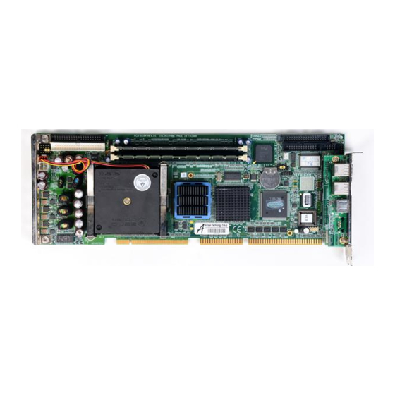
Chapter 1 Hardware Configuration 1.1 Introduction The PCA-6184 Series all-in-one industrial grade single board computer is a high performance and full-featured computing engine. It meets most industrial application requirements. Advantech's PCA-6184 full-sized CPU card is designed with Intel 845E/ 845 chipset and supports socket 478 Pentium® 4/Celeron® processor (FSB 533/400MHz) up to 2.4 GHz and above. -
Page 11: Table 1.1:Pca-6184 Series Comparison Table
Table 1.1: PCA-6184 series comparison table Model PCA-6184V- PCA- PCA- PCA-6184VE- 00A1 6184V- 6184VE- 00A2 00A2 00A1 CPU : Single Intel ® Pentium® 4/Celeron Socket 478 processor Chipset 845E 845E Front Side Bus 400MHz 533/ 400MHz 533/400MHz 400MHz USB Port... -
Page 12: Features
CPU fan, CPU temperature and system voltages levels are moni- tored to ensure stable operation, proper system configuration and management. A remote monitoring interface is reserved for remote management through Ethernet by using Advantech's SNMP-1000 system management module. ATX soft power switch: Through the BIOS, the power button can be defined as the "Standby"... -
Page 13: Specifications
• ISA driver current: Up to 64 mA high driving current • USB: Maximum up to four USB 1.1 ports. Four USB ports are avail- able in PCA-6184E2-00A1. • AC-97 Audio: PCA-6184 can provide audio function. (Require the optional audio extension module PCA-AUDIO-00A1; only for Ver. -
Page 14: Vga Interface
• Power supply voltage: +5 V, ±12 V • Power consumption: Typical: +5V @7.4A, +12V @320mA (Pentium 4 1.8GHz, 256MB DDR) • Board size: 338 x 122 mm (13.3" x 4.8") • Board weight: 0.5 kg (1.2 lb) PCA-6184 User’s Manual... -
Page 15: Jumpers And Connectors
1.4 Jumpers and Connectors Connectors on the PCA-6184 board link it to external devices such as hard disk drives and a keyboard. In addition, the board has a number of jumpers used to configure your system for your application. The tables below list the function of each of the board jumpers and con- nectors. - Page 16 Extension I/O board connector CN29 SM BUS Connector CN31 USB 0,1 CN32 USB 2,3 CN33 PS/2 Keyboard and Mouse connector CN34 10/100Base-T Ethernet connector 2 CN43 AC-97 Audio extension interface (only for Ver. A2) CN46 Auxiliary 4-pin power connector PCA-6184 User’s Manual...
-
Page 17: Board Layout: Jumper And Connector Locations
1.5 Board Layout: Jumper and Connector Locations Figure 1.1: Jumper and connecter locations... -
Page 18: Figure 1.2:Extension I/O Daughter Board
0, 1 Figure 1.2: Extension I/O daughter board PCA-6184 User’s Manual... -
Page 19: Safety Precautions
1.6 Safety Precautions Warning! Always completely disconnect the power cord from your chassis whenever you work with the hardware. Do not make connections while the power is on. Sensitive electronic components can be damaged by sudden power surges. Only experienced electronics personnel should open the PC chassis. -
Page 20: Cmos Clear (J1)
* default setting 1.7.3 Watchdog timer output (J2) The PCA-6184 contains a watchdog timer that will reset the CPU or send a signal to IRQ11 in the event the CPU stops processing. This feature means the PCA-6184 will recover from a software failure or an EMI problem. -
Page 21: System Memory
SDRAM. DIMMs are available in capacities of 64,128, 256, 512 MB and 1 GB. The sockets can be filled in any combination with DIMMs of any size, giving your PCA-6184 single board computer up to 2 GB of mem- ory. -
Page 22: Cpu Installation
1.11 CPU Installation The PCA-6184 provides socket 478 for an Pentium® 4 or Celeron® pro- cessor. The CPU on the board must have a fan or heat sink attached, to prevent overheating. Without a fan or heat sink, the CPU will over-... - Page 23 Connecting Peripherals This chapter tells how to connect peripherals, switches, and indicators to the PCA-6184 board.
-
Page 24: Chapter 2 Connecting Peripherals
You can attach up to four IDE (Integrated Drive Electronics) drives to the PCA-6184’s built-in controller. The primary (CN1) and secondary (CN2) connectors can each accommodate two drives. Wire number 1 on the cable is red or blue and the other wires are gray. -
Page 25: Floppy Drive Connector (Cn3)
2.2 Floppy Drive Connector (CN3) You can attach up to two floppy disk drives to the PCA-6184's onboard connector. You can use 3.5" (720 KB, 1.44 MB) drives. The card comes with a 34-pin daisy-chain drive connector cable. On one end of the cable is a 34-pin flat-cable connector. -
Page 26: Usb Ports (Cn6)
The USB interface can be disabled in the system BIOS setup. 2.5 VGA Connector (CN7) The PCA-6184 includes a VGA interface that can drive conventional CRT displays. CN7 is a standard 15-pin D-SUB connector commonly used for VGA. Pin assignments for CRT connector CN7 are detailed in Appendix B. -
Page 27: 10/100Base-T Ethernet Connectors (Cn8 And Cn34)
2.7 Serial Ports (CN9: COM1; CN10: COM2) CN9 and CN10 The PCA-6184 offers two serial ports, CN9 as COM1 and CN10 as COM2. These ports can connect to serial devices, such as a mouse or a printer, or to a communications network. -
Page 28: Ps/2 Keyboard And Mouse Connectors (Cn11 And 33)
PS/2 mouse connector. 2.9 External Keyboard Connector (CN12) CN12 In addition to the PS/2 mouse/keyboard connector on the PCA-6184's ear plate, there is also an extra onboard external keyboard connector. This gives system integrators greater flexibility in designing their systems. -
Page 29: Infrared (Ir) Connector (Cn13)
2.10 Infrared (IR) Connector (CN13) This connector supports the optional wireless infrared transmitting and receiving module. This module mounts on the system case. You must configure the setting through the BIOS setup (see Chapter 3). CN13 2.11 CPU Fan Connector (CN14) CN14 This connector supports cooling fans of with current up to 2A. -
Page 30: Front Panel Connectors (Cn16, 17, 18, 19, 21&22)
2.12 Front Panel Connectors (CN16, 17, 18, 19, 21&22) There are several external switches to monitor and control the PCA-6184. 2.12.1 Power LED and Keyboard Lock(CN16) CN16 is a 5-pin connector for the power on LED and Keyboard Lock. Users can also identify the current power mode through the system's power LED. -
Page 31: Reset (Cn18)
You can connect an LED to connector CN19 to indicate when the HDD is active. 2.12.5 SM Bus Connector (CN29) This connector is reserved for Advantech's SNMP-1000 HTTP/SNMP Remote System Manager. The SNMP-1000 allows users to monitor the internal voltages, temperature and fans from a remote computer through an Ethernet network. -
Page 32: Atx Power Control Connectors (Cn20 And 21)
CN20 2.13.1 ATX feature (CN20) and soft power switch (CN21) The PCA-6184 can support an advanced soft power switch function if an ATX power supply is used. To enable the soft power switch function: Connect the 3-pin plug of the cable to CN20 (ATX feature connec- tor). - Page 33 Award BIOS Setup This chapter describes how to set the card’s BIOS configuration data.
-
Page 34: Chapter 3 Award Bios Setup
CPU’s system status is valid. After ensuring that you have a number assigned to the patch code, press <Del> to allow you to enter the setup. Figure 3.1: Award BIOS Setup initial screen PCA-6184 User’s Manual... -
Page 35: Standard Cmos Setup
3.3 Standard CMOS Setup Choose the “Standard CMOS Features” option from the “Initial Setup Screen” menu, and the screen below will be displayed. This menu allows users to configure system components such as date, time, hard disk drive, floppy drive, display, and memory. Figure 3.2: Standard CMOS features screen 3.3.1 CMOS RAM backup The CMOS RAM is powered by an onboard button cell battery. -
Page 36: Advanced Bios Features
The “Advanced BIOS Features” screen appears when choosing the “Advanced BIOS Features” item from the “Initial Setup Screen” menu. It allows the user to configure the PCA-6184 according to his particular requirements. Below are some major items that are provided in the Advanced BIOS Features screen. -
Page 37: Swap Floppy Drive
3.4.5 Swap Floppy Drive Logical name assignments of floppy drives can be swapped if there is more than one floppy drive. The commands are “Enabled” or “Disabled.” 3.4.6 Boot UP Floppy Seek Selection of the command “Disabled” will speed the boot up. Selection of “Enabled”... -
Page 38: Advanced Chipset Features
3.5 Advanced Chipset Features By choosing the “Advanced Chipset Features” option from the “Initial Setup Screen” menu, the screen below will be displayed. This sample screen contains the manufacturer’s default values for the PCA-6184, as shown in Figure 3-4: Note:... -
Page 39: Dram Timing Selectable
3.5.1 DRAM Timing Selectable This item allows you to control the DRAM speed. The Choice: Host- Clock, CLK-33M. 3.5.2 CAS Letency Time This controls the latency between DDR RAM read command and the time that the data actually becomes available. Leave this on the default setting. -
Page 40: Video Bios Cacheable
Select the size of Accelerated Graphics Port (AGP) aperture. The aper- ture is a portion of the PCI memory address range dedicated for graphics memory address space. Host cycles that hit the aperture range are for- warded to the AGP without any translation. PCA-6184 User’s Manual... -
Page 41: Integrated Peripherals
3.6 Integrated Peripherals Figure 3.5: Integrated peripherals (1) 3.6.1 On-Chip Primary/Secondary PCI IDE If you enable IDE HDD Block Mode, the enhanced IDE driver will be enabled. Leave IDE HDD Block Mode on the default setting. 3.6.2 IDE 1st/2nd Mstr/Slave PIO/UDMA Modes (Auto) Each channel (Primary and Secondary) has both a master and a slave, making four IDE devices possible. -
Page 42: Onboard Serial Port 1 (3F8H/Irq4)
This item allows you to select UART mode. The choices: IrDA, ASKIR, Normal 3.6.9 RxD, TxD Active This item allows you to determine the active of RxD, TxD. The Choices: ìHi, Hi,î ìLo, Lo,î ìLo, Hi,î ìHi, Lo.. Figure 3.6: Integrated peripherals (2) 3.6.10 Onboard Parallel Port (378/IRQ7) PCA-6184 User’s Manual... -
Page 43: Parallel Port Mode (Ecp + Epp)
This field sets the address of the on-board parallel port connector. You can select either 3BC/IRQ7, 378/IRQ7, 278/IRQ5 or Disabled. If you install an I/O card with a parallel port, make sure there is no conflict in the address assignments. The CPU card can support up to three parallel ports, as long as there are no conflicts for each port. -
Page 44: Power Management
“Delay 4 sec.” If you do so, then pushing the button for more than 4 seconds will turn off the system, whereas pushing the button momentarily (for less than 4 seconds) will switch the system to “suspend” mode. PCA-6184 User’s Manual... -
Page 45: Cpu Thrm-Throttling
3.7.6 CPU THRM-Throttling This field allows you to select the CPU THRM-Throttling rate. The choices: 12.5%, 25.0%, 37.5%, 50.0%, 62.5%, 75.0%, 87.5%. 3.7.7 Power on by LAN This item allows you to wake up the system via LAN from the remote- host. -
Page 46: Reset Configuration Data
3.9.1 CPU Warning Temperature This item will prevent the CPU from overheating. The choices: 30~120. 3.9.2 Current System Temperature This shows you the current system temperature 3.9.3 Current CPU Temperature This shows you the current CPU speed. 3.9.4 VCORE PCA-6184 User’s Manual... -
Page 47: 12V/-5V/-12V
This shows CPU core voltage. 3.9.5 +5V/+12V/-5V/-12V This shows you the voltage of +5V/+12V/-5V/-12V 3.10 Load Setup Defaults “LOAD SETUP DEFAULTS” loads the default BIOS settings required by the system for reliable operation. 3.11 Password Setting To change the password: Choose the “Set Password”... -
Page 48: Save & Exit Setup
This record is required for the system to operate. 3.13 Exit Without Saving Selecting this option and pressing <Enter> lets you exit the setup program without recording any new values or changing old ones. PCA-6184 User’s Manual... - Page 49 Chipset Software Installation Utility This utility software installs to the Win- dows INF files that outline to the oper- ating system how the componentswill be configured. This utility has to be installed before other drivers. Chapter 4...
-
Page 50: Chapter 4 Chipset Software Installation Utility
To facilitate the installation of the enhanced display device drivers and utility software, you should read the instructions in this chapter carefully before you attempt installation. The device drivers for the PCA-6184 board are located on the software installation CD. The auto-run function of the driver CD will guide and link you to the utilities and device drivers under a Windows system. -
Page 51: Introduction
4.2 Introduction The Intel® Chipset Software Installation (CSI) utility installs to the target system the Windows INF files that outline to the operating system how the chipset components will be configured. This is needed for the proper functioning of the following features: •... -
Page 52: Installing The Csi Utility
Move the mouse cursor over the "Auto" button under the "CSI UTILITY" heading, a message pops up telling you to install the CSI utility before other device drivers, as shown in the following figure. Click on this button. PCA-6184 User’s Manual... - Page 53 Click "Next" when you see the following message Click "Yes" when you see the following message Chapter 4...
- Page 54 Click "Next" when you see the following message When the following message appears, click "Finish" to complete the installation and restart Windows PCA-6184 User’s Manual...
- Page 55 AGP SVGA Setup The PCA-6184 features an onboard VGA interface. This chapter provides instructions for installing and operating the software drivers on the display driver CD included in your package. Chapter 5...
-
Page 56: Chapter 5 Agp Svga Setup
The enhanced display drivers for the PCA-6184 board are located on the software installation CD. You must install the drivers and utility software by using the supplied SETUP pro- gram for DOS drivers.. -
Page 57: Features
5.2 Features • Built-in ATI RAGE 128 PRO 4XL multimedia accelerator • Supports AGP 4X mode with sideband addressing and AGP texturing • Superior 3D performance achieved through a floating point setup engine rated at 1.5 million triangles/sec • Integrated 250 MHz DAC allows 85 Hz refresh at 1600 x 1200 resolu- tion •... - Page 58 In the Setup, click on "next." In the Installation Information, choose turbo mode or standard. Then click on "Next." PCA-6184 User’s Manual...
- Page 59 The installaion is complete click on "Yes" to restart the system. Chapter 5...
- Page 60 PCA-6184 User’s Manual...
- Page 61 LAN Configuration The PCA-6184 features onboard dual 10/100Base-T Ethernet LAN. This chapter gives detailed information on Ethernet configuration. It shows you how to configure the card to match your application requirements Chapter 6...
-
Page 62: Chapter 6 Lan Configuration
Chapter 6 LAN Configuration 6.1 Introduction The PCA-6184 features single or dual 32-bit 10/100 Mbps Ethernet net- work interface. This interface supports bus mastering architecture and auto-negotiation features. Therefore standard twisted-pair cabling with RJ-45 connectors for both 10 Mbps, 100 Mbps connections can be used. -
Page 63: Windows Nt Drivers (Intel 82559) Setup Procedure
6.4 Windows NT Drivers (Intel 82559) Setup Procedure Note : The CD-ROM drive is designated as "D" throughout In the "Windows NT" screen, click on "Start" and select "Set- tings". Then click on the "Control Panel" icon to select "Network". Chapter 6... - Page 64 In the "Network" window, select the "Start Search" tab. Then click on "Next". In the "Select Network Adapter" window, click on "Have Disk...". PCA-6184 User’s Manual...
- Page 65 When the "Insert Disk" window appears, insert the utility CD into the CD-ROM drive. The correct file path is D:\Drv_Lan\82559. When you have the correct file path, click on "OK". In the "Network" window, select the "Adapters" tab. Under "Net- work Adapters:", highlight "Intel®...
- Page 66 In the "Microsoft TCP/IP Properties" window, select the "IP Address" tab. Then select "Specify an IP address". Type in the IP Address and Subnet Mask details. Then click on "OK". In the "Network Settings Change" window, click on "Yes" to restart the computer. PCA-6184 User’s Manual...
-
Page 67: Windows 2000 Drivers (Intel 82559) Setup Procedure
6.5 Windows 2000 Drivers (Intel 82559) Setup Proce- dure Note: The CD-ROM drive is designed as "D" through- out this section. In the "Windows 2000" screen, click on " Start" and select " set- tings". Then click on the " Control Panel" icon to select "system". In the "... - Page 68 In " Device Manager" screen, click on "Intel® PRO/100+ Server Adapter (PILA84708) #2. Then click on mice's right button. You can see "Property". Click on "Property".. In the following screen, to click on "Update Driver". Click on "Next". PCA-6184 User’s Manual...
- Page 69 Following the highlighted item, and click on "Next". Click on "Have Disk". Key in "D:\Drv_Lan\D_82559", then click on "OK". Chapter 6...
- Page 70 To highlight the following item, and click "Next". Click "Next". Click on "Yes" PCA-6184 User’s Manual...
- Page 71 Click "Finish" to complete the installation. Chapter 6...
- Page 72 PCA-6184 User’s Manual...
- Page 73 Onboard Security Setup This chapter explains OBS concepts and provides instructions for installing the relevant software drivers. This is done using the driver CD included in your PCA-6184 Chapter 7...
-
Page 74: Chapter 7 Onboard Security Setup
Onboard security (OBS) functions monitor key hardware. They help you maintain your system's stability and durability. The PCA-6184 can monitor 5 sets of system positive voltages, 2 sets of system negative voltages, CPU cooling fan speed, and CPU temperature. The positive system voltage sets which can be monitored include: •... - Page 75 When you will see the following message, make sure you have closed all other programs, then click on "OK." Click on the square graphics button when you see the following message. Chapter 7...
-
Page 76: Windows Nt Drivers Setup Procedure
7.3 Windows NT Drivers Setup Procedure Insert the driver CD into your system's CD-ROM drive. In a few seconds, the software installation main menu appears, as shown in the following figure. Click on the "WIN NT" button under the "OBS DRIVERS" heading. PCA-6184 User’s Manual... - Page 77 Click "Next" when you see the following message. Click "Next" when you see the following message. Chapter 7...
- Page 78 Click "Next" when you see the following message. Click "Finish" when you see the following message. PCA-6184 User’s Manual...
-
Page 79: Using The Obs Hardware Doctor Utility
Click "OK" to restart Windows. 7.4 Using the OBS Hardware Doctor Utility After completing the setup, all the OBS functions are permanently enabled. When a monitored reading exceeds safe limits, a warning mes- sage will be displayed and an error beep tone will activate to attract your attention. - Page 80 "OBS Hardware Doctor." It is recommended that you load the default values for all the OBS settings. However, if desired, you can establish new conditions for voltage, fan speed, and temperature. Please adjust TRANS_VCC high limit to 1.9V. . PCA-6184 User’s Manual...
- Page 81 Ultra ATA Storage Driver Setup This driver must be installed to use the Intel® Ultra ATA controller to improve storage subsystem performance and overall systemperformance. Chapter 8...
-
Page 82: Chapter 8 Ultra Ata Storage Driver Setup
PIO-only for both devices. • Technical details of the ATA subsystem can be viewed via use of the application. • Drivers are optimized. PCA-6184 User’s Manual... -
Page 83: Installation
8.3 Installation Note: Before installing this driver, make sure the CSI utility has been installed in your system. See Chapter 4 for information on installing the CSI utility. Insert the driver CD into your system's CD-ROM drive. In a few seconds, the software installation main menu appears, as shown in the following figure. - Page 84 Click on "Next" when you see the following message When you see the following message, click on "Yes" to accept the License Agreement. PCA-6184 User’s Manual...
- Page 85 Click on "Next" when you see the following message. Click on "Next" when you see the following message. Chapter 8...
- Page 86 When the following message appears, click "Finish" to complete the installation and restart Windows. PCA-6184 User’s Manual...
-
Page 87: Displaying Driver Information
8.4 Displaying Driver Information From the desktop of Windows, click on "Start" and select "Pro- grams." Then select "Intel Ultra ATA Storage Driver" and then "Companion." Click on the "Device Parameters" or the "Storage Report" tab to view related information. Chapter 8... - Page 88 PCA-6184 User’s Manual...
- Page 89 Programming the Watchdog Timer The PCA-6184 is equipped with a watchdog timer that resets the CPU or generates an interrupt if processing comes to a standstill for any reason. This feature ensures system reliability in industrial standalone or unmanned environments.
-
Page 90: Appendix A Programming The Watchdog Timer
Appendix A Programming the watchdog timer A.1 Programming the Watchdog Timer The PCA-6184's watchdog timer can be used to monitor system software operation and take corrective action if the software fails to function after the programmed period. This section describes the operation of the watchdog timer and how to program it. - Page 91 Unlock W83627H Select register of watchdog timer Enable the function of the watchdog timer Use the function of the watchdog time Lock W83627HF Appendix A...
-
Page 92: Table A.1:Watchdog Timer Registers
F5 (hex). This number decides how long the watchdog timer waits for strobe before generating an interrupt or reset signal. Writing a new value to this register can reset the timer to count with the new value. PCA-6184 User’s Manual... -
Page 93: Example Program
F7 (hex) read/write Bit 6: Write 1 to enable keyboard to reset the timer, 0 to dis- able.[default] Bit 5: Write 1 to gener- ate a timeout signal immediately and auto- matically return to 0. [default=0] Bit 4: Read status of watchdog timer, 1 means timer is ""time out""."... - Page 94 Enable watchdog timer and set 5 minutes as timeout interval ;----------------------------------------------------------- Mov dx,2eh ; unlock W83627H Mov al,87h Out dx,al Out dx,al ;----------------------------------------------------------- Mov al,07h ; Select registers of watchdog timer Out dx,al Mov al,08h Out dx,al PCA-6184 User’s Manual...
- Page 95 ;----------------------------------------------------------- Dec dx ; Enable the function of watchdog timer Mov al,30h Out dx,al Mov al,01h Out dx,al ;----------------------------------------------------------- Dec dx ; Set minute as counting unit Mov al,0f5h Out dx,al al,dx Or al,08h Out dx,al ;----------------------------------------------------------- Dec dx ; Set timeout interval as 5 minutes and start counting Mov al,0f6h Out dx,al Mov al,5...
- Page 96 Mov al,0f7h Out dx,al al,dx Or al,80h Out dx,al ;----------------------------------------------------------- Dec dx ; lock W83627HF Mov al,0aah Out dx,al Enable watchdog timer to be reset by keyboard ;----------------------------------------------------------- Mov dx,2eh ; unlock W83627H Mov al,87h Out dx,al PCA-6184 User’s Manual...
- Page 97 Out dx,al ;----------------------------------------------------------- Mov al,07h ; Select registers of watchdog timer Out dx,al Mov al,08h Out dx,al ;----------------------------------------------------------- Dec dx ; Enable the function of watchdog timer Mov al,30h Out dx,al Mov al,01h Out dx,al ;----------------------------------------------------------- Dec dx ; Enable watchdog timer to be strobed reset by keyboard Mov al,0f7h Out dx,al al,dx...
- Page 98 Out dx,al ;----------------------------------------------------------- Dec dx ; Generate a time-out signal Mov al,0f7h Out dx,al ;Write 1 to bit 5 of F7 register al,dx Or al,20h Out dx,al ;----------------------------------------------------------- Dec dx ; lock W83627HF Mov al,0aah Out dx,al PCA-6184 User’s Manual...
- Page 99 I/O Pin Assignments This appendix contains information of a detailed or specialized nature. It includes: • IDE Hard Drive Connector • Floppy Drive Connector • Parallel Port Connector • USB Connector • VGA Connector • Ethernet 10/100Base-T RJ-45 Connector • COM1/COM2 RS-232 Serial Port •...
-
Page 100: Appendix B Pin Assignments
DATA 0 DATA 15 SIGNAL GND DISK DMA Request IO Write IO READ IO CHANNEL READY HDACKO* IRQ14 ADDR 1 ADDR 0 ADDR 2 HARD DISK SELECT 0* HARD DISK SELECT 1* IDE ACTIVE * low active PCA-6184 User’s Manual... -
Page 101: Floppy Drive Connector (Cn3)
B.2 Floppy Drive Connector (CN3) Table B.2: Floppy Drive Connector (CN3) Signal Signal FDHDIN DATA 6 FDEDIN INDEX* MOTOR 0* DRIVE SELECT1* DRIVE SELECT 0* MOTOR 1* DIRECTION* STEP* WRITE DATA* WRITE GATE* TRACK 0* WRITE PROTECT* READ DATA* HEAD SELECT* DISK CHANGE * low active Appendix B... -
Page 102: Parallel Port Connector (Cn4)
B.3 Parallel Port Connector (CN4) Table B.3: Parallel Port Connector (CN4) Signal Signal STROBE* AUTOFD* INIT* SLCTINI* ACK* BUSY SLCT * low active PCA-6184 User’s Manual... -
Page 103: Usb Connector (Cn6)
B.4 USB Connector (CN6) Table B.4: USB Connector (CN6) USB1 Signal USB2 Signal +5 V +5 V UNV- Chassis GND B.5 VGA Connector (CN7) Table B.5: VGA Connector (CN7) Signal Signal GREEN BLUE V-SYNC Appendix B... -
Page 104: Ethernet Base-T Connector (Cn8, Cn34)
B.6 Ethernet Base-T Connector (CN8, CN34) Table B.6: Ethernet 10/100Base-T RJ-45 Connector (CN8, CN34) Signal Signal XMT+ XMT- RCV- RCV+ B.7 COM1/COM2 Serial Port (CN9, CN10) Table B.7: COM1/COM2 RS-232 serial port (CN9, CN10) Signal PCA-6184 User’s Manual... -
Page 105: Keyboard And Mouse Connnector (Cn11)
B.8 Keyboard and Mouse Connnector (CN11) Table B.8: Keyboard and Mouse Connector (CN 11) Signal KB DATA MS DATA KB CLOCK MS CLOCK B.9 External Keyboard Connector (CN12) Table B.9: External Keyboard Connector (CN 12) Signal DATA Appendix B... -
Page 106: Ir Connector (Cn13)
B.10 IR Connector (CN13) Table B.10: IR Connector (CN 13) Signal +5 V IR_RX IR_TX B.11 CPU Fan Power Connector (CN14) Table B.11: CPU Fan Power Connector (CN 14) Signal +12 V Detect PCA-6184 User’s Manual... -
Page 107: Power Led And Keyboard Lock (Cn16)
B.12 Power LED and Keyboard Lock (CN16) You can use an LED to indicate when the CPU card is on. Pin 1 of CN16 supplies the LED's power, and Pin 3 is the ground. Pin 4 is for keyboard lock. Table B.12: Power LED and Keyboard Lock (CN 16) Function LED power (+5 V) -
Page 108: Reset Connector (Cn18)
B.14 Reset Connector (CN18) Table B.14: Reset Connector (CN 18) Signal Reset B.15 HDD LED Connector (CN19) Table B.15: HDD LED Connector (CN 19) Signal Vcc(LED+) LED0 (LED-) PCA-6184 User’s Manual... -
Page 109: Atx Feature Connector (Cn20)
B.16 ATX Feature Connector (CN20) Table B.16: ATX Feature Connector (CN 20) Signal PS-ON VCC5VSB B.17 ATX Soft Power Switch (CN21) Table B.17: ATX soft power switch (CN21) Signal 5VSB PWR-BTN Appendix B... -
Page 110: Audio Interface (Cn43)
D- (USB1) D+ (USB2) D- (USB0) D- (USB3) Vcc (USB1) D- (USB2) Vcc (USB0) Vcc (USB3) GND (USB1) Vcc (USB2) GND (USB0) GND (USB3) 5VSB GND (USB2) ACT LED (LAN2) D+ (USB1) LINK (LAN 2) D+ (USB0) SPEED-100Mbps PCA-6184 User’s Manual... -
Page 111: Extension I/O Board Connector (Cn28)
B.20 Extension I/O Board Connector (CN28) Table B.20: Extension I/O Board Connector (CN 28) Signal Signal TXC+ (DVI) TX0+ (DVI) TXC- (DVI) TX0- (DVI) FP_SDAT (DVI) TXD+ (LAN2) FP_SCLK (DVI) H_DEC (DVI) RXIN+ (LAN2) FP_VCC (DVI) TXD- (LAN2) TX2+ (DVI) MS DATA (PS/2 MS) TX2- (DVI) RXIN- (LAN2) -
Page 112: Sm Bus Connector (Cn29)
System speaker 062~063 Motherboard resources 064~064 Standard 101/102 key or Microsoft Natural PS/2 065~06F Motherboard resources 070~073 System CMOS/real time clock 074~07F Motherboard resources 080~090 Direct memory access controller 091~093 Motherboard resources 094~09F Direct memory access controller PCA-6184 User’s Manual... -
Page 113: Dma Channel Assignments
Table B.22: System I/O Ports Address Range Device (HEX) 0A0~0A1 Programmable interrupt controller 0A2~0BF Motherboard resources 0C0~0DF Direct memory access controller 0E0~0EF Motherboard resources 0F0~0FF Numeric data processor 170~177 Secondary IDE channel 1F0~1F7 Primary IDE channel 279~279 ISAPNP read data port 294~297 Motherboard resources 3F8 ~ 3FF... -
Page 114: B.24 Interrupt Assignments
Addr. range (HEX) Device F0000h - FFFFFh System ROM CC000h - EFFFFh Unused C0000h - CBFFFh VGA BIOS B8000h - BFFFFh CGA/EGA/VGA text B0000h - B7FFFh Unused A0000h - AFFFFh EGA/VGA graphics 00000h - 9FFFFh6 Base memory PCA-6184 User’s Manual... -
Page 115: B.26 Pci Bus Map
B.26 PCI Bus Map Table B.26: PCI bus map Function Device_ID INT# Pin GNT# Pin Onboard LAN1 AD21 INTG GNTE Onboard LAN2 AD20 INTH GNTA ISA Bridge AD22 GNTF PCI slot 1 AD31 INT B, C, D, A GNTA PCI slot 2 AD30 INT C, D, A, B GNTB... - Page 116 PCA-6184 User’s Manual...
Need help?
Do you have a question about the PCA-6184 and is the answer not in the manual?
Questions and answers