
Related Manuals for Advantech PCA-6145B


Summary of Contents for Advantech PCA-6145B
- Page 1 PCA-6145B Half-size 486 All-in-one CPU Card with Panel/CRT and Ethernet Interface PCA-6145L Half-size 486 All-in-one CPU Card with Panel/CRT Interface...
-
Page 2: Copyright Notice
Copyright Notice This document is copyrighted, 1997, by Advantech Co., Ltd. All rights are reserved. Advantech Co., Ltd., reserves the right to make improvements to the products described in this manual at any time without notice. No part of this manual may be reproduced, copied, translated, or transmitted in any form or by any means without the prior written permission of Advantech Co., Ltd. -
Page 3: Technical Support
Our dealers are trained and ready to give you the support you need to get the most from your Advantech products. In fact, most problems reported are minor and are able to be easily solved over the phone. -
Page 4: Product Warranty
Product warranty Advantech warrants to you, the original purchaser, that each of its products will be free from defects in materials and workmanship for one year from the date of purchase. This warranty does not apply to any products which have been... -
Page 5: Packing List
Before you begin installing your card, please make sure that the following materials have been shipped: • 1 PCA-6145B/6145L CPU card • 1 6-pin mini-DIN keyboard & PS/2 mouse adapter • 1 Hard disk drive (IDE) interface cable (40 pin) •... -
Page 6: Table Of Contents
Contents Chapter 1 Hardware Configuration ......1 Introduction ................2 Specifications ................2 Board layout ................5 Jumpers settings ..............8 Jumper settings ............... 8 How to set jumpers ............... 8 CPU type select ..............9 Watchdog timer (JP29) ............12 COM2 setting for RS-232/422/485 (JP35~39) .... - Page 7 Entering setup ..............24 Standard CMOS setup ............25 BIOS features setup ............26 CHIPSET features setup ............. 30 Power management setup ........... 31 Load BIOS defaults ............32 Load setup defaults ............. 32 Password setting ..............32 IDE HDD auto detection ............. 32 Save &...
- Page 8 Appendix A Programming the Watchdog Timer ..55 Appendix B Upgrading ..........57 Installing PC/104 module (CN5, CN6) ....... 58 Installing DRAM (SIMMs) ..........60 Appendix C Detailed System Information ....61 Appendix D POST LEDs .......... 71...
-
Page 9: Chapter 1 Hardware Configuration
Hardware Configuration This chapter gives background informa- tion on the PCA-6145B/6145L. It then shows you how to configure the card to match your application and prepare it for installation into your PC. Sections include: • Card specifications • Board layout •... -
Page 10: Introduction
Introduction The PCA-6145B/6145L is a full-function CPU card which integrates the VGA LCD panel, Ethernet and other enhanced I/O interfaces on a half- size CPU card. This card uses a 80486 DX, DX2, DX4 CPU or 5x86 series and can have up to 32 MB DRAM and EDO RAM. It also provides an optional 128 KB cache RAM. - Page 11 • I/O bus expansion: PC/104 connector with face-up installation • SSD: Supports M-systems DiskOnChip flash disk • Flash Backup: CMOS Data Ethernet controller functions (PCA-6145B only) • Controller: UMC UM9008, built-in 8k x 16 SRAM • I/O address switchless setting •...
-
Page 12: Mechanical And Environmental
F (0 to 60 • Storage temperature: -40 to +176°F (-40 to +80 • Humidity: 5 to 95%, non-condensing • Board size: 7.3" (L) x 4.8" (W) (185 mm x 122 mm) • Board weight: 1.2 lb. (0.5 kg) PCA-6145B/6145L User's Manual... -
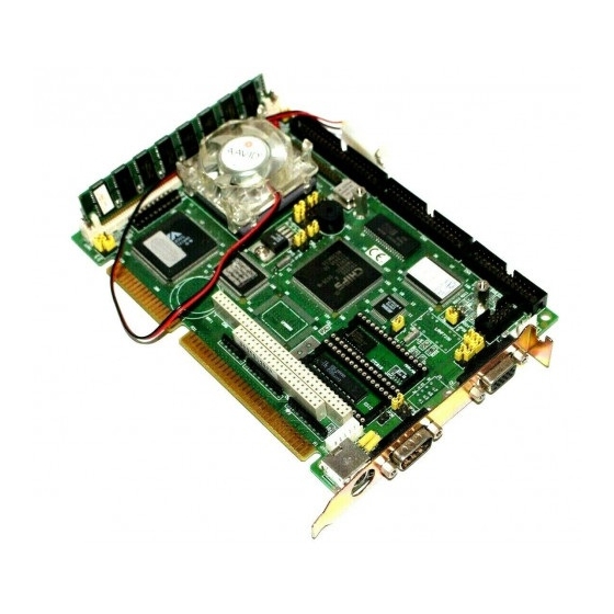
Page 13: Board Layout
Board layout PCA-6145B/PCA-6145L PCB Layout Chapter 1 Hardware Configuration... -
Page 14: Jumpers And Connectors
Battery backup JP11 CPU type select JP13 CPU type select JP14 Voltage selection JP15 PS/2 mouse set JP20, JP21 CPU type select JP22-JP24 S.S.D. Function set JP28 LCD Control JP29 Watchdog timer JP30 Rest switch JP35-JP39 COM2 select PCA-6145B/6145L User's Manual... -
Page 15: Safety Precautions
PCA-6145B/PCA-6145L Connectors Number Function Enhanced IDE connector LCD connector FDD connector Parallel port connector COM1 Serial port 1 connector COM2 Serial port 2 connector SBC power connector VGA connector Ethernet connector External Keyboard connector Keyboard connector Keyboard lock Speaker Safety precautions Follow these simple precautions to protect yourself from harm and your PC from damage. -
Page 16: Jumpers Settings
You may find pair of needle-nose pliers useful for setting the jumpers. If you have any doubts about the best hardware configuration for your application, contact your local distributor or sales representa- tive before you make any changes. PCA-6145B/6145L User's Manual... -
Page 17: Cpu Type Select
CPU type select In order for the system to function properly, the jumpers must be set to accommodate the CPU installed on the CPU card. CPU type select CPU Type JP4 JP5 JP6 JP7 JP8 JP11 JP13 JP14 JRN1 JRN2 JRN3 Intel DX-33(5V) DX2-66... - Page 18 CPU type select CPU Type JP4 JP5 JP6 JP7 JP8 JP11 JP13 JP14 JRN1 JRN2 JRN3 Cyrix 5x86-120 DX4-120 (3.3V)(SV8B) Intel P24D DX4-75 (5V) Cyrix DX2-66 DX2-66 (5V) TI DX2-66 (3.3V) PCA-6145B/6145L User's Manual...
- Page 19 CPU type select CPU Type JP4 JP5 JP6 JP7 JP8 JP11 JP13 JP14 JRN1 JRN2 JRN3 Cyrix DX2-80 TI DX2-80 (3.3V) DX-40 DX2-80(5V) DX4-100 (NV8T) (3.3 V) Note: 1. AMD 5X86-133 JP20 ON other OFF 2. AMD DX2-80 JP21 ON other OFF Default setting: Intel DX4-100 Chapter 1 Hardware Configuration...
-
Page 20: Watchdog Timer (Jp29)
1 2 3 1 2 3 JP35 JP36 JP37 JP38 3 2 1 3 2 1 3 2 1 JP39 6 5 4 6 5 4 6 5 4 Battery backup select Battery Backup (default) 1 2 3 PCA-6145B/6145L User's Manual... -
Page 21: Ps/2 Mouse Setting
PS/2 mouse setting PS2 Mouse (default) 1 2 3 JP15 LCD type control (default) 1 2 3 1 2 3 JP28 Chapter 1 Hardware Configuration... - Page 22 PCA-6145B/6145L User's Manual...
-
Page 23: Chapter 2 Connecting Peripherals
This chapter tells how to connect peripherals, switches and indicators to the PCA-6145B/PCA-6145L board. You can access most of the connectors from the top of the board while it is installed in the chassis. If you have a number of cards... - Page 24 The following table lists the connectors on the PCA-6145B/PCA- 6145L. Connectors Label Component IDE connector LCD connector FDD connector Parallel port connector CN5,CN6 PC 104 connector JP30 Reset Switch LED1 Power LED LED2 Ethernet LED The following sections tell how to make each connection. In most cases, you will simply need to connect a standard cable.
-
Page 25: Enhanced Ide Connectors (Cn1)
CN2 consists of a 44-pin, dual-in-line header. Power supplies (+12V) present on CN2 depend on the supply connected to the board. The PCA-6145B/PCA-6145L provides a bias control signal on CN2 which can be used to control the LCD bias voltage. It is recommended that the LCD bias voltage (+5V) and panel video signals are stable. -
Page 26: Floppy Drive Connector (Cn3)
Floppy drive connector (CN3) You can attach up to two floppy disk drives to the PCA-6145B/ PCA-6145L's on-board controller. You can use any combination of 5.25" (360 KB and 1.2 MB) and/or 3.5" (720 KB, 1.44 MB and 2.88 MB) drives. -
Page 27: Keyboard & Ps/2 Mouse Connectors (J5)
VGA interface. J2 is a DB-15 connector for VGA monitor input. Serial Ports The PCA-6145B/PCA-6145L offers two serial ports: COM1 in RS- 232, COM2 in RS-232/422/485. These ports let you connect to serial devices (a mouse, printers, etc.) or a communication network. -
Page 28: Rs-232 Connection (Com1)
If you are having problems with a serial device, be sure to check the pin assignments for the connector. The following table shows the pin assignments for the card's RS-232 port: RS-232 connector pin assignments Signal COM1 PCA-6145B/6145L User's Manual... -
Page 29: Rs-232/422/485 Connections (Com2)
RS-232/422/485 connection (COM2) COM2 is an RS-232/422/485 serial port. The specific port type is determined by jumper settings JP35 - JP39, as detailed in Chapter 1. The following table shows the pin assignments for COM2. RS-232/485 connector pin assignments RS-232 RS-422/485 TX - or send data - (DTE) TX + or send data + (DTE) -
Page 30: Power Connectors J1
Power connectors J1 If you prefer not to acquire power through PCA-6145B/PCA- 6145L's backplane via the gold H-connectors, J1 also provide power input connectors for +5 V and +12 V. Warning! Before making the connection, make sure the voltage is absolutely correct and matched with the right connector. -
Page 31: Chapter 3 Award Bios Setup
AWARD BIOS SETUP This chapter describes how to set the card’s BIOS configuration data. -
Page 32: Award Bios Setup
This type of informa- tion is stored in battery-backed RAM so that it retains the Setup information when the power is turned off. Entering setup Turning on the computer and pressing <DEL> immediately will allow you to enter Setup. PCA-6145B/6145L User's Manual... -
Page 33: Standard Cmos Setup
Standard CMOS setup Choose the "STANDARD CMOS SETUP" option from the INITIAL SETUP SCREEN Menu, and the screen below is dis- played. This standard Setup Menu allows users to configure system components such as date, time, hard disk drive, floppy drive, display, and memory. -
Page 34: Bios Features Setup
Type "Y" to accept write or "N" to abort write Award Software, Inc. You can run the anti-virus program to locate the problem. If Virus Warning is Disabled, no warning message will appear if anything attempts to access the boot sector or hard disk partition. PCA-6145B/6145L User's Manual... - Page 35 CPU Internal Cache/External Cache Depending on the CPU/chipset design, these options can speed up memory access when enabled. Quick Power On Self Test This option speeds up the Power-On Self Test (POST) conducted as soon as the computer is turned on. When enabled, BIOS shortens or skips some of the items during the test.
- Page 36 The input values (msec) for this category are: 250, 500, 750, 1000. Security Option This setting determines whether the system will boot if the password is denied, while limiting access to Setup. PCA-6145B/6145L User's Manual...
- Page 37 Note: To disable security, select PASSWORD SETTING in the main menu. At this point, you will be asked to enter a password. Simply hit the <ENTER> key to disable security. When security is disabled, the system will boot, and you can enter Setup freely. OS select for DRAM>64 MB.
-
Page 38: Chipset Features Setup
: Turbo Esc : Quit : Select Item Set Mouse clock : Disabled : Help PU/PD/+/- : Modify LAN Card Boot ROM : Disabled : Old Values (Shift)F2 : Color : Load BIOS Defaults : Load Setup Defaults PCA-6145B/6145L User's Manual... -
Page 39: Power Management Setup
Power management setup The power management setup controls the CPU board's "green" features. The following screen shows the manufacturer's default. ROM ISA BIOS (2C4L6AKK) CMOS SETUP UTILITY POWER MANAGEMENT SETUP Power Management : Disabled IRQ3 Activity : Primary Doze Timer : 32 sec IRQ4 Activity : Primary... -
Page 40: Load Bios Defaults
This record is required for the system to operate. Exit without saving Selecting this option and pressing the [Enter] key lets you exit the Setup program without recording any new values or changing old ones. PCA-6145B/6145L User's Manual... -
Page 41: Chapter 4 Vga Display & Ethernet Software/Hardware Configuration
VGA Display & Ethernet Software/Hardware Configuration This chapter details the software configu- ration information. It shows you how to configure the board to match your application requirements. AWARD System BIOS is covered in Chapter 4. Sections include: • LCD display configuration •... -
Page 42: Introduction
You can change the display BIOS simply by reprogramming the Flash chip. PCA-6145B/PCA-6145L Utility Disk The PCA-6145B/PCA-6145L is supplied with a software utility disk that holds the necessary file for setting up the VGA display and Ethernet and Win 95 controller. The disk’s directory and file... - Page 43 Configure the VGA display as follows: 1. Apply power to the PCA-6145B/PCA-6145L with a color TFT display attached. This is the default setting for the PCA-6145B/ PCA-6145L. Ensure that the AWDFLASH.EXE and *.BIN files are located in the working drive.
-
Page 44: Vga Win 95 Driver Support
This configuration will remain the same until you run the AWDFLASH.EXE program and change the settings. VGA Win 95 Driver Support These drivers are designed to work with Microsoft Windows 95. You may install these drivers through Windows 95. PCA-6145B/6145L User's Manual... -
Page 45: Ethernet Software Configuration
1. Power the PCA-6145B on. Ensure that the DIAG 9008.EXE file is located in the working drive. 2. At the prompt type DIAG 9008.EXE and press <Enter>. The Ethernet configuration program will then be displayed. -
Page 46: Ethernet Driver Support
Ethernet Driver Support These drivers are designed to work in a workstation environment under Windows NT, Win 95, or DOS operating system. You may install these drivers for your application. PCA-6145B/6145L User's Manual... -
Page 47: Chapter 5 Svga Setup
SVGA Setup The PCA-6145B/PCA-6145L features an on-board flat panel/VGA interface. This chapter provides instructions for install- ing and operating the software drivers on the included display driver diskette. -
Page 48: Simultaneous Display Mode
Both CRT and panel displays can be used simultaneously. The PCA-6145B/PCA-6145L can be set in one of three configurations: on a CRT, on a flat panel display, or on both simultaneously. The system is initially set to simultaneous display mode. In the utility diskette, there are three .COM files which can be used to select the... -
Page 49: Software Support
Software support The drivers support the following applications using the filenames and resolutions listed: Application Filename Resolution Colors Windows 3.1 LINEAR4.DRV 640x480 800x600 1024x768 LINEAR8.DRV 640x480 800x600 1024x768 LINEAR16.DRV 640x480 LINEAR24.DRV 640x480 AutoCAD R12 RCTURBOC.EXP 640x480 800x600 1024x768 640x480 800x600 1024x768 640x480 640x480... -
Page 50: Driver Installation
The display driver diskette contains drivers for several versions of certain applications. You must install the correct version in order for the driver to work properly so make sure you know which version of the application you have. PCA-6145B/6145L User's Manual... -
Page 51: Windows Setup
Windows setup These drivers are designed to work with Microsoft Windows 3.1. You may install these drivers through Windows or in DOS. Step 1: Install Windows as you normally would for a VGA display. Run Windows to make sure that it is working correctly. Step 2: Place the display driver diskette in drive A. -
Page 52: Dos Setup
Setup, repeating steps 4 and 5 from the previous page. Besides the special display drivers marked by an asterisk (*), you should be able to use the following standard drivers: 640x480, 16 colors Super VGA 800x600, 16 colors PCA-6145B/6145L User's Manual... - Page 53 Panning Drivers Special panning drivers are provided to allow high-resolution modes to be displayed on a flat panel or CRT. These drivers will show a section of a larger screen and will automatically pan, or scroll, the screen horizontally and vertically when the mouse reaches the edge of the display.
-
Page 54: Autocad R12
Select Configure Video Display. In Display Device Configuration choose Select Graphics Board/Resolution. Then choose Select Display Graphics Board. After choosing a graphics board, go to Select Display Resolution. After selecting the display resolution, save the new configuration, and return to the main menu. PCA-6145B/6145L User's Manual... - Page 55 Basic Configuration Menu This menu allows you to modify: Number of AutoCAD Command Lines Font Size 6x8/8x8/8x14/8x16/12x20/12x24 Dual Screen Enable/Disable User Interface Configuration Double Click Interval Time BP Button BP Highlight Patt Line/Xor Rect/Both BP Refresh Enable/Disable BP Cache Enable/Disable Expert Configuration Menu This menu allows you to modify: Display List...
-
Page 56: Lotus 1-2-3 And Lotus Symphony
Step 4: After the selection of the appropriate VGA display driver, you will need to exit this menu and return to the Main Lotus Installation Menu. Do this by selecting Return To Menu. Step 5: At the Main Lotus Installation Menu, select Save Chang- PCA-6145B/6145L User's Manual... - Page 57 Step 6: At this point the Installation Menu will prompt you for the name of your new Lotus configuration file. The Lotus system will prompt you with the default value — 123.SET, but you may want to use a filename that indicates the resolution of its driver. For example, if you installed the 132 column by 25 line driver, you could name this driver 132X25.SET, or if you installed the 80 by 50 driver, you may want to call the file 80X50.SET.
-
Page 58: Vesa
NOTE: If the video BIOS already supports VBE extended video modes, DO NOT use this driver. Run the VTEST.EXE program to see if the video BIOS supports the VBE modes. PCA-6145B/6145L User's Manual... -
Page 59: Word
Word These drivers are designed to work with Microsoft Word 5.0 and 5.5. Driver installation If you have already installed Word on your computer, go to Step 2 to install the new video driver. Step 1: Install Word as normal. Step 2: After you complete the Word installation, place the display driver diskette into drive A. -
Page 60: Wordperfect
Press <ESC> followed by Y to exit to DOS. Step 2: Start WordPerfect, and press <SHIFT>+<F1> to enter the setup menu. Select D for Display and G for Graphics Screen Type, and then choose the desired Chips VGA resolution. PCA-6145B/6145L User's Manual... - Page 61 Configuring WordPerfect 5.0 for 132 columns Follow these instructions to configure WordPerfect 5.0 for 132 column text mode: Step 1: To use the SETCOL program to set 132 columns and 25 rows, type the following command: SETCOL 132, 25 <ENTER> Step 2: Start WordPerfect.
- Page 62 PCA-6145B/6145L User's Manual...
-
Page 63: Appendix A Programming The Watchdog Timer
Programming the Watchdog Timer The PCA-6145B/PCA-6145L is equipped with a watchdog timer that resets the CPU or generates an interrupt if processing comes to a standstill for whatever reason. This feature ensures system reliability in industrial stand-alone and unmanned environments. -
Page 64: Programming The Watchdog Timer
REM Reset the timer Step your application program task #2 Step out 443h, data REM Reset the timer Step in 43h REM Disable watchdog function Date values 1 sec. 2 sec. 3 sec. 4 sec. 63 sec PCA-6145B/6145L User's Manual... -
Page 65: Appendix B Upgrading
Upgrading This appendix gives instructions for increasing the capabilities of your CPU card. It covers: • Installing PC/104 • DRAM memory installation (SIMMs) -
Page 66: Installing Pc/104 Module (Cn5, Cn6)
Installing PC/104 modules (CN5,CN6) The PCA-6145B/PCA-6145L card's PC/104 connector lets you attach PC/104 modules. These modules perform the functions of traditional plug-in expansion cards, but save space and valuable slots. Advantech modules include: • PCM-3110 PCMCIA module • PCM-3718 30 KHz A/D module •... - Page 67 PC/104 module dimensions (mm) Appendix B Upgrading...
-
Page 68: Installing Dram (Simms)
Installing DRAM (SIMMs) You can use anywhere from 1 MB to 32 MB of DRAM with your PCA-6145B/PCA-6145L. The card provides one 72-pin SIMM (single in-line memory module) socket that accepts from 1 to 32 MB DRAM or EDO RAM. The following table shows the bank... -
Page 69: Appendix C Detailed System Information
Detailed system information This appendix contains information of a detailed or specialized nature. It includes: • Parallel connector pin assignments • HDD connector pin assignments • FDD connector pin assignments • Keyboard connector pin assignments • CRT display connector • Flat panel display connector •... - Page 70 Parallel/printer connector (CN4) Pin no. Signal STROBE DATA 0 DATA 1 DATA 2 DATA 3 DATA 4 DATA 5 DATA 6 DATA 7 - ACKNOWLEDGE BUSY PAPER EMPTY + SELECT - AUTO FEED - ERROR - INIT PRINTER - SELECT INPUT 18-25 GROUND HDD connector (CN1)
- Page 71 Pin no. Signal Pin no. Signal IORDY BALE N.C. -IO CS16 N.C. -ACT FDD connector (CN3) Pin no. Signal 1-33 (odd) GROUND HIGH DENSITY 4, 6 UNUSED INDEX MOTOR ENABLE A DRIVER SELECT B DRIVER SELECT A MOTOR ENABLE B DIRECTION STEP PULSE WRITE DATA...
- Page 72 VGA display connector (J2) PCA-6145 CRT display connector Signal Signal GREEN BLUE H-SYNC V-SYNC Flat panel display connector (CN2) mini pin header PCA-6145 Flat panel display connector Function Function +12 V +12 V ENAVEE SHFCLK ENABKL KB-DATA KB-CLK PCA-6145/6145L User's Manual...
- Page 73 RS-232 connections (COM1, COM2) Different devices implement the RS-232 standard in different ways. If you are having problems with a serial device, be sure to check the pin assignments for the connector. The following table shows the pin assignments for the card's RS-232 port: RS-232 connector pin assignment Signal 5 4 3 2 1...
- Page 74 PC/104 Connector Pin Assignments IOCHCHK* 0V SBHE* MEMCS16* RESETDRV LA23 IOCS16* LA22 IRQ10 IRQ9 LA21 IRQ11 LA20 IRQ12 DRQ2 LA19 IRQ15 -12V LA18 IRQ14 OWS* LA17* DACK0* MEMR* DRQ0* IOCHRDY NC MEMW* DACK5* SMEMW* DRQ5 SA19 SMEMR* DACK6* SA18 IOW* SD10 DRQ6 SA17...
- Page 75 System I/O ports Addr. range (Hex) Device 000-01F DMA controller 020-021 Interrupt controller 1, master 022-023 Chipset address 040-05F 8254 timer Watchdog timer disable 060-06F 8042 (keyboard Controller) 070-07F Real-time clock, non-maskable interrupt (NMI) mask 080-09F DMA page register, 0A0-0BF Interrupt controller 2 0C0-0DF DMA controller...
- Page 76 System information I/O addresses Address Description 00-0D * Real-time clock information Second Second alarm Minutes Minute alarm Hours Hours alarm Day of week Date of month Month Year Status register A Status register B Status register C Status register D * Diagnostic status byte * Shutdown status byte Diskette drive type byte, drives A and B...
- Page 77 DMA channel assignments Channel Function Spare (8-bit transfer) SDLC (8-bit transfer) Floppy disk (8-bit transfer) Spare (8-bit transfer) Cascade for DMA controller 1 Spare (16-bit transfer) Spare (16-bit transfer) Spare (16-bit transfer) DMA controller registers Address Command code CH0 base and current address CH0 base and current word count CH1 base and current address CH1 base and current word count...
- Page 78 DMA Page Addresses Page register I/O Address DMA Channel 0 0087 DMA Channel 1 0083 DMA Channel 2 0081 DMA Channel 3 0082 DMA Channel 5 008B DMA Channel 6 0089 DMA Channel 7 008A Refresh 008F Interrupt assignments Priority Interrupt# Interrupt source Parity error detected...
-
Page 79: Appendix D Post Leds
POST LEDs This appendix lists the codes generated by the POST (Power On Self Test) routines. It also discusses how to read the PCA-6145B/PCA-6145L's POST LED indicators. - Page 80 You can also determine the number of the test that failed by reading the LED indicators on the top of the PCA-6145B/PCA- 6145L board. Please make a note of any POST error codes before you contact Advantech for technical support.
- Page 81 I/O address 80H. If the test fails, the code will stay in memory. You can read the code and determine which test has failed. The PCA-6145B/PCA-6145L’s POST LED indicators make this process extremely easy. You don’t need any special diagnostic tools, you just read the POST code from the LEDs.
- Page 82 Code Name Description of check-point PCA-6145B/6145L User's Manual...
- Page 83 Code Name Description of check-point Appendix D POST LEDs...
- Page 84 Code Name Description of check-point PCA-6145B/6145L User's Manual...
- Page 85 Code Name Description of check-point Appendix D POST LEDs...
- Page 86 PCA-6145B/6145L User's Manual...
Need help?
Do you have a question about the PCA-6145B and is the answer not in the manual?
Questions and answers