
Related Manuals for Advantech PCA-6010


Summary of Contents for Advantech PCA-6010
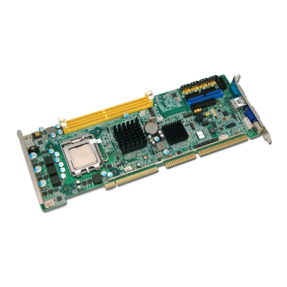
- Page 1 User Manual PCA-6010 ® PICMG 1.0 Full-sized Intel LGA775 processor Card with VGA / Single Gigabit LAN...
- Page 2 No part of this manual may be reproduced, copied, translated or transmitted in any form or by any means without the prior written permission of Advantech Co., Ltd. Information provided in this manual is intended to be accurate and reliable. How- ever, Advantech Co., Ltd.
- Page 3 Whether your new Advantech equipment is destined for the labo- ratory or the factory floor, you can be assured that your product will provide the reliability and ease of operation for which the name Advantech has come to be known.
- Page 4 SEC K4T51083QE ZCE6 (64x8) DDR2 667 DDR2 SEC K4T51083QG HCE6 (64x8) SAMSUNG K4T1G084QD-ZCE6 DDR2 667 DDR2 (128x8) DDR2 667 DDR2 Micron 7HE12 D9HNL (128x8) SAMSUNG K4T1G084QA-ZCE6 DDR2 667 DDR2 (128x8) Network Feature Comparison LAN/Model PCA-6010LV PCA-6010VG LAN1: Intel® 82574L PCA-6010 User Manual...
- Page 5 Because of Advantech’s high quality-control standards and rigorous testing, most of our customers never need to use our repair service. If an Advantech product is defec- tive, it will be repaired or replaced at no charge during the warranty period. For out- of-warranty repairs, you will be billed according to the cost of replacement materials, service time and freight.
- Page 6 It should be free of marks and scratches and in perfect working order upon receipt. As you unpack the PCA-6010, check it for signs of ship- ping damage. (For example, damaged box, scratches, dents, etc.) If it is damaged or it fails to meet the specifications, notify our service department or your local sales representative immediately.
-
Page 7: Table Of Contents
Table 1.2: Connectors ..............5 Board Layout: Jumper and Connector Locations........6 Figure 1.1 Jumper and Connector locations........ 6 PCA-6010 Block Diagram ................. 7 Figure 1.2 PCA-6010 Block Diagram........... 7 Safety Precautions ..................8 Jumper Settings ..................8 1.8.1 How to set jumpers ............... 8 1.8.2... - Page 8 Exit Without Saving................. 43 Figure 3.19Quit Without Saving..........43 Chapter Chipset Software Installation Utility Before You Begin..................46 Introduction ..................... 46 Windows XP Driver Setup............... 47 Chapter VGA Setup ......... 51 Introduction ..................... 52 Windows XP Driver Setup............... 52 PCA-6010 User Manual viii...
- Page 9 Table B.13:ATX Soft Power Switch (JFP1 / PWR_SW) ..... 81 B.14 HD Link connector (HDAUD1) ..............81 Table B.14:HD Link Connector (HDAUD1) ......... 81 B.15 LAN LED Connector (LANLED1) ............82 Table B.15:LAN LED Connector (LANLED1)......82 B.16 AT Power Connector (ATXF1) ..............82 PCA-6010 User Manual...
- Page 10 Table B.18:DMA Channel Assignments ........84 B.19 Interrupt Assignments ................84 Table B.19:Interrupt Assignments ..........84 B.20 1st MB Memory Map................85 Table B.20:1st MB Memory Map ..........85 B.21 PCI Bus Map................... 85 Table B.21:PCI Bus Map ............85 PCA-6010 User Manual...
-
Page 11: Chapter 1 Hardware Configuration
Chapter Hardware Configuration... -
Page 12: Introduction
Introduction The PCA-6010 is designed with the Intel® 945GC and ICH7 chipset (I/O controller) to support Core™ 2 Duo, Dual-Core Pentium® D / Pentium® 4 / Celeron® D proces- sors (refer to “Processor Support” on page v) with a 533/667/800/1066 MHz front side bus and DDR2 533/667 MHz memory up to 4 GB. -
Page 13: Features
CPU: Intel® LGA 775 Core™ 2 Duo, Pentium Dual-Core, Pentium 4, Celeron D up to 2.93/2.7/3.4/3.6 GHz, (refer to “Processor Support” on page v), FSB 533/ 667/800/1066 MHz. PCA-6010 also has an optional CPU cooler (1750000332) for customers who use high-speed CPUs in 2U chassis or in a high-temperature environment. -
Page 14: Input/Output
Pentium 4 3.8 GHz, 115 W, 800 MHz FSB + 2 x 2 GB DDR2 667) – VSBY at 0.7 A (Intel Pentium 4 3.8 GHz (800 MHz FSB), 2 x 2 GB DDR2 800 SDRAM) Board size: 338 x 122 mm (13.3” x 4.8”) Board weight: 0.5 kg (1.1 lb) PCA-6010 User Manual... -
Page 15: Jumpers And Connectors
Jumpers and Connectors Connectors on the PCA-6010 single board computer link it to external devices such as hard disk drives and a keyboard. In addition, the board has a number of jumpers used to configure the system for any desired application. -
Page 16: Board Layout: Jumper And Connector Locations
Board Layout: Jumper and Connector Locations Figure 1.1 Jumper and Connector locations PCA-6010 User Manual... -
Page 17: Pca-6010 Block Diagram
4 SATA2 300MB/s ports PCI to ISA Bridge ICH7 PCI Bus ITE8888 8 USB Ports Backplane PCI Bus HD Audio (PICMG1.0) (Optional) LPC Bus BIOS Super IO 2 COM Winbond GPIO Ports W83627HG Figure 1.2 PCA-6010 Block Diagram PCA-6010 User Manual... -
Page 18: Safety Precautions
1.8.1 How to set jumpers You can configure your PCA-6010 to match the needs of your application by setting the jumpers. A jumper is a metal bridge that closes an electrical circuit. It consists of two metal pins and a small metal clip (often protected by a plastic cover) that slides over the pins to connect them. -
Page 19: Watchdog Timer Output (Jwdt1)
1.8.3 Watchdog timer output (JWDT1) The PCA-6010 contains a watchdog timer that will reset the CPU in the event the CPU stops processing. This feature means the PCA-6010 will recover from a soft- ware failure or an EMI problem. The JWDT1 jumper settings control the outcome of what the computer will do in the event the watchdog timer is tripped. -
Page 20: System Memory
1.11 Cache Memory The CPU that PCA-6010 supports built-in 4 MB (for Core™ 2 Duo), 2 MB (for Pen- tium Dual-Core CPU), 2 MB (for Pentium 4 CPU), 512 KB (for Celeron D CPU) full- speed L2 cache. The built-in second-level cache in the processor yields much higher performance than conventional external cache memories. -
Page 21: Processor Installation
1.12 Processor Installation The PCA-6010 is designed for Intel® LGA 775 socket CPUs. Step 1: Pull the bar beside the CPU socket outward and lift it. Step 2: Align the triangular marking on the processor with the cut edge of the socket. - Page 22 PCA-6010 User Manual...
-
Page 23: Chapter 2 Connecting Peripherals
Chapter Connecting Peripherals... -
Page 24: Introduction
IDE Connectors (IDE1) You can attach up to two IDE (Integrated Drive Electronics) drives to the PCA-6010's built-in controller. Wire number 1 on the cable is red or blue and the other wires are gray. Connect one end to connector IDE1 on the single board computer. -
Page 25: Floppy Drive Connector (Fdd1)
Floppy Drive Connector (FDD1) You can attach up to two floppy disk drives to the PCA-6010's on board controller. You can use 3.5" (720 KB, 1.44 MB) drives. The single board computer comes with a 34-pin daisy-chain drive connector cable. -
Page 26: Vga Connector (Vga1)
CRT connector VGA1 are detailed in Appendix B. Serial Ports (COM1, COM2) The PCA-6010 offers two serial ports COM1, COM2. These ports can connect to serial devices, such as a mouse or to a communications network. The IRQ and address ranges for all ports are fixed. However, if you want to disable the port or change these parameters later, you can do this in the system BIOS setup. -
Page 27: Ps/2 Keyboard And Mouse Connector (Kbms1)
PS/2 mouse. External Keyboard & Mouse (KBMS2) In addition to the PS/2 mouse/keyboard connector on the PCA-6010's rear plate, there is also an extra onboard external keyboard and mouse connector. This gives system integrators greater flexibility in designing their systems. -
Page 28: Cpu Fan Connector (Cpufan1)
If a fan is used, this connector supports cooling fans of 12 V/1 A (12 W) or less. 2.10 Front Panel Connectors (JFP1, JFP2, JFP3) There are several external switches to monitor and control the PCA-6010. 2.10.1 ATX soft power switch (JFP1 / PWR_SW) If your computer case is equipped with an ATX power supply, you should connect the power on/off button on your computer case to (JFP1 / PWR_SW). -
Page 29: Sm Bus Connector (Jfp2 / Snmp)
External speaker (JFP2 / SPEAKER) (JFP2 / SPEAKER) is a 4-pin connector for an external speaker. If there is no exter- nal speaker, the PCA-6010 provides an onboard buzzer as an alternative. To enable the buzzer, set pins 3-4 as closed. -
Page 30: H/W Monitor Alarm (Jobs1)
2.12 LAN RJ45 connector (LAN1) PCA-6010 uses the Intel 82574L Gigabit LAN chip which is linked to PCIe x1 Link. With this chip, PCA-6010 may provide high throughputs for a heavy load networking environment. It provides one or two RJ-45 connectors in the rear side and is conve- nient for most industrial applications. -
Page 31: Hd Link Connector (Hdaud1)
2.14 Serial ATA2 Interface (SATA1 ~ SATA4) In addition to the EIDE interfaces (up to two devices), the PCA-6010 features a high performance serial ATA2 interface (up to 300MB/s) which eases cabling to hard drives with thin and long cables. -
Page 32: Lan Led Connector (Lanled1)
2.15 LAN LED connector (LAN LED1) PCA-6010 provides an external LAN LED Pin header for connecting to the front side of the chassis. With this convenient design users can easily see whether the LAN port is active or not. Refer to Appendix B for detailed information on the pin assign- ments. -
Page 33: Usb (Usb12, Usb34, Usb56, Usb78)
Screw in the bracket in place of the plate. 2.17 Case open (JCASE1) PCA-6010 provides 2-Pins pin header for case open detection. This function could be enabled or disabled in the BIOS setting. When the PIN is shorted, it will cause the on board buzzer to sound. - Page 34 PCA-6010 User Manual...
-
Page 35: Award Bios Setup
Chapter Award BIOS Setup... -
Page 36: Introduction
Entering Setup Turn on the computer and press <Del> to enter the BIOS setup. Figure 3.1 Award BIOS setup initial screen PCA-6010 User Manual... -
Page 37: Standard Cmos Setup
The options are: No Errors/All Errors/All, But Keyboard/All, But Diskette/All, But Disk/Key Memory This category displays base memory, extended memory, and total memory detected during POST (Power On Self Test). Figure 3.2 Standard CMOS features screen PCA-6010 User Manual... -
Page 38: Advanced Bios Features
Features” item from the “Initial Setup Screen” menu. It allows the user to configure the PCA-6010 according to his particular requirements. Below are some major items that are provided in the Advanced BIOS Features screen. A quick booting function is provided for your convenience. - Page 39 To disable security, select PASSWORD SETTING in the main menu. Then, you will be asked to enter a password. Simply press <Enter> to disable security. When security is disabled, the system will boot and you can enter Setup freely. PCA-6010 User Manual...
-
Page 40: Advanced Chipset Features
By choosing the “Advanced Chipset Features” option from the “Initial Setup Screen” menu, the screen below will be displayed. This sample screen contains the manufac- turer’s default values for the PCA-6010, as shown in Figure 3.4: Figure 3.5 Advanced chipset features screen... - Page 41 DVMT / FIXED Memory Size Specify the size of DVMT / FIXED system memory to allocate for video memory. Init Display First Choose the first display interface to initiate while booting. The choice is “PCI Slot” or “Onboard”. PCA-6010 User Manual...
-
Page 42: Integrated Peripherals
IDE devices possible. Because two IDE devices may have a different Mode timing (0, 1, 2, 3, 4), it is necessary for these to be independent. The default setting “Auto” will allow auto detection to ensure optimal performance. PCA-6010 User Manual... - Page 43 Options are “Enabled” and “Disabled”. Select “Disabled” if you don’t want to use onboard LAN controller1. Onboard LAN2 Control (Optional) Options are “Enabled” and “Disabled”. Select Disabled if you don’t want to use the onboard LAN controller2. PCA-6010 User Manual...
- Page 44 This item allows you to enable/disable IR transmission delay. The choices are “Enabled” and “Disabled”. UR2 Duplex Mode This item allows you to select the IR half/full duplex function. The choices are “Half” and “Full”. Use IR Pins The choices are “RxD2, TxD2” and “IR-Rx2Tx2”. PCA-6010 User Manual...
- Page 45 5. Onboard Serial Port 6 (Optional) The settings are "CA0", "CA8" and "Disabled" for the on-board serial connector Series port 6 use IRQ The settings are "IRQ10", "IRQ11" and "Disabled" for the on-board serial con- nector 6. PCA-6010 User Manual...
-
Page 46: Power Management Setup
This is to setup PCI Express's PME function “Enable” or “Disable”. Power Supply Type PCA-6010 can support both “ATX” and “AT” power supplies. Customers can choose the PSU type through this selection. The choices are “ATX” and “AT”. Selecting “AT” disables the ACPI function automatically. - Page 47 Primary IDE 0 (1) and Secondary IDE 0 (1) When Enabled, the system will resume from suspend mode if Primary IDE 0 (1) or Secondary IDE 0 (1) becomes active. The choices are “Enabled” and “Dis- abled”. PCA-6010 User Manual...
-
Page 48: Pnp/Pci Configurations
Windows 95 or above. PCI / VGA Palette Snoop This is set to “Disabled” by default. Maximum Payload Size This allows you to set the maximum TLP payload size for PCI Express devices. The options are [128 bytes]. PCA-6010 User Manual... -
Page 49: Pc Health Status
This shows the voltage of VCORE, +3.3 V, +5 V and +12 V, VBAT (V). Shutdown Temperature The system will shut down automatically when the CPU temperature is over the selected setting. This function can prevent CPU damage caused by overheat- ing. PCA-6010 User Manual... -
Page 50: Frequency / Voltage Control
This is achieved by varying the frequency slightly so that the signal does not use any particular frequency for more than a moment. The choices are “Disabled” and “Enabled”. PCA-6010 User Manual... -
Page 51: Password Setting
Please confirm your password, type the current password and press <Enter>. After pressing <Enter> (ROM password) or the current password (user-defined), you can change the password stored. The password must be no longer than eight (8) characters. PCA-6010 User Manual... -
Page 52: Load Setup Defaults
When you press <Enter> on this item, you get a confirmation dialog box with a mes- sage similar to: Load setup Defaults (Y/N)? N Pressing 'Y' loads the default values that are factory settings for optimal performance system operations. PCA-6010 User Manual... -
Page 53: Save & Exit Setup
This record is required for the system to operate. 3.14 Exit Without Saving Figure 3.19 Quit Without Saving Selecting this option and pressing <Enter> lets you exit the setup program without recording any new values or changing old ones. PCA-6010 User Manual... - Page 54 PCA-6010 User Manual...
-
Page 55: Chipset Software Installation Utility
Chapter Chipset Software Installation Utility... -
Page 56: Before You Begin
Before You Begin To facilitate the installation of the enhanced display drivers and utility software, read the instructions in this chapter carefully. The drivers for the PCA-6010 are located on the software installation CD. The Intel® Chipset Software Installation Utility is not required on any systems running Windows NT 4.0. -
Page 57: Windows Xp Driver Setup
INF" then click "infinst_autol.exe". A message pops up telling you to install the CSI utility before other device drivers. Windows XP is used as an example in the following steps. Click “Next” when you see the following message. Click “Yes” when you see the following message. PCA-6010 User Manual... - Page 58 Click “Next” when you see the following message. Click "Next" when you see the following message. PCA-6010 User Manual...
- Page 59 When the following message appears, click “Finish” to complete the installation and restart Windows. PCA-6010 User Manual...
- Page 60 PCA-6010 User Manual...
-
Page 61: Vga Setup
Chapter VGA Setup... -
Page 62: Introduction
Insert the driver CD into your system's CD-ROM drive. Select the folder "VGA" then click the proper VGA driver for the OS. Windows XP is used as an example in the following steps. Click "Next" when you see the following message. PCA-6010 User Manual... - Page 63 You will see a welcome window. Please click "Next" to continue the installation. Click "Yes" when you see the following message. PCA-6010 User Manual...
- Page 64 When you see the following message , please click "Next" to continue the instal- lation. Please click "Next" to continue the installation. PCA-6010 User Manual...
- Page 65 Click “Finish” to complete the installation and restart the computer now or later. PCA-6010 User Manual...
- Page 66 PCA-6010 User Manual...
-
Page 67: Susi Setup
Chapter SUSI Setup... -
Page 68: Introduction
The PCA-6010's hardware monitor is based on the Winbond W83627HG chip. SUSI functions monitor key hardware to help you maintain system stability and durability. The PCA-6010 can monitor five sets of positive system voltages, CPU cooling fan speed, and CPU temperature. The positive system voltage sets that can be moni- tored include: CPU core voltage: 1.3 ~ 1.8 V, according to Intel specifications. - Page 69 Note! For the latest support list, please check: http://www.advantech.com.tw/ess/SUSI.asp PCA-6010 User Manual...
- Page 70 PCA-6010 User Manual...
-
Page 71: Lan Configuration
Chapter LAN Configuration... -
Page 72: Introduction
Introduction The PCA-6010 has a single Gigabit Ethernet LAN via dedicated PCI Express x 1 bus (Intel® 82574L), which offers bandwidth of up to 500 MB/sec, eliminating the bottle- neck of network data flow and incorporating Gigabit Ethernet to operate at 1000 Mbps. -
Page 73: Win Xp Driver Setup
LAN driver for the OS. Windows XP is used as an example in the following steps. Select “I accept the terms in the license agreement” and click “Next” to continue. Click “Next” to continue. PCA-6010 User Manual... - Page 74 Click “Install” to start the installation procedure. Click "Finish" to complete the installation and the LAN function will be enabled after the installation. PCA-6010 User Manual...
-
Page 75: Appendix A Programming The Watchdog Timer
Appendix Programming the Watchdog Timer... -
Page 76: Programming The Watchdog Timer
Programming the Watchdog Timer The PCA-6010 watchdog timer can be used to monitor system software operation and take corrective action if the software fails to function within the programmed period. This section describes the operation of the watchdog timer and how to pro- gram it. - Page 77 Unlock W83627HG Select Register of Watchdog Timer Enable Watchdog Timer Function Use the Watchdog Timer Function Lock W83627HG PCA-6010 User Manual...
- Page 78 0. [default=0] Bit 4: Read status of watchdog timer, 1 means timer is “timeout”. Write this address to I/O port 2E (hex) to lock AA (hex) ----- the watchdog timer 2. PCA-6010 User Manual...
-
Page 79: Example Program
; Set timeout interval as 10 seconds and start counting al,0f6h dx,al al,10 dx,al ;----------------------------------------------------------- Dec dx ; lock W83627HG al,0aah dx,al Enable watchdog timer and set 5 minutes as timeout interval ;----------------------------------------------------------- Mov dx,2eh ; unlock W83627HG Mov al,87h Out dx,al Out dx,al PCA-6010 User Manual... - Page 80 ; lock W83627HG al,0aah dx,al Enable watchdog timer to be reset by mouse ;----------------------------------------------------------- Mov dx,2eh ; unlock W83627HG Mov al,87h Out dx,al Out dx,al ;----------------------------------------------------------- Mov al,07h ; Select registers of watchdog timer dx,al al,08h dx,al ;----------------------------------------------------------- PCA-6010 User Manual...
- Page 81 ; Select registers of watchdog timer dx,al al,08h dx,al ;----------------------------------------------------------- Dec dx ; Enable the function of watchdog timer al,30h dx,al al,01h dx,al ;----------------------------------------------------------- Dec dx ; Enable watchdog timer to be strobed reset by keyboard al,0f7h dx,al al,dx Or al,40h dx,al PCA-6010 User Manual...
- Page 82 ; Enable the function of watchdog timer al,30h dx,al al,01h dx,al ;----------------------------------------------------------- Dec dx ; Generate a time-out signal al,0f7h dx,al ;Write 1 to bit 5 of F7 register al,dx Or al,20h dx,al ;----------------------------------------------------------- Dec dx ; lock W83627HG al,0aah dx,al PCA-6010 User Manual...
-
Page 83: Appendix B I/O Pin Assignments
Appendix I/O Pin Assignments... -
Page 84: Ide Hard Drive Connector (Ide1)
DATA 15 SIGNAL GND DISK DMA REQUEST IO WRITE IO READ IO CHANNEL READY CSEL HDACKO* IRQ14 IDSC16- ADDR 1 PDIAG ADDR 0 ADDR 2 HARD DISK SELECT 0* HARD DISK SELECT 1* IDE ACTIVE* * low active PCA-6010 User Manual... -
Page 85: Floppy Drive Connector (Fdd1)
Table B.2: Floppy Drive Connector (FDD1) Signal Signal FDHDIN* FDEDIN* INDEX* MOTOR 0* DRIVE SELECT 1* DRIVE SELECT 0* MOTOR 1* DIRECTION* STEP* WRITE DATA* WRITE GATE* TRACK 0* WRITE PROTECT* READ DATA* HEAD SELECT* DISK CHANGE* * low active PCA-6010 User Manual... -
Page 86: Parallel Port Connector (Lpt1)
Parallel Port Connector (LPT1) Table B.3: Parallel Port Connector (LPT1) Signal Signal STROBE* AUTOFD* INIT* SLCTINI* ACK* BUSY SLCT * low active PCA-6010 User Manual... -
Page 87: Vga Connector (Vga1)
VGA Connector (VGA1) Table B.4: VGA Connector (VGA1) Signal Signal GREEN BLUE H-SYNC V-SYNC RS-232 Serial Port (COM1, COM2) Table B.5: RS-232 Serial Port (COM1, COM2) Signal PCA-6010 User Manual... -
Page 88: Ps/2 Keyboard/Mouse Connector (Kbms1)
PS/2 Keyboard/Mouse Connector (KBMS1) Table B.6: PS/2 Keyboard/Mouse Connector (KBMS1) Signal KB DATA MS DATA KB CLOCK MS CLOCK External Keyboard Connector (KBMS2) Table B.7: External Keyboard Connector (KBMS2) Signal KBCLK KBDAT MSDAT MSVCC MSCLK PCA-6010 User Manual... -
Page 89: Cpu Fan Power Connector (Cpufan1)
Signal +12 V Detect FANPWM Power LED and Keyboard Lock Connector (JFP3 / PWR_LED & KEY LOCK) Table B.9: Power LED and Keyboard Lock Connector (JFP3 / PWR_LED & KEY LOCK) Signal LED power (+5 V) KEYLOCK# PCA-6010 User Manual... -
Page 90: External Speaker Connector (Jfp2 / Speaker)
Table B.10: External Speaker Connector (JFP2 / SPEAKER) Signal SPK+ SPK_IN SPK- B.11 Reset Connector (JFP1 / RESET) Table B.11: Reset Connector (JFP1 / RESET) Signal RESET # B.12 HDD LED (JFP2 / HDDLED) Table B.12: HDD LED (JFP2 / HDDLED) Signal #HD_ACT PCA-6010 User Manual... -
Page 91: Atx Soft Power Switch (Jfp1 / Pwr_Sw)
ATX Soft Power Switch (JFP1 / PWR_SW) Table B.13: ATX Soft Power Switch (JFP1 / PWR_SW) Signal 5VSB PWR-BTN B.14 HD Link connector (HDAUD1) Table B.14: HD Link Connector (HDAUD1) Signal Signal Sync BITCLK SDOUT SDIN0 SDIN1 AC-RST +12V PCA-6010 User Manual... -
Page 92: Lan Led Connector (Lanled1)
B.15 LAN LED Connector (LAN LED1) Table B.15: LAN LED Connector (LANLED1) Signal #LAN1_ACT V33_AUX #LAN1_LINK1000 #LAN1_LINK100 V33_AUX #LAN2_ACT V33_AUX #LAN2_LINK1000 #LAN2_LINK100 B.16 AT Power Connector (ATXF1) Table B.16: AT Power Connector (ATXF1) Signal #PSON 5VSB PCA-6010 User Manual... -
Page 93: System I/O Ports
Serial port 2 300-31F Prototype card 360-36F Reserved 378-37F Parallel printer port 380-38F SDLC, bisynchronous 2 3A0-3AF Bisynchronous 1 3B0-3BF Monochrome display and printer adapter (LPT) 3C0-3CF Reserved 3D0-3DF Color/graphics monitor adapter 3F0-3F7 Diskette controller 3F8-3FF Serial port 1 PCA-6010 User Manual... -
Page 94: Dma Channel Assignments
Available IRQ11 Available IRQ12 PS/2 mouse IRQ13 INT from co-processor IRQ14 IDE Channel IRQ3 Serial communication port 2 IRQ4 Serial communication port 1 IRQ5 Parallel port 2 IRQ6 Diskette controller (FDC) IRQ7 Parallel port 1 (print port) PCA-6010 User Manual... -
Page 95: 1St Mb Memory Map
REQ A PCI slot 2 AD30 INT C, D, A, B GNT B REQ B PCI slot 3 AD29 INT B,C,D,A GNT C REQ C PCI slot 4 AD28 INT A, B, C, D GNT D REQ D PCA-6010 User Manual... - Page 96 No part of this publication may be reproduced in any form or by any means, electronic, photocopying, recording or otherwise, without prior written permis- sion of the publisher. All brand and product names are trademarks or registered trademarks of their respective companies. © Advantech Co., Ltd. 2009...
Need help?
Do you have a question about the PCA-6010 and is the answer not in the manual?
Questions and answers