Table of Contents
Advertisement
Quick Links
Advertisement
Table of Contents

Related Manuals for Advantech PCA-6148


Summary of Contents for Advantech PCA-6148
- Page 2 Copyright Notice This document is copyrighted, 1996, by Advantech Co., Ltd. All rights are reserved. Advantech Co., Ltd., reserves the right to make improvements to the products described in this manual at any time without notice. No part of this manual may be reproduced, copied, translated, or transmitted in any form or by any means without the prior written permission of Advantech Co., Ltd.
- Page 3 Our dealers are trained and ready to give you the support you need to get the most from your Advantech products. In fact, most problems reported are minor and are able to be easily solved over the phone.
- Page 4 Product warranty Advantech warrants to you, the original purchaser, that each of its products will be free from defects in materials and workmanship for one year from the date of purchase. This warranty does not apply to any products which have been...
- Page 5 Before you begin installing your card, please make sure that the following materials have been shipped: • 1 PCA-6148/6148L CPU card • 1 6-pin mini-DIN keyboard & PS/2 mouse adapter • 1 Hard disk drive (IDE) interface cable (40 pin) •...
-
Page 6: Table Of Contents
BATTERY Select (J7) ..............17 SSD I/O address select (J17, J18) ..........17 Chapter 2: Connecting peripherals ..............19 PCA-6148 Jumpers and Connectors List ......... 20 Safety Precautions ................20 IDE connectors (CN3) ..............21 Flat panel interface connection (CN1) ..........21 Flat panel display connector (CN1) .......... - Page 7 Save & Exit setup ................. 44 Exit without saving ................ 44 Chapter 4: VGA Display Software/Hardware Configuration ... 45 Introduction ..................46 PCA-6148 Utility Disk ............... 46 VGA Display Software Configuration ..........47 Chapter 5: SVGA Setup ................ 49 Simultaneous display mode ............. 50 Sleep mode ..................
- Page 8 Appendix A: Flash/RAM/ROM Solid State Disk ........ 65 Memory devices ................66 Drive capacity ................... 67 Drive configuration ................67 Drive Selection ................. 69 Solid State Disk (SSD) Formatting: ..........70 Formatting the Solid State disk ............ 70 Booting from the Flash/RAM/ROM disk ..........71 Inserting memory devices ..............
-
Page 9: Chapter 1: Hardware Configuration
Hardware Configuration This chapter gives background informa- tion on the PCA-6148/6148L. It then shows you how to configure the card to match your application and prepare it for installation into your PC. Sections include: • Card specifications • Board layout •... -
Page 10: Introduction
Introduction The PCA-6148/6148L is a full-size CPU card which allows the use of VGA and other enhanced I/O interfaces. This card uses an 80486 series DX, DX2, DX4 or 5x86 CPU and accommodates up to 128 MB DRAM. It also provides a secondary level 256/512 KB cache RAM. -
Page 11: Local Bus Vga Interface
PS/2 mouse. An on-board keyboard 5-pin male key- board header connector is also available. • I/O bus expansion: PC/104 connector with face-up installation Local bus VGA interface (PCA-6148 only) • Controller: VL-bus C&T 65545/48/50 VGA controller with Windows accelerator •... -
Page 12: Mechanical And Environmental
• Display BIOS: default CRT/Toshiba TFT panel BIOS, Flash BIOS can be easily updated • DRAM Module: 50,60,70 ns Mechanical and environmental • Power supply: +5 V, @3.5 A • Operating temperature: 32 to 140 F (0 to 60 • Board size: 338mm x 122mm PCA-6148/6148L User's Manual... -
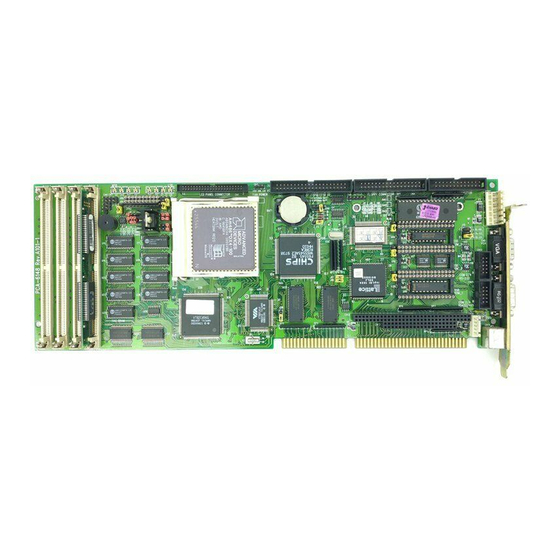
Page 13: Board Layout
Board layout CON1* CN15 CN16 CN10 CN11 CN13 CN12 CN1* JRN3 JRN2 JRN1 DLE1 SIM0 SIM1 SIM2 SIM3 *PCA-6148 only PCA-6148/6148L PCB Layout Chapter 1 Hardware Configuration... -
Page 14: Jumpers And Connectors
CMOS erase CPU voltage select SSD memory select COM2 RS-232/422/485 select SSD memory select SSD I/O address select SSD I/O address select SSD memory select IRQ 12 setting DLE1 JRN1 CPU Select JRN2 CPU Select JRN3 CPU Select PCA-6148/6148L User's Manual... - Page 15 PCA-6148/6148L Connectors Number Function *CN1 Flat panel display connector fan power connector IDE connector floppy connector parallel port connector power LED and keylock connector external speaker infraredTx/Rx header *CN9 VGA display connector CN10 COM2 RS-232 connector CN11 COM2 422/485 connector...
-
Page 16: Safety Precautions
CPU card. Modern electronic devices are very sensitive to static electric charges. Use a grounding wrist strap at all times. Place all electronic components on a static-dissipative surface or in a static-shielded bag when they are not in the chassis. PCA-6148/6148L User's Manual... -
Page 17: Jumper Settings
Jumper settings This section tells how to set the jumpers to configure your card. It gives the card default configuration and your options for each jumper. After you set the jumpers and install the card, you will also need to run the BIOS Setup program (discussed in Chapter 3) to configure the serial port addresses, floppy/hard disk drive types and system operating parameters. -
Page 18: Cpu Jumper Settings
CPU Jumper Settings Voltage 3.3V 3.45V 3.6V Frequency PCA-6148/6148L User's Manual... -
Page 19: Cpu Type Select
CPU type select In order for the system to function properly, the jumpers must be set to accommodate the CPU installed on the CPU card. CPU type select CPU Type Voltage Frequency JRN1 JRN2 JRN3 Cyrix 3.45V* 33M* 5x86-100 Cyrix 3.45V* 40M* 5x86-120... - Page 20 CPU type select CPU Type Voltage Frequency JRN1 JRN2 JRN3 3.3V* 33M* DX4-100 (NV8T) 3.3V* 33M* DX4-100 (SV8B) 3.3V* 40M* DX4-120 (SV8B) 3.3V* 33M* 5x86-133 *Please refer to jumper settings on page 10 of chapter 1 PCA-6148/6148L User's Manual...
- Page 21 CPU type select CPU Type Voltage Frequency JRN1 JRN2 JRN3 33M* DX2-66 3.3V* 33M* DX4-100 Intel 33M* DX-33 Intel DX2-50 25M* *Please refer to jumper settings on page 10 of chapter 1 Chapter 1 Hardware Configuration...
- Page 22 CPU type select CPU Type Voltage Frequency JRN1 JRN2 JRN3 Intel 33M* DX2-66 Intel 3.3V* 33M* DX4-100 Cyrix 33M* DX2-66 Cyrix 3.6V* 40M* DX2-80 *Please refer to jumper settings on page 10 of chapter 1 PCA-6148/6148L User's Manual...
- Page 23 CPU type select CPU Type Voltage Frequency JRN1 JRN2 JRN3 Cyrix 3.45V* 33M* DX4-100 *Please refer to jumper settings on page 10 Chapter 1 Hardware Configuration...
-
Page 24: Watchdog Timer (J5)
Watchdog timer system reset/IRQ15 select (J5) Reset (default) IRQ15 COM2 settings for RS-232/422/485 (J15) COM2 settings for RS-232/422/485 RS-232 (CN10) RS-422 (CN11) RS-485 (CN11) (default) CMOS backup select Battery Backup Clean CMOS (default) JP12 IRQ12 setting PS2 Mouse IRQ12 (default) JP20 PCA-6148/6148L User's Manual... -
Page 25: Ssd Device Select [ J14 (U12), J16 (U16), J19 (U28)]
SSD Device Select [ J14 (U12), J16 (U16), J19 (U28)] J14 (U12) J16 (U16) J19 (U28) Flash open open open open open open SRAM closed closed closed BATTERY Select (J7) Battery Installation Setup (J7) None (default) Internal 4 pin external 2 pin external 1 SSD power 2 Internal battery... - Page 26 PCA-6148/6148L User's Manual...
-
Page 27: Chapter 2: Connecting Peripherals
Connecting peripherals This chapter tells how to connect periph- erals, switches and indicators to the PCA- 6148/6148L board. You can access most of the connectors from the top of the board while it is installed in the chassis. If you have a number of cards installed, or your chassis is very tight, you may need to partially remove the card to make all the connections. -
Page 28: Pca-6148 Jumpers And Connectors List
PCA-6148/6148L Jumper and Connector List PCA-6148/6148L Connectors Number Function *CN1 Flat panel display connector fan power connector IDE connector floppy connector parallel port connector power LED and keylock connector external speaker infraredTx/Rx header *CN9 VGA display connector CN10 COM2 RS-232 connector... -
Page 29: Ide Connectors (Cn3)
(+5V) and panel video signals are stable. Under normal operation the control signal (ENAVEE) is active high. When the PCA-6148/6148L's power is applied, the control signal is low until just after the relevant flat panel signal is present. Configuration of the VGA interface is done completely via the software utility. -
Page 30: Floppy Drive Connector (Cn4)
Floppy drive connector (CN4) You can attach up to two floppy disk drives to the PCA-6148/ 6148L's on-board controller. You can use any combination of 5.25" (360 KB and 1.2 MB) and/or 3.5" (720 KB, 1.44 MB and 2.88 MB) drives. -
Page 31: Keyboard & Ps/2 Mouse Connectors (Cn14, Cn16)
Keyboard & PS/2 mouse connectors (CN14, CN16) CN16, the card's keyboard connector, is a 6-pin mini-DIN connec- tor on the card mounting bracket. The PCA-6148/6148L also comes with an adapter to convert to a standard DIN connector and to a PS/2 mouse connector. -
Page 32: Reset Switch (J1)
HDD is active. Marks on the Board layout (chapter 1, p. 5) indicate LED polarity. VGA display connector (CN9) The PCA-6148 provides a VGA controller for high resolution VGA interface. CN9 is a DB-15 connector for VGA monitor input. Serial Ports The PCA-6148/6148L offers two serial ports: COM1 in RS-232, COM2 in RS-232/422/485. -
Page 33: Connection (Cn15)
Serial port connections (CN15, CN10, CN11) Connector Address CN15 (COM1)RS-232 CN10 (COM2)RS-232 CN11 (COM2)RS-422/485 RS-232 connection (CN15) Different devices implement the RS-232 standard in different ways. If you are having problems with a serial device, be sure to check the pin assignments for the connector. The following table shows the pin assignments for the card's RS-232 port: RS-232 connector pin assignments Signal... - Page 34 RS-232/422/485 connector pin assignments (CN10, CN11) RS-232 (CN10) RS-422/485 (CN11) TX - or send data - (DTE) TX + or send data + (DTE) RX + or receive data + (DTE) RX - or receive data - (DTE) CN10 CN11 PCA-6148/6148L User's Manual...
-
Page 35: Power Connectors (Con1)
Power connectors (CON1) If you prefer not to acquire power through PCA-6148/6148L's backplane via the gold H-connectors, J1 also provides power input connectors for +5 V and ±12 V. Warning! Before making the connection, make sure the voltage is absolutely correct and matched with the right connector. -
Page 36: Infrared Tx/Rx Header (Cn8)
External Speaker (CN7) The CPU has its own buzzer. You can also connect to the external speaker on your computer chassis. Pin assignments for CN7 are the following: External speaker (CN7) Function Speaker out No connection +5 VDC PCA-6148/6148L User's Manual... -
Page 37: Power Led And Keylock (Cn6)
Power LED and Keylock (CN6) You can use a LED to indicate when the CPU card is on. Pin 1 of CN6 supplies the LED's power, and Pin 3 is the ground. You can use a switch (or a lock) to disable the keyboard so the PC will not respond to any input. - Page 38 PCA-6148/6148L User's Manual...
-
Page 39: Chapter 3: Award Bios Setup
AWARD BIOS SETUP This chapter describes how to set the card’s BIOS configuration data. Chapter 3 Award BIOS setup... -
Page 40: Entering Setup
This type of information is stored in battery-backed RAM so that it retains the Setup information when the power is turned off. Entering setup Turning on the computer and pressing <DEL> immediately will allow you to enter Setup. PCA-6148/6148L User's Manual... -
Page 41: Standard Cmos Setup
Standard CMOS setup Choose the "STANDARD CMOS SETUP" option from the INITIAL SETUP SCREEN Menu, and the screen below is displayed. This standard Setup Menu allows users to configure system components such as date, time, hard disk drive, floppy drive, display, and memory. R O M I S A B I O S (2C4L6AK1) S T A N D A R D C M O S S E T U P A W A R D S O F T W A R E , I N C . -
Page 42: Bios Features Setup
Type "Y" to accept write or "N" to abort write Award Software, Inc. You can run the anti-virus program to locate the problem. If Virus Warning is Disabled, no warning message will appear if anything attempts to access the boot sector or hard disk partition. PCA-6148/6148L User's Manual... - Page 43 CPU Internal Cache/External Cache Depending on the CPU/chipset design, these options can speed up memory access when enabled. Quick Power On Self Test This option speeds up the Power-On Self Test (POST) conducted as soon as the computer is turned on. When enabled, BIOS shortens or skips some of the items during the test.
- Page 44 Typematic Rate: 6, 8, 10, 12, 15, 20, 24, 30. Typematic Delay (msec) When holding down a key, the Typematic Delay is the time interval between the appearance of the first and second characters. The input values (msec) for this category are: 250, 500, 750, 1000. PCA-6148/6148L User's Manual...
- Page 45 Security Option This setting determines whether the system will boot if the pass- word is denied, while limiting access to Setup. Note: To disable security, select PASSWORD SETTING in the main menu. At this point, you will be asked to enter a password. Simply hit the <ENTER>...
-
Page 46: Chipset Features Setup
By choosing the "CHIPSET FEATURES SETUP" option from the CMOS SETUP screen menu, the following screen is displayed. This sample screen contains the manufacturer's default values for the PCA-6148/6148L board. ROM ISA BIOS (2C4L6AK1) CMOS SETUP UTILITY CHIPSET FEATURES SETUP... -
Page 47: Video Bios Cacheable
Video BIOS Cacheable As with caching the System BIOS above, enabling the Video BIOS cache will cause access to video BIOS addressed at C0000H to C7FFFH to be cached, if the cache controller is also enabled. Enabled Video BIOS access cached Disabled Video BIOS access not cached Disabled is the default. -
Page 48: Power Management Setup
This category determines the system's power consumption after selecting the following items. Default value is disable. The following pages tell you the options of each item and describe the meanings of each option. PCA-6148/6148L User's Manual... -
Page 49: Doze Mode
Power Management Item Options Descriptions Power Management 1. Disable Global power management will be disabled 2. User Define Users can configure their own power management 3. Min Saving Pre-defined timer values are used such that all timers are at their MAX value 4. -
Page 50: Standby Mode
System will never enter SUSPEND mode Defines the continuous idle time 8 sec before the system enters 32 sec SUSPEND mode.*** 2 min 8 min 16 min Note: Normally, STANDBY mode puts the system into low speed or 8 MHz. PCA-6148/6148L User's Manual... -
Page 51: Important Notice
Important Notice The status of the following items will affect Doze Mode, Standby Mode and Suspend Mode: PCI Master Activity, COM Ports Activity, LPT Ports Activity, HDD Ports Activity, DMA Ports Activity, VGA Activity, IRQ3 (COM2), IRQ4 (COM1), IRQ5 (LPT2), IRQ6 (Floppy Disk), IRQ7 (LPT1), IRQ8 (RTC Alarm), IRQ9 (IRQ2 Redir), IRQ10 (Reserved), IRQ11 (Reserved), IRQ12 (PS/2 Mouse), IRQ13 (Coprocessor), IRQ14 (Hard Disk), and IRQ15 (Reserved) -
Page 52: Load Bios Defaults
This record is required for the system to operate. Exit without saving Selecting this option and pressing the [Enter] key lets you exit the Setup program without recording any new values or changing old ones. PCA-6148/6148L User's Manual... -
Page 53: Chapter 4: Vga Display Software/Hardware Configuration
VGA Display Software/ Hardware Configuration This chapter details the software configu- ration information. It shows you how to configure the board to match your application requirements. AWARD System BIOS is covered in Chapter 4. Sections include: • LCD display configuration •... -
Page 54: Introduction
You can change the display BIOS simply by reprogramming the Flash chip. PCA-6148 Utility Disk The PCA-6148 is supplied with a software utility disk that holds the necessary file for setting up the VGA display controller. The disk’s directory and file structure is as follows: ROOT MAKEROM.EXE... -
Page 55: Vga Display Software Configuration
Configure the VGA display as follows: 1. Apply power to the PCA-6148 with a color TFT display attached. This is the default setting for the PCA-6148. Ensure that the AWDFLASH.EXE and *.BIN files are located in the working drive. - Page 56 BIOS. Press N to exit the program. The new VGA configuration will then write to the ROM BIOS chip. This configuration will remain the same until you run the AWDFLASH.EXE program and change the settings. PCA-6148/6148L User's Manual...
-
Page 57: Chapter 5: Svga Setup
SVGA Setup (PCA-6148 only) The PCA-6148 features an on-board flat panel/VGA interface. This chapter provides instructions for installing and operating the software drivers on the included display driver diskette. Chapter 5 SVGA Setup... -
Page 58: Simultaneous Display Mode
Both CRT and panel displays can be used simultaneously. The PCA-6148 can be set in one of three configurations: on a CRT, on a flat panel display, or on both simultaneously. The system is initially set to simultaneous display mode. -
Page 59: Software Support
Software support The drivers support the following applications using the filenames and resolutions listed: Application Filename Resolution Colors Windows 3.1 LINEAR4.DRV 640x480 800x600 1024x768 LINEAR8.DRV 640x480 800x600 1024x768 LINEAR16.DRV 640x480 LINEAR24.DRV 640x480 AutoCAD R12 RCTURBOC.EXP 640x480 800x600 1024x768 640x480 800x600 1024x768 640x480 640x480... -
Page 60: Driver Installation
The display driver diskette contains drivers for several versions of certain applications. You must install the correct version in order for the driver to work properly so make sure you know which version of the application you have. PCA-6148/6148L User's Manual... -
Page 61: Windows Setup
Windows setup These drivers are designed to work with Microsoft Windows 3.1. You may install these drivers through Windows or in DOS. Step 1: Install Windows as you normally would for a VGA display. Run Windows to make sure that it is working correctly. Step 2: Place the display driver diskette in drive A. - Page 62 Setup, repeating steps 4 and 5 from the previ- ous page. Besides the special display drivers marked by an asterisk (*), you should be able to use the following standard drivers: 640x480, 16 colors Super VGA 800x600, 16 colors PCA-6148/6148L User's Manual...
- Page 63 Panning Drivers Special panning drivers are provided to allow high-resolution modes to be displayed on a flat panel or CRT. These drivers will show a section of a larger screen and will automatically pan, or scroll, the screen horizontally and vertically when the mouse reaches the edge of the display.
-
Page 64: Autocad R12
Select Configure Video Display. In Display Device Configura- tion choose Select Graphics Board/Resolution. Then choose Select Display Graphics Board. After choosing a graphics board, go to Select Display Resolution. After selecting the display resolution, save the new configuration, and return to the main menu. PCA-6148/6148L User's Manual... - Page 65 Basic Configuration Menu This menu allows you to modify: Number of AutoCAD Command Lines Font Size 6x8/8x8/8x14/8x16/12x20/12x24 Dual Screen Enable/Disable User Interface Configuration Double Click Interval Time BP Button BP Highlight Patt Line/Xor Rect/Both BP Refresh Enable/Disable BP Cache Enable/Disable Expert Configuration Menu This menu allows you to modify: Display List...
-
Page 66: Lotus 1-2-3 And Lotus Symphony
Step 4: After the selection of the appropriate VGA display driver, you will need to exit this menu and return to the Main Lotus Installation Menu. Do this by selecting Return To Menu. Step 5: At the Main Lotus Installation Menu, select Save Changes. PCA-6148/6148L User's Manual... - Page 67 Step 6: At this point the Installation Menu will prompt you for the name of your new Lotus configuration file. The Lotus system will prompt you with the default value — 123.SET, but you may want to use a filename that indicates the resolution of its driver. For example, if you installed the 132 column by 25 line driver, you could name this driver 132X25.SET, or if you installed the 80 by 50 driver, you may want to call the file 80X50.SET.
-
Page 68: Vesa
Make sure that your monitor is capable of displaying these high resolution modes before enabling them. NOTE: If the video BIOS already supports VBE extended video modes, DO NOT use this driver. Run the VTEST.EXE program to see if the video BIOS supports the VBE modes. PCA-6148/6148L User's Manual... -
Page 69: Word
Word These drivers are designed to work with Microsoft Word 5.0 and 5.5. Driver installation If you have already installed Word on your computer, go to Step 2 to install the new video driver. Step 1: Install Word as normal. Step 2: After you complete the Word installation, place the display driver diskette into drive A. -
Page 70: Wordperfect
Press <ESC> followed by Y to exit to DOS. Step 2: Start WordPerfect, and press <SHIFT>+<F1> to enter the setup menu. Select D for Display and G for Graphics Screen Type, and then choose the desired Chips VGA resolution. PCA-6148/6148L User's Manual... - Page 71 Configuring WordPerfect 5.0 for 132 columns Follow these instructions to configure WordPerfect 5.0 for 132 column text mode: Step 1: To use the SETCOL program to set 132 columns and 25 rows, type the following command: SETCOL 132, 25 <ENTER> Step 2: Start WordPerfect.
- Page 72 PCA-6148/6148L User's Manual...
-
Page 73: Appendix A: Flash/Ram/Rom Solid State Disk
Flash/RAM/ROM Solid State Disk Appendix A Flash/RAM/ROM disk... -
Page 74: Memory Devices
The PCA-6148/6148L features an internal Flash/RAM/ROM disk drive. This drive emulates a floppy disk drive by using solid-state memory chips (Flash, RAM or ROM) to store programs and data instead of the magnetic particles on the mechanical drive’s disk. The Flash/RAM/ROM disk offers much faster access times than a floppy or hard disk and greatly increases reliability in harsh environments. -
Page 75: Drive Capacity
disk; you need not use an external programmer. If you use +12 V Flash memories (28F010) you will still need an "external program- mer" to write data. Drive capacity The size of the emulated drive depends on the size and number of the chips you install. - Page 76 Control the DOS drive emulated by the Flash/RAM/ROM disk: 1st, 2nd, 3rd or 4th. SSD Driver Emulated The actual drive letter assigned by DOS to the Flash/RAM/ROM disk depends on the floppy or hard disks installed in the system. PCA-6148/6148L User's Manual...
-
Page 77: Drive Selection
Drive Selection Floppy disks The Flash/RAM/ROM disk will "replace" the corresponding floppy disk. For example, if you have a single floppy disk (drive A:) and assign the Flash/RAM/ROM disk to be the 1st drive, any drive operations directed at drive A: will go to the Flash/RAM/ ROM disk. -
Page 78: Solid State Disk (Ssd) Formatting
If the disk size dow not match your assignment, please check the SSD setup again. If you need a bootable disk, you should do the system transfter by typing: SYS drv: or use Format command and /S parameters. PCA-6148/6148L User's Manual... -
Page 79: Booting From The Flash/Ram/Rom Disk
Inserting memory devices After you’ve set all the jumpers and switches on the PCA-6148, insert the appropriate memory devices into the card’s sockets. Remember that you will need to program EPROMs before you insert them. -
Page 80: Ssd Jumper Setting
J19 and set J7. The will support SRAM power from the battery that is used to retain the SRAM data when the PC's power is turned off. Set jumper J7 according to the battery type that will be used. PCA-6148/6148L User's Manual... -
Page 81: File Copy Utility
Battery Installation Setup (J7) None (default) Internal 4 pin external 2 pin external Pin 1 SSD power Pin 2 Internal battery Pin 3 SSD Power Pin 4 GND The battery should be disconnected when using non-volatile memory devices such as Flash memories or EPROMs. You can use 3 V or 3.6 V Lithium battery 2 pin or 4 pin connectors for SRAM data retention power. -
Page 82: Using A Memory Manager (Emm386.Exe)
This excludes an 8 KB range for the card from D0000 to D1FFF (the default addresses). You should also make sure that the disk's memory address is not shadowed in the BIOS. SSD program will occupy C8000 - CBFFF when BIOS SSD setting is enabled. PCA-6148/6148L User's Manual... -
Page 83: Appendix B: Programming The Watchdog Timer
Programming the Watchdog Timer The PCA-6148 is equipped with a watchdog timer that resets the CPU or generates an interrupt if processing comes to a standstill for whatever reason. This feature ensures system reliability in industrial stand-alone and unmanned environments. - Page 84 Step 4 Your application program task #2 Step 5 Out 443h data REM Reset the timer Step 6 in 043h, REM Disable the watchdog timer Data Values 1 sec. 2 sec. 3 sec. 4 sec. 63 sec. PCA-6148/6148L User's Manual...
-
Page 85: Appendix C: Upgrading
Upgrading This appendix gives instructions for increasing the capabilities of your CPU card. It covers: • Installing PC/104 • DRAM memory installation (SIMMs) -
Page 86: Installing Pc/104 Modules (Cn12,Cn13)
Installing PC/104 modules (CN12,CN13) The PCA-6148 card's PC/104 connector lets you attach PC/104 modules. These modules perform the functions of traditional plug- in expansion cards, but save space and valuable slots. Advantech modules include: • PCM-3110 PCMCIA module • PCM-3718 30 KHz A/D module •... - Page 87 PC/104 module dimensions (mm) Appendix C Upgrading...
-
Page 88: Installing Dram (Simms)
Installing DRAM (SIMMs) You can use anywhere from 1 MB to 128 MB of DRAM with your PCA-6148. The card provides four 72-pin SIMM (single in-line memory module) socket that accepts from 1 to 32 MB SIMMs. The following table shows the bank assignment for the SIMM... -
Page 89: Supported 36 Bit Memory Configurations (Single Bank)
BANK0 BANK1 BANK2 BANK3 BANK4 TOTAL 10MB 18MB 12MB 18MB 20MB 24MB 36MB 12MB 16MB 20MB 24MB 36MB 40MB 16MB 16MB 32MB 48MB 64MB 32MB 64MB 64MB 128MB Supported 36 bit Memory Configurations (single bank) Appendix C Upgrading... - Page 90 PCA-6148/6148L User's Manual...
-
Page 91: Appendix D: Detailed System Information
Detailed system information This appendix contains information of a detailed or specialized nature. It in- cludes: • Parallel connector pin assignments • HDD connector pin assignments • FDD connector pin assignments • Keyboard connector pin assignments • CRT display connector •... -
Page 92: Parallel/Printer Connector (Cn5)
DATA 6 DATA 7 - ACKNOWLEDGE BUSY PAPER EMPTY + SELECT - AUTO FEED - ERROR - INIT PRINTER - SELECT INPUT 18-25 GROUND HDD connector (CN3) Pin no. Signal Pin no. Signal - RST N.C. N.C. PCA-6148/6148L User's Manual... - Page 93 Pin no. Signal Pin no. Signal IORDY BALE N.C. -IO CS16 N.C. A2 CS0 -ACT FDD connector (CN4) Pin no. Signal 1-33 (odd) GROUND HIGH DENSITY 4, 6 UNUSED INDEX MOTOR ENABLE A DRIVER SELECT B DRIVER SELECT A MOTOR ENABLE B DIRECTION STEP PULSE WRITE DATA...
-
Page 94: Vga Display Connector (Cn9)
*VGA display connector (CN9) PCA-6148 VGA display connector Signal Signal GREEN BLUE H-SYNC V-SYNC *Flat panel display connector (CN1) PCA-6148 Flat panel display connector Function Function +12 V +12 V ENAVEE SHFCLK ENABKL KB-DATA KB-CLK PCA-6148/6148L User's Manual... -
Page 95: Rs-232 Connections
RS-232 connections Different devices implement the RS-232 standard in different ways. If you are having problems with a serial device, be sure to check the pin assignments for the connector. The following table shows the pin assignments for the card's RS-232 port: RS-232 connector pin assignment (CN15, CN10) Signal CN15... - Page 96 RS-422/485 connector pin assignments (C11) RS-422/485 (CN11) TX - or send data - (DTE) TX + or send data + (DTE) RX + or receive data + (DTE) RX - or receive data - (DTE) CN11 PCA-6148/6148L User's Manual...
- Page 97 PC/104 Connector Pin Assignments CN12 CN13 IOCHCHK* 0V SBHE* MEMCS16* RESETDRV LA23 IOCS16* LA22 IRQ10 IRQ9 LA21 IRQ11 LA20 IRQ12 DRQ2 LA19 IRQ15 -12V LA18 IRQ14 ENDXFR* LA17* DACK0* MEMR* DRQ0* IOCHRDY (KEY) MEMW* DACK5* SMEMW* DRQ5 SA19 SMEMR* DACK6* SA18 IOW* SD10...
- Page 98 F0000h - FFFFFh System BIOS C8000h - EFFFFh Unused C0000h - C7FFFh VGA BIOS A0000h - BFFFFh VGA display memory 00000h - 9FFFFh Base Memory DMA channel assignments Channel Function Available Available Floppy Available [Cascade] Available Available Available PCA-6148/6148L User's Manual...
- Page 99 IRQ/DMA detection interrupt assignments Interrupt # Interrupt source IRQ 00 Timer IRQ 01 Keyboard IRQ 02 [CASCADE] IRQ 03 COM2 (2F8h) IRQ 04 COM1 (3F8h) IRQ 05 Available IRQ 06 Floppy IRQ 07 LPT1 (378h) IRQ 08 Clock/Cal IRQ 09 Available IRQ 10 Available...
- Page 100 PCA-6148/6148L User's Manual...
-
Page 101: Appendix E: Post Leds
POST LEDs This appendix lists the codes generated by the POST (Power On Self Test) routines. It also discusses how to read the PCA- 6148's POST LED indicators. - Page 102 You can also determine the number of the test that failed by reading the LED indicators on the top of the PCA-6148 board. Please make a note of any POST codes before you contact Advantech for technical support.
- Page 103 I/O address 80H. If the test fails, the code will stay in memory. You can read the code and determine which test has failed. The PCA-6148’s POST LED indicators make this process ex- tremely easy. You don’t need any special diagnostic tools, you just read the POST code from the LEDs.
- Page 104 Code Name Description of check-point PCA-6148/6148L User's Manual...
- Page 105 Code Name Description of check-point Appendix E POST LEDs...
- Page 106 Code Name Description of check-point PCA-6148/6148L User's Manual...
- Page 107 Code Name Description of check-point Appendix E POST LEDs...
- Page 108 PCA-6148/6148L User's Manual...
Need help?
Do you have a question about the PCA-6148 and is the answer not in the manual?
Questions and answers