
Subscribe to Our Youtube Channel
Related Manuals for Advantech PCA-6179


Summary of Contents for Advantech PCA-6179
- Page 1 PCA-6179 ® Full-size socket 370 Intel ® Pentium III processor- based PCI/ISA-bus CPU card...
-
Page 2: Copyright Notice
Copyright notice This document is copyrighted, 2000, by Advantech Co., Ltd. All rights are reserved. Advantech Co., Ltd. reserves the right to make improvements to the products described in this manual at any time without notice. No part of this manual may be reproduced, copied, translated or transmitted in any form or by any means without the prior written permission of Advantech Co., Ltd. -
Page 3: Technical Support
A Message to the Customer Advantech customer services Each and every Advantech product is built to the most exacting specifications to ensure reliable performance in the harsh and demanding conditions typical of industrial environments. Whether your new Advantech equipment is destined for the laboratory or the... - Page 4 l e t I I I ® ® o l l & © e t l...
-
Page 5: Product Warranty
Advantech assumes no liability under the terms of this warranty as a consequence of such events. If an Advantech product is defective, it will be repaired or replaced at no charge during the warranty period. For out-of-warranty repairs, you will be billed according to the cost of replacement materials, service time and freight. -
Page 6: Initial Inspection
It should be free of marks and scratches and in perfect working order upon receipt. As you unpack the PCA-6179, check it for signs of shipping damage. (For example, damaged box, scratches, dents, etc.) If it is damaged or it fails to meet the specifications, notify our service department or your local sales representative immediately. -
Page 7: Table Of Contents
Contents Chapter 1 Hardware Configuration ......1 Introduction ................2 Features ................3 Specifications ..............5 1.3.1 System .................5 1.3.2 Memory ...............5 1.3.3 Input/Output ..............6 1.3.4 VGA interface .............6 1.3.5 SCSI interface .............6 1.3.6 Ethernet LAN ..............6 1.3.7 Solid state disk ............6 1.3.8 Industrial features ............7 1.3.9 Mechanical and environmental specifications ....7 Board Layout: Main Features ..........8 Jumpers and Connectors ...........9... - Page 8 Primary (CN1) and Secondary (CN2) IDE Connectors24 Floppy Drive Connector (CN3) ........25 Parallel Port (CN4) ............25 SCSI Connector (CN5) ............26 USB Port (CN6) ..............27 VGA Connector (CN7) ............27 10/100Base-T Ethernet Connector (CN8) ......28 Serial Ports (CN9: COM1; CN10: COM2) ....28 PS/2 Keyboard and Mouse Connector (CN11) .....29 2.10 External Keyboard Connector (CN12) ......29 2.11 Infrared (IR) Connector (CN13) ........30...
- Page 9 3.4.6 Typematic Rate Setting ..........40 3.4.7 Typematic Rate (Chars/Sec) ........41 3.4.8 Typematic Delay (msec) ........... 41 3.4.9 Security Option ............41 3.4.10 OS Select for DRAM > 64MB........ 41 3.4.11 Video BIOS Shadow ..........41 3.4.12 C8000-CBFFF Shadow / DC000-DFFFF Shadow .42 Advanced Chipset Features..........42 3.5.1 Memory Hole At 15 M ~ 16 M .........43 3.5.2 AGP Aperture Size (MB) ..........
- Page 10 Before You Begin .............52 Features ................52 Installation ................53 Chapter 5 LAN Configuration ........55 Introduction ..............56 Features ................56 Driver Installation ............57 Windows 9X Drivers Setup Procedure ..................58 Windows NT Drivers Setup Procedure ......65 Windows 2000 Drivers Setup Procedure .......70 Chapter 6 SCSI Setup and Configurations....77 Introduction ..............78 Before You Begin .............78 Basic Rules for SCSI Host Adapter and Device Installa-...
- Page 11 B.10 External Keyboard Connector (CN12) ......110 B.11 IR Connector (CN13) .............111 B.12 CPU Fan Power Connector (CN14) ......111 B.13 Power LED and Keylock Connector (CN16) ....112 B.14 External Speaker Connector (CN17) ......112 B.15 Reset Connector (CN18) ..........113 B.16 HDD LED Connector (CN19) ........113 B.17 ATX Feature Connector (CN20) ........113 B.18 System I/O Ports ............114 B.19 DMA Channel Assignments ..........
- Page 12 Tables Table 1-1: Jumpers ......................9 Table 1-2: Connectors ....................10 Table 1-3: CPU clock ratio setting (SW1) ..............14 Table 1-6: Watchdog timer output (J2) ................15 Table 1-7: DiskOnChip® 2000 Flash disk memory address jumper settings (J3) ..17 Table 1-8: DIMM module allocation table ..............
- Page 13 Figures Figure 1-1: Board layout: main features ............... 8 Figure 1-2: Board layout: jumper and connecter locations ..........11...
-
Page 16: Chapter 1 Hardware Configuration
Hardware Configuration This chapter gives background informa- tion on the PCA-6179. It then shows you how to configure the card to match your application and prepare it for installation into your PC. Sections include: • Introduction • Features • Specifications •... -
Page 17: Introduction
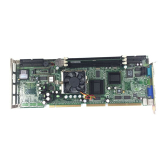
Introduction The PCA-6179 Series all-in-one industrial grade CPU card uses Intel's ® highly acclaimed Pentium III processor, together with the VIA Apollo Pro133A chipset. The card works with standard ISA or PCI/ISA-bus passive backplanes. The CPU provides 256 KB on-CPU L2 cache, eliminating the need for external SRAM chips. -
Page 18: Features
Features 1. Fan status monitoring and alarm: To prevent system overheating and damage, the CPU fan can be monitored for speed and failure. The fan is set for its normal RPM range and alarm thresholds. 2. Temperature monitoring and alert: To prevent system overheating and damage, the CPU card supports processor thermal sensing and auto-protection. - Page 19 In this case, a warning message will be displayed. You can then run your anti-virus program to locate the problem PCA-6179 User's Manual...
-
Page 20: Specifications
Specifications 1.3.1 System ® • CPU: Intel Pentium III processor, up to 933+ MHz, FSB 100/133 • BIOS: Award Flash BIOS, 2 Mbit • System Chipset: VIA Apollo Pro133A • Green function: Supports power management operation via BIOS. Activated by keyboard or mouse activity •... -
Page 21: Input/Output
80 MB/sec. • Chipset: Symbios SYM53C895 1.3.6 Ethernet LAN • Supports 10/100Base-T Ethernet networking • Chipset: Realtek 8139C 1.3.7 Solid state disk ® • Supports DOC 2000 up to 144 MB PCA-6179 User's Manual... -
Page 22: Industrial Features
1.3.8 Industrial features • Watchdog timer: Can generate a system reset or IRQ11. The watchdog timer is programmable, with each unit equal to one second (63 levels). The program uses I/O port hex 443h to control the watchdog timer 1.3.9 Mechanical and environmental specifications •... -
Page 23: Board Layout: Main Features
Board Layout: Main Features Figure 1-1: Board layout: main features PCA-6179 User's Manual... -
Page 24: Jumpers And Connectors
Jumpers and Connectors Connectors on the PCA-6179 board link it to external devices such as hard disk drives and a keyboard. In addition, the board has a number of jumpers used to configure your system for your application. The tables below list the function of each of the board jumpers and connectors. -
Page 25: Table 1-2: Connectors
CN13 Infrared (IR) connector CN14 CPU fan connector CN16 Keyboard lock and power LED CN17 External speaker CN18 Reset connector CN19 HDD LED connector CN20 ATX feature connector CN21 ATX soft power switch CN22 Reserved (Default closed) PCA-6179 User's Manual... -
Page 26: Board Layout: Jumper And Connector Locations
Board Layout: Jumper and Connector Locations Figure 1-2: Board layout: jumper and connecter locations Chapter 1 Hardware Configuration... -
Page 27: Safety Precautions
As a safety precaution, use a grounding wrist strap at all times. Place all electronic components in a static-dissipative surface or static-shielded bag when they are not in the chassis. PCA-6179 User's Manual... -
Page 28: Jumper Settings
1 and 2, or 2 and 3. A pair of needle-nose pliers may be useful when setting jumpers. 1.8.2 CPU clock ratio setting (SW1) You must configure your PCA-6179 CPU card to the frequency of ® your Intel Coppermine processor by setting jumper SW1. -
Page 29: Cmos Clear (J1)
1.8.4 CMOS clear (J1) The PCA-6179 CPU card contains a jumper that can erase CMOS data and reset the system BIOS information. Normally this jumper should be set with pins 1-2 closed. If you want to reset the CMOS data, set J1 to 2-3 closed for just a few seconds, and then move the jumper back to 1-2 closed. -
Page 30: Diskonchip 2000 Flash Disk Address Select (Sw3)
1.8.5 DiskOnChip 2000 Flash disk address select (SW3) ® The PCA-6179 includes a 32-pin socket for M-Systems' DiskOnChip 2000 Flash disk module. This revolutionary solid state disk enables critical system information to be stored within an on-board Flash disk for virtually instantaneous data access. - Page 31 ® Table 1-7: DiskOnChip 2000 Flash disk memory address jumper settings (J3) Segment SW3-1 SW3-2 SW3-3 SW3-4 CC00h D000h D400h D800h DC00h E000h Disable Chapter 1 Hardware Configuration...
-
Page 32: System Memory
(16, 32, 64, 128, 256 or 512 MB) x 1 1.9.1 Sample calculation: DIMM memory capacity Suppose you install a 128 MB DIMM into your PCA-6179's socket 1 and a 32 MB DIMM into sockets 2 and 3. Your total system memory... -
Page 33: Supplementary Information About Dimms
1.9.2 Supplementary information about DIMMs Your PCA-6179 can accept SDRAM memory chips (with or without parity). Also note: • If the PCA-6179 operates at 133 MHz, only use PC/133-compliant DIMMs. Most systems will not even boot if non-compliant modules are used. This is due to strict timing issues involved at this speed. -
Page 34: Memory Installation Procedures
Coppermine processor, you do not have to take care of either SRAM chips or SRAM modules. The built-in second level cache in the Coppermine processor yields much higher performance than the ® external cache memories. The cache size in the Intel Coppermine processor is 256 KB. PCA-6179 User's Manual... -
Page 35: Cpu Installation
1.12 CPU Installation ® The PCA-6179 provides a socket 370 for an Intel Coppermine processor. The CPU on the board must have a fan or heat sink attached, to prevent overheating. Warning: Without a fan or heat sink, the CPU will overheat and cause damage to both the CPU and the motherboard. - Page 36 PCA-6179 User's Manual...
-
Page 37: Chapter 2 Connecting Peripherals
Connecting Peripherals This chapter tells how to connect periph- erals, switches and indicators to the PCA-6179 board. You can access most of the connectors from the top of the board while it is installed in the chassis. If you have a number of cards installed, or your... -
Page 38: Primary (Cn1) And Secondary (Cn2) Ide Connectors24
Connectors You can attach up to four IDE (Integrated Device Electronics) drives to the PCA-6179’s internal controller. The primary (CN1) and secondary (CN2) connectors can each accommodate two drives. Wire number 1 on the cable is red or blue and the other wires are gray. -
Page 39: Floppy Drive Connector (Cn3)
Floppy Drive Connector (CN3) You can attach up to two floppy disk drives to the PCA-6179's onboard controller. You can use any combination of 5.25" (360 KB / 1.2 MB) and/or 3.5" (720 KB / 1.44/2.88 MB) drives. The card comes with a 34-pin daisy-chain drive connector cable. On one end of the cable is a 34-pin flat-cable connector. -
Page 40: Scsi Connector (Cn5)
CN4. SCSI Connector (CN5) The PCA-6179 has a 68-pin, dual in-line connector for Ultra2 Wide SCSI devices. Connection of SCSI devices requires special attention, especially when determining the last drive on the SCSI chain. Refer to Chapter 6 and your device's operating manual for detailed installation advice. -
Page 41: Usb Port (Cn6)
The USB interface can be disabled in the system BIOS setup. VGA Connector (CN7) The PCA-6179 includes a AGP SVGA interface that can drive conventional CRT displays. CN7 is a standard 15-pin D-SUB connec- tor commonly used for VGA. Pin assignments for CRT connector CN7 are detailed in Appendix B. -
Page 42: 10/100Base-T Ethernet Connector (Cn8)
Serial Ports (CN9: COM1; CN10: COM2) CN10 The PCA-6179 offers two serial ports, CN9 as COM1 and CN10 as COM2. These ports can connect to serial devices, such as a mouse or printers, or to a communication network. Table 2-1: Serial port connections (COM1, COM2) -
Page 43: Ps/2 Keyboard And Mouse Connector (Cn11)
PS/2 mouse connector. 2.10 External Keyboard Connector (CN12) CN12 In addition to the PS/2 mouse/keyboard connector on the PCA-6179's rear plate, there is also an extra onboard external keyboard connector. This gives system integrators greater flexibility in designing their systems. -
Page 44: Infrared (Ir) Connector (Cn13)
This module mounts on the system case. You must configure the setting through the BIOS setup (see Chapter 3). 2.12 CPU Fan Connector (CN14) CN14 PIN 1 This connector supports cooling fans of 500 mA (6 W) or less. PCA-6179 User's Manual... -
Page 45: Front Panel Connectors (Cn16, Cn17, Cn18, Cn19, Cn21 And Cn22)
2.13.2 External speaker (CN17) CN17 is a 4-pin connector for an extenal speaker. If there is no external speaker, the PCA-6179 provides an on-board buzzer as an alternative. To enable the buzzer, set pins 3-4 as closed. 2.13.3 Reset (CN18) Many computer cases offer the convenience of a reset button. -
Page 46: Hdd Led (Cn19)
CN21. 2.14.1 ATX feature connector (CN20) and soft power switch connector (CN21) The PCA-6179 can support an advanced soft power switch function if an ATX power supply is used. To enable the soft power switch function: 1. Take the specially designed ATX-to-PS/2 power cable out of the PCA-6179's accessory bag. -
Page 47: Controlling The Soft Power Switch
Warnings: 1. Make sure that you unplug your power supply when adding or removing expansion cards or other system components. Failure to do so may cause severe damage to both your CPU card and expan- sion cards. 2. ATX power supplies may power on if certain motherboard components or connections are touched by metallic objects. - Page 48 PCA-6179 User's Manual...
-
Page 49: Award Bios Setup
Award BIOS Setup This chapter describes how to set the card’s BIOS configuration data. -
Page 50: Introduction
CPU. If there is no number assigned to the patch code, please contact Advantech’s applications engineer to obtain an up-to-date patch code file. This will ensure that your CPU’s system status is valid. After ensuring that you have a number assigned to the patch code, press <Del>... -
Page 51: Standard Cmos Features
Standard CMOS Features Choose the “STANDARD CMOS FEATURES” option from the “INITIAL SETUP SCREEN” menu, and the screen below will be displayed. This standard setup menu allows users to configure system components such as date, time, hard disk drive, floppy drive, display, and memory. -
Page 52: Advanced Bios Features
If your boot device is LAN, when system boot, press <F10> when screen shows: Realtek RTL8139 (X) PXE/RPL BootROM Press F10 key to change bootstrap selection. Current Selection is -- Disable network boot Then, the following message will be displayed: PCA-6179 User’s Manual... -
Page 53: Virus Warning
Realtek Bootstrap selection menu 1.- Disable network boot 2.- Network boot using interrupt 18h 3.- Network boot using interrupt 19h 4.- Network boot using PnP/BEV (BBS) 5.- Network boot from RPL (Int18h/19h) Press 1, 2, 3, 4, or 5: --> The ability to enable the RTL8139(X) BootROM to boot from network depends on underly BIOS support. -
Page 54: Quick Power On Self Test
Keypad boots up to arrow keys. 3.4.5 Gate A20 Option Normal The A20 signal is controlled by the keyboard controller or chipset hardware. Fast (Default) The A20 signal is controlled by Port 92 or the chipset specific method. 3.4.6 Typematic Rate Setting PCA-6179 User’s Manual... -
Page 55: Typematic Rate (Chars/Sec)
The typematic rate determines the characters per second accepted by the computer. Typematic Rate Setting enables or disables the typemat- ic rate. 3.4.7 Typematic Rate (Chars/Sec) BIOS accepts the following input values (characters/second) for typematic rate: 6, 8, 10, 12, 15, 20, 24, 30. 3.4.8 Typematic Delay (msec) Typematic delay is the time interval between the appearance of two consecutive characters, when holding down a key. -
Page 56: C8000-Cbfff Shadow / Dc000-Dffff Shadow
By choosing the “ADVANCED CHIPSET FEATURES” option from the INITIAL SETUP SCREEN menu, the screen below will be displayed. This sample screen contains the manufacturer’s default values for the CPU Card. Figure 3-4: Advanced Chipset features screen PCA-6179 User’s Manual... -
Page 57: Memory Hole At 15 M ~ 16 M
3.5.1 Memory Hole At 15 M ~ 16 M Enabling this feature reserves 15 MB to 16 MB memory address space for ISA expansion cards that specifically require this setting. This makes memory from 15 MB and up unavailable to the system. Expansion cards can only access memory up to 16 MB. -
Page 58: Ide Primary Master/Slave Pio/Udma Mode, Ide Secondary Master/Slave Pio/Udma Mode (Auto)
3.6.7 Parallel Port Mode (ECP + EPP) This field allows you to set the operation mode of the parallel port. The setting “Normal” allows normal speed operation, but in one PCA-6179 User’s Manual... -
Page 59: Ecp Mode Use Dma
direction only. “EPP” allows bidirectional parallel port operation at maximum speed. “ECP” allows the parallel port to operate in bidirec- tional mode and at a speed faster than the maximum data transfer rate. “ECP + EPP” allows normal speed operation in a two-way mode. 3.6.8 ECP Mode Use DMA This selection is available only if you select “ECP”... -
Page 60: Power Management
You can choose “Delay 4 sec.” If you do, then pushing the button for more than 4 seconds will turn off the system, whereas pushing the button momentarily (for less than 4 seconds) will switch the system to “suspend” mode. PCA-6179 User’s Manual... -
Page 61: Wakeup Event
3.7.4 Wakeup Event 3.7.5 IRQs Activity Monitoring Figure 3-7: IRQs Activity Monitoring Chapter 3 Award BIOS Setup... -
Page 62: Pnp/Pci Configurations
PnP/PCI Configurations PC Health Status If you enable the OBS function, you can view the temperature, fan speed and voltage of your PC system. The data will be displayed in similar fashion to the display shown in following: PCA-6179 User’s Manual... -
Page 63: Frequency Control
3.10 Frequency Control 3.11 Load Setup Defaults “LOAD SETUP DEFAULTS” loads the values required by the system for maximum performance. 3.12 Set Password To change the password: 1. Choose the “SET PASSWORD” option from the Setup main menu and press <Enter>. The screen will display the following message: Enter Password: Press <Enter>. -
Page 64: Save & Exit Setup
This record is required for the system to operate. 3.14 Exit Without Saving Selecting this option and pressing <Enter> lets you exit the setup program without recording any new values or changing old ones. PCA-6179 User’s Manual... -
Page 65: Chapter 4 Agp Svga Setup
AGP SVGA Setup The PCA-6179 features an onboard PCI AGP/VGA interface. This chapter provides instructions for installing and operating the software drivers on the display driver CD included in your package. -
Page 66: Before You Begin
The enhanced display drivers for the PCA-6179 board are located on the software installa- tion CD. You must install the drivers and utility software by using the supplied SETUP program for DOS drivers. -
Page 67: Installation
• User-friendly installation for Windows 95 and Windows NT • AGP 1.0 interface • Supports SDRAM and SGRAM at up to 125 MHz memory clock providing bandwidth up to 2 GB/S across a 128-bit interface. • Integrates superior video features. These include filtered sealing of 720 pixel DVD content, and MPEG-2 motion compensation for software DVD Installation... - Page 68 PCA-6179 User's Manual...
-
Page 69: Chapter 5 Lan Configuration
LAN Configuration The PCA-6179 features an onboard LAN interface. This chapter gives detailed information on Ethernet configuration. It shows you how to configure the card to match your application requirements. -
Page 70: Introduction
5.1 Introduction The PCA-6179 features an optional 32-bit 10/100 Mbps Ethernet network interface. This interface supports bus mastering architecture and auto-negotiation features. Therefore standard twisted-pair cabling with RJ-45 connectors for both 10 Mbps and 100 Mbps connections can be used. Extensive driver support for commonly-used network systems is also provided. -
Page 71: Driver Installation
5.3 Driver Installation The PCA-6179's onboard Ethernet interface supports all major network operating systems. The BIOS automatically detects the LAN while booting, and assigns an IRQ level and I/O address. No jumpers or switches are required for user configuration. The drivers and installation instructions are located in the following directories of the utility CD: •... -
Page 72: Windows 9X Drivers Setup Procedure
Note 2: The CD-ROM drive is designated as "E" throughout this section. 1. In the "Windows" screen, click on "Start" and select "Settings". Then click on the "Control Panel" icon to select "System". PCA-6179 User's Manual... - Page 73 2. In the "System Properties" window, select the "Device Manager" tab. Select "View devices by type", and navigate to: Computer\Other devices\PCI Ethernet Controller. Highlight "PCI Ethernet Controller" and click on "Properties". Chapter 5 LAN Configuration...
- Page 74 3. In the "PCI Ethernet Controller Properties" window, select the "Driver" tab. Then click on "Update Driver...". 4. In the "Update Device Driver Wizard" window, click on "Next". PCA-6179 User's Manual...
- Page 75 5. Click "Next". 6. In the following "Update Device Driver Wizard" window, select "Specify a location:". Type in: "E:\PCA6178\LAN". Then click on "Next". Chapter 5 LAN Configuration...
- Page 76 7. In the following "Update Device Driver Wizard" window, select "The updated driver ...". Then click on "Next". 8. In the following "Update Device Driver Wizard" window, click on "Next". PCA-6179 User's Manual...
- Page 77 9. In the "Copying Files..." window, the correct file path should be: E:\PCA6179\LAN\WIN98. When you have the correct location, click on "OK". 10. When the "Insert Disk" window appears, insert the utility CD into the CD-ROM drive. Then click on "OK". Chapter 5 LAN Configuration...
- Page 78 11. When the "Update Device Driver Wizard" window shows, click on finish. 12. In the "System Settings change" window, select click on "Yes". PCA-6179 User's Manual...
-
Page 79: Windows Nt Drivers Setup Procedure
5.5 Windows NT Drivers Setup Procedure Note: The CD-ROM drive is designated as "E" throughout this section. 1. In the "Windows NT" screen, click on "Start" and select "Set- tings". Then click on the "Control Panel" icon to select "Net- work". - Page 80 3. In the "Select Network Adapter" window, click on "Have Disk...". 4. When the "Insert Disk" window appears, insert the utility CD into the CD-ROM drive. The correct file path is; E:\PCA6179\LAN\WINNT4. When you have the correct file path, click on "OK". PCA-6179 User's Manual...
- Page 81 5. In the "Select OEM Option" window, click on "OK". 6. In the "Duplex mode", click "OK". Chapter 5 LAN Configuration...
- Page 82 7. In the "Network" window, select the "Adapters" tab. Under "Network Adapters:", highlight "Realtek RTL8139CA/B/C(8130). 8. In the "Microsoft TCP/IP Properties" window, select the "IP Address" tab. Then select "Specify an IP address". Type in the IP Address and Subnet Mask details. Then click on "OK". PCA-6179 User's Manual...
- Page 83 9. In the "Network Settings Change" window, click on "Yes". Chapter 5 LAN Configuration...
-
Page 84: Windows 2000 Drivers Setup Procedure
5.6 Windows 2000 Drivers Setup Procedure Note: The CD-ROM drive is designed as "E" throughout this section. 1. In the "Windows 2000" screen, click on " Start" and select " settings". Then click on the " Control Panel" icon to select "system". PCA-6179 User's Manual... - Page 85 2. In the " System Properties" window, select the " Device Manag- er". Chapter 5 LAN Configuration...
- Page 86 3. In "Device Manager" screen, follow the screen instructions, to click on "Properties". 4. In the following screen, to click on "Update Driver". PCA-6179 User's Manual...
- Page 87 5. Click on "Next". 6. Following the highlighted item, and click on "Next". Chapter 5 LAN Configuration...
- Page 88 7. Click on "Have Disk". 8. Key in "E:\Pca6179\Lan\WIN2000", then click on "OK". PCA-6179 User's Manual...
- Page 89 9. To highlight the following item, and click "Next". 10. Click "Next". Chapter 5 LAN Configuration...
- Page 90 11. Click "Finish" to complete teh installation. PCA-6179 User's Manual...
-
Page 91: Chapter 6 Scsi Setup And Configurations
SCSI Setup and Configurations The PCA-6179 features an onboard SCSI interface. This chapter provides basic SCSI concepts and instructions for installing the software drivers with the SCSI driver disks/CD included in your package. -
Page 92: Introduction
Introduction The PCA-6179 is equipped with a Symbios SYM53C895 single-chip PCI-to-SCSI host adapter which provides a powerful Ultra2 multitask- ing interface between your computer’s PCI bus and SCSI devices (disk drives, CD-ROM drives, scanners, tape backups, removable media drives, etc.). Up to a total of 15 SCSI devices can be connected to the SCSI connector through the Symbios SYM53C895. -
Page 93: Basic Rules For Scsi Host Adapter And Device Installation
Basic Rules for SCSI Host Adapter and Device Installation You must terminate both ends of the SCSI bus. Refer to the hardware manuals for the devices and the host adapter to properly terminate the bus. Unless your system is SCSI Configured AutoMatically (SCAM) capable, you must configure each SCSI device with a different SCSI ID number. -
Page 94: Scsi Terminators
Proper termination for internal Ultra2 peripherals is provided by the built-in terminator at the end of the Ultra2 internal SCSI cable. • Most non-Ultra2 SCSI peripherals come from the factory with termination enabled. PCA-6179 User’s Manual... -
Page 95: Sdms Drivers
SDMS Drivers The SDMS device drivers translate an operating system I/O request into a SCSI request. Each Symbios SCSI device driver is operating system specific and is designed to work on standard Symbios chip implementations. We provide PCI SDMS device drivers for the following operating systems: •... - Page 96 PCA-6179 User’s Manual...
-
Page 97: Appendix A Programming The Watchdog Timer
Programming the Watchdog Timer The PCA-6179 is equipped with a watchdog timer that resets the CPU or generates an interrupt if processing comes to a standstill for any reason. This feature ensures system reliability in industrial standalone or unmanned environments. -
Page 98: Programming The Watchdog Timer
The value range is from 01 (hex) to 3F (hex), and the related time interval is 1 sec. to 63 sec. Data Time Interval 1 sec. 2 sec. 3 sec. 4 sec. • • • • • • 63 sec. PCA-6179 User's Manual... - Page 99 After data entry, your program must refresh the watchdog timer by rewriting I/O port 443 (hex) while simultaneously setting it. When you want to disable the watchdog timer, your program should read I/O port 443 (hex). The following example shows how you might program the watchdog timer in BASIC: Watchdog timer example program OUT &H443, data REM...
- Page 100 PCA-6179 User's Manual...
-
Page 101: Appendix B Pin Assignments
Pin Assignments This appendix contains information of a detailed or specialized nature. It includes: • IDE Hard Drive Connector • Floppy Drive Connector • Parallel Port Connector • SCSI Connector • USB Connector • VGA Connector • Ethernet 10/100Base-T RJ-45 Connector •... -
Page 102: Ide Hard Drive Connector (Cn1, Cn2)
DATA 0 DATA 15 SIGNAL GND DISK DMA REQUEST IO WRITE IO READ IO CHANNEL READY HDACKO* IRQ14 ADDR 1 ADDR 0 ADDR 2 HARD DISK SELECT 0* HARD DISK SELECT 1* IDE ACTIVE* * low active PCA-6179 User's Manual... -
Page 103: Floppy Drive Connector (Cn3)
B.2 Floppy Drive Connector (CN3) Table B-2: Floppy drive connector (CN3) Signal Signal FDHDIN* FDEDIN* INDEX* MOTOR 0* DRIVE SELECT 1* DRIVE SELECT 0* MOTOR 1* DIRECTION* STEP* WRITE DATA* WRITE GATE* TRACK 0* WRITE PROTECT* READ DATA* HEAD SELECT* DISK CHANGE* * low active Appendix B Pin Assignments... -
Page 104: Parallel Port Connector (Cn4)
B.3 Parallel Port Connector (CN4) Table B-3: Parallel port connector (CN4) Signal Signal STROBE* AUTOFD* INIT* SLCTINI* ACK* BUSY SLCT * low active PCA-6179 User's Manual... -
Page 105: Scsi Connector (Cn5)
B.4 SCSI Connector (CN5) 34 33 68 67 36 35 Table B-4: SCSI connector (CN5) Function Function SD+12 SD-12 SD+13 SD-13 SD+14 SD-14 SD+15 SD-15 SDP+1 SDP-1 SD+0 SD-0 SD+1 SD-1 SD+2 SD-2 SD+3 SD-3 SD+4 SD-4 SD+5 SD-5 SD+6 SD-6 SD+7 SD-7... -
Page 106: Usb Connector (Cn6)
B.5 USB Connector (CN6) Table B-5: USB1/USB2 connector (CN6) USB1 Signal USB2 Signal +5 V +5 V Chassis GND B.6 VGA Connector (CN7) Table B-6: VGA connector (CN7) Signal Signal GREEN BLUE H-SYNC V-SYNC PCA-6179 User's Manual... -
Page 107: Ethernet 10/100Base-T Rj-45 Connector (Cn8)
B.7 Ethernet 10/100Base-T RJ-45 Connector (CN8) Table B-7: Ethernet 10/100Base-T RJ-45 connector (CN8) Signal Signal XMT+ XMT- RCV- RCV+ B.8 COM1/COM2 RS-232 Serial Port (CN9, CN10) Table B-8: COM1/COM2 RS-232 serial port (CN9, CN10) Signal Appendix B Pin Assignments... -
Page 108: Keyboard And Mouse Connnector (Cn11)
B.9 Keyboard and Mouse Connnector (CN11) Table B-9: Keyboard and mouse connector (CN11) Signal KB DATA MS DATA KB CLOCK MS CLOCK B.10 External Keyboard Connector (CN12) Table B-10: External keyboard connector (CN12) Signal DATA PCA-6179 User's Manual... -
Page 109: Ir Connector (Cn13)
B.11 IR Connector (CN13) Table B-11: IR connector (CN13) Signal Signal +5 V FIRRX CIRRX IR_RX +5VSB IR_TX B.12 CPU Fan Power Connector (CN14) Table B-12: CPU fan power connector (CN14) Signal +12 V Detect Appendix B Pin Assignments... -
Page 110: Power Led And Keylock Connector (Cn16)
B.14 External Speaker Connector (CN17) The CPU card has its own buzzer. You can also connect it to the external speaker on your computer chassis. Table B-14: External speaker (CN17) Function +5 V Internal buzzer Speaker out PCA-6179 User's Manual... -
Page 111: Reset Connector (Cn18)
B.15 Reset Connector (CN18) Table B-15: Reset connector (CN18) Signal RESETIN B.16 HDD LED Connector (CN19) Table B-16: HDD LED connector (CN19) Signal (LED+) LED0 (LED-) B.17 ATX Feature Connector (CN20) Table B-17: ATX feature connector (CN20) Signal PS-ON Appendix B Pin Assignments... -
Page 112: System I/O Ports
360-36F Reserved 378-37F Parallel printer port 1 (LPT2) 380-38F SDLC, bisynchronous 2 3A0-3AF Bisynchronous 1 3B0-3BF Monochrome display and printer adapter (LPT1) 3C0-3CF Reserved 3D0-3DF Color/graphics monitor adapter 3F0-3F7 Diskette controller 3F8-3FF Serial port 1 Watchdog timer PCA-6179 User's Manual... -
Page 113: Dma Channel Assignments
B.19 DMA Channel Assignments Table B-19: DMA channel assignments Channel Function Available Available Floppy disk (8-bit transfer) Available Cascade for DMA controller 1 Available Available Available B.20 Interrupt Assignments Table B-20: Interrupt assignments Priority Interrupt# Interrupt source Parity error detected IRQ0 Interval timer IRQ1... -
Page 114: 1St Mb Memory Map
GNT D Note: In the PCA -6179VS/F, SCSI devices use "GNT A" signals via PCI slot 1. Therefore, PCI slot 1 cannot be used for plug-in bus master add-on cards such as SCSI cards or LAN cards. PCA-6179 User's Manual... -
Page 115: Appendix C Diskonchip® 2000 Installation Guide
® DiskOnChip 2000 Installation Guide This appendix contains information on ® the DiskOnChip 2000 quick installation guide. It includes: ® • DiskOnChip 2000 Installation Instructions • Additional Information and Assistance... -
Page 116: Diskonchip 2000 Quick Installation Guide
The DiskOnChip should be the only disk in the systems or would be configured as the first disk in the system (c:) using the DUPDATE utility. DUPDATE C /S: DOC104.EXB /FIRST (set as c:) DUPDATE D /S: DOC104.EXB (set as d:) PCA-6179 User's Manual... -
Page 117: Addtional Information And Assistance
C.1.2 Addtional information and assistance 1. Visit M-Systems' website at http://www.m-sys.com where you can find the Utilities Manual, data sheet and Application Notes. In addition, you can find the latest DiskOnChip 2000 software utilities. 2. Contact your dealer for technical support if you need additional assistance, and have the following information ready: •... - Page 118 PCA-6179 User's Manual...
Need help?
Do you have a question about the PCA-6179 and is the answer not in the manual?
Questions and answers