
Related Manuals for Cabletron Systems Expansion module 9H532-17


Summary of Contents for Cabletron Systems Expansion module 9H532-17
- Page 1 SmartSwitch 9000 9H531-17 & 9H532-17 17 Port Fast Ethernet Module User’s Guide 9033184-01...
-
Page 3: Industry Canada Notice
Notice NOTICE Cabletron Systems reserves the right to make changes in specifications and other information contained in this document without prior notice. The reader should in all cases consult Cabletron Systems to determine whether any such changes have been made. -
Page 4: Program License Agreement
AGREEMENT. This document is an agreement (“Agreement”) between You, the end user, and Cabletron Systems, Inc. (“Cabletron”) that sets forth your rights and obligations with respect to the Cabletron software program (“Program”) in the package. The Program may be contained in firmware, chips or other media. - Page 5 AGREEMENT. This document is an agreement (“Agreement”) between You, the end user, and Cabletron Systems Sales and Service, Inc. (“Cabletron”) that sets forth your rights and obligations with respect to the Cabletron software program (“Program”) in the package. The Program may be contained in firmware, chips or other media.
- Page 6 AGREEMENT. This document is an agreement (“Agreement”) between You, the end user, and Cabletron Systems Limited (“Cabletron”) that sets forth your rights and obligations with respect to the Cabletron software program (“Program”) in the package. The Program may be contained in firmware, chips or other media.
- Page 7 EXPORT REQUIREMENTS. You understand that Cabletron and its Affiliates are subject to regulation by agencies of the U.S. Government, including the U.S. Department of Commerce, which prohibit export or diversion of certain technical products to certain countries, unless a license to export the product is obtained from the U.S. Government or an exception from obtaining such license may be relied upon by the exporting party.
-
Page 8: Declaration Of Conformity
___________________________________ Title Rochester, NH, USA ___________________________________ Location DECLARATION OF CONFORMITY 89/336/EEC 73/23/EEC Cabletron Systems, Inc. 35 Industrial Way PO Box 5005 Rochester, NH 03867 Mr. J. Solari Cabletron Systems Limited Nexus House, Newbury Business Park London Road, Newbury Berkshire RG14 2PZ, England... -
Page 9: Table Of Contents
Chapter 1 Introduction Features... 1-1 Related Manuals... 1-7 Getting Help ... 1-8 Chapter 2 Installing the SmartSwitch 9000 Module Unpacking the Module... 2-1 Installing an HSIM or VHSIM... 2-1 User Accessible Components ... 2-2 Using DIP Switch 6 ... 2-5 Installing the Module into the SmartSwitch 9000 Chassis... - Page 10 Contents Performance... 5-1 Regulatory Compliance... 5-2 Service... 5-2 Physical... 5-2 Dimensions ... 5-2 Weight... 5-2 Environment ... 5-2 viii...
-
Page 11: Chapter 1 Introduction
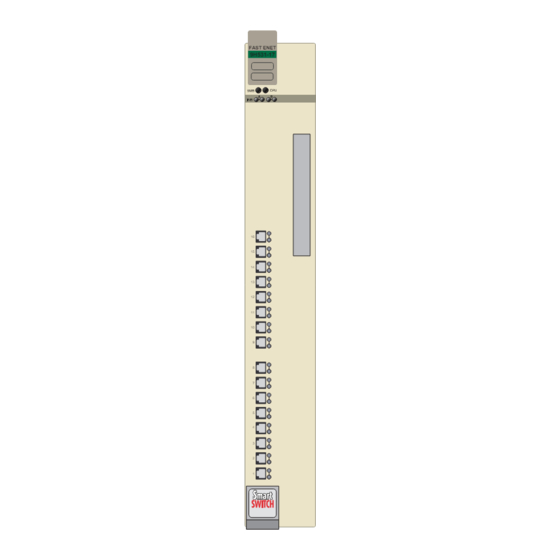
Introduction The 9H531-17 and 9H532-17, shown in Figure 1-1, are SmartSwitch the SmartSwitch 9000. The 9H531-17 and 9H532-17 are seventeen port switch modules, with sixteen 10BASE-T/100BASE-TX or 100BASE-FX ports and one VHSIM (Very High Speed Interface Module), on the front panel. The VHSIM port accepts either HSIM or VHSIM, multi-technology interface modules. - Page 12 Introduction FAST ENET 9H531-17 FAST ENET 9H532-17 Figure 1-1. The 9H531-17 and 9H532-17...
- Page 13 Introduction Auto-Negotiation - Speed/Duplex Mode The twisted pair ports on the front panel of the 9H532-17 module have the ability to auto-negotiate the type of connection required to provide a link to another device. During Auto-Negotiation, two devices automatically exchange information “telling”...
- Page 14 Introduction SmartTrunk SmartTrunk, also referred to as SmartTrunking, is Cabletron Systems’ terminology for load balancing or load sharing. SmartTrunk technology provides an easy-to-implement mechanism to group, or aggregate, multiple links of any technology together to scale the backbone bandwidth beyond the limitations of a single link.
- Page 15 Introduction Cabletron Systems RMON Actions is a vendor-specific extension of RMON and provides the ability to set an “Action” on any SNMP MIB variable. The Action can be triggered by setting an RMON Event and/or Alarm. An example of an Action would be to turn off a MIB-2 interface if a broadcast threshold is crossed.
- Page 16 17 support a wide variety of industry standard MIBs including RFC 1573 (MIB II), RFC 1271 (RMON), RFC 1493 (Bridge MIB), RFC 1354 (FIB MIB), and RFC 1190 (Path MTU Discovery). A full suite of Cabletron Systems Enterprise MIBs provide a wide array of statistical information to enhance troubleshooting. For information about how to extract and compile individual MIBs, contact Cabletron Systems.
-
Page 17: Related Manuals
The 9H531-17 and 9H532-17 modules and the SmartSwitch 9000 chassis have an internal clock that can maintain the time and date beyond the year 1999. Related Manuals The Cabletron Systems manuals listed below should be used to supplement the procedures and technical data contained in this manual. SmartSwitch 9000 Installation Guide SmartSwitch 9000 9C300-1 Environmental Module User’s Guide... -
Page 18: Getting Help
• A description of any action(s) already taken to resolve the problem (e.g., changing mode switches, rebooting the unit, etc.) • The serial and revision numbers of all involved Cabletron Systems products in the network • A description of your network environment (layout, cable type, etc.) •... -
Page 19: Chapter 2 Installing The Smartswitch 9000 Module
DO NOT install the module. Contact Cabletron Systems immediately. Installing an HSIM or VHSIM You can install an HSIM or VHSIM in any Cabletron Systems device that supports HSIMs and VHSIMs. Refer to the release notes for the version of firmware running on the Cabletron Systems device to ensure that the HSIM or VHSIM is supported. -
Page 20: User Accessible Components
Installing the SmartSwitch 9000 Module 2. Attach the antistatic wrist strap (refer to the instructions outlined on the antistatic wrist strap package). 3. Unlock the top and bottom plastic locking tabs of the module faceplate. 4. Slide out the module, and place it on its side with the internal components facing up. - Page 21 DIP Switch Figure 2-1. User-Accessible Components Installing the SmartSwitch 9000 Module SMB-1 PROM i960 Processor 32 MB DRAM VHSIM Connector HSIM Connector Flash SIMM Socket Boot PROM...
- Page 22 Installing the SmartSwitch 9000 Module An eight-position DIP switch is located on the module card as shown in Figure 2-1. The function of the switches are listed in Table 2-1. See the Cautions at the end of this table. Switch Table 2-1.
-
Page 23: Using Dip Switch 6
1. Caution: Do not toggle Switch 8 unless you intend to reset the user- configured passwords to their factory default settings. 2. Caution: Do not toggle Switch 7 unless you intend to reset the user CAUTION parameters to the factory default settings. Using DIP Switch 6 The purpose of DIP switch 6 is to force a Flash download from a BootP server through the EM-EPIM. -
Page 24: Installing The Module Into The Smartswitch 9000 Chassis
Installing the SmartSwitch 9000 Module Installing the Module into the SmartSwitch 9000 Chassis To install the SmartSwitch 9000 module, follow the steps below: The INB Terminator Modules must be installed on the rear of the fourteen slot NOTE chassis before powering up this module. The INB Terminator Modules are not required on the six slot chassis. - Page 25 Metal Back-Panel Ensure that the circuit card is between the card guides. Lock down the top and bottom plastic tabs at the same time, applying even pressure. Figure 2-2. Installing the 9H531-17 and 9H532-17 Modules Installing the SmartSwitch 9000 Module F L N K F L N K F L N K...
-
Page 26: The Reset Switch
Installing the SmartSwitch 9000 Module The Reset Switch The Reset switch is located under the top plastic tab as shown in Figure 2-3. Use the reset switch to reset the module’s processor, shutdown (power down) the module, and/or restart the module. •... -
Page 27: Cabling Requirements
IEEE 802.3u 100BASE-TX Fast Ethernet network requirements for the devices to operate at 100 Mbps. Refer to the Cabletron Systems Cabling Guide for details. 100BASE-FX Network The 9H531-17 supports 100BASE-FX. When connecting a 100BASE-FX segment to any of the front panel ports, ensure that the network meets the optical performance requirements for 100BASE-FX IEEE 802.3u standard. - Page 28 Installing the SmartSwitch 9000 Module 2-10...
-
Page 29: Chapter 3 Technical Overview
Technical Overview SmartSwitch Architecture The SmartSwitch Architecture of the 9H531-17 and 9H532-17 modules, as shown in Figure 3-1, are configurable for one of two modes of operation: traditional IEEE 802.1 switching, or SecureFast switching. The modules support only one of these modes of operation at any one time. - Page 30 Technical Overview VHSIM Front Octal Panel Ports (24) Octal DC/DC Converter SMB 1 Diagnostic i960 Controller Processor SMB 10 Ethernet Controller ASIC Smart Switch Fabric ASIC Figure 3-1. Block Diagram SmartSwitch 9000 Backplane 48 Volt Power Bus...
-
Page 31: System Management Buses
System Management Buses There are two management channels within the SmartSwitch 9000 system: the SMB-1 and the SMB-10. These buses provide out-of-band management and inter-module management communication. SMB-1 Bus The SMB-1 is a 1 Mbps management bus located within the SmartSwitch 9000. This bus is utilized by all diagnostic controllers in the system including connectivity modules, power supply modules and the environmental module. -
Page 32: System Diagnostic Controller
Technical Overview System Diagnostic Controller This diagnostic controller is composed of a Z-80 microprocessor and its supporting logic. The diagnostic controller is designed to control the power-up sequencing of modules, monitor the 9H531-17 and 9H532-17 input and output power parameters, keep watch over the main host processor, as well as monitor the temperature and control the SMB LANVIEW diagnostic LED. -
Page 33: Lanview Leds
LANVIEW LEDs The front panel LANVIEW LEDs indicate the status of the module and may be used as an aid in troubleshooting. Figure 4-1 shows the LANVIEW LEDs of the 9H531-17 and 9H532-17 modules. The LED Mode Switch The 9H532-17 has an LED mode switch, located on the front panel, that allows the user to change the function of the switch port LEDs. - Page 34 LANVIEW LEDs INB Receive Figure 4-1. The LANVIEW LEDs (9H532-17 shown) and LED Mode Switch The functions of the two System Status LEDs, System Management Bus (SMB) and the CPU, are listed in Table 4-1. LED Color Green Yellow Yellow (Flashing) Yellow/Green Red (Flashing) FAST ENET...
- Page 35 The functions of the INB transmit LED are listed in Table 4-2. LED Color Green (Flashing) Data activity Yellow (Flashing) Port in standby state Red (Flashing) Collision Fault No activity, Port disabled The functions of the INB receive LED are listed in Table 4-3. LED Color Green (Flashing) Link, Port disabled...
- Page 36 LANVIEW LEDs LED Color Green Yellow (Flashing) Red (Flashing) The functions of the Speed and Full Duplex LEDs are list in Table 4-6 and Table 4-7. These LED indications are only valid when the LED MODE switch is in the DPX-SPD position. LED Color Green Yellow...
-
Page 37: Chapter 5 Specifications
Specifications Technical Specifications CPUs PowerPC Intel i960 RISC-based microprocessor Memory 8 MB Flash Memory (expandable to 16 MB) 32 MB DRAM (local) 4 MB Memory (Shared) Network Interface 16 RJ45 Unshielded Twisted Pair ports (9H532-17) - 10BASE-T/100BASE-TX 16 MT-RJ multimode fiber ports (9H531-17) - 100BASE-FX Performance Module Switch Fabric bandwidth 3.3 Gbps Module Throughput... -
Page 38: Regulatory Compliance
Specifications Regulatory Compliance It is the responsibility of the person who sells the system to which the module will be a part to ensure that the total system meets allowed limits of conducted and radiated emissions. CAUTION This equipment meets the following safety and electromagnetic compatibility (EMC) requirements: Safety Electromagnetic Compatibility (EMC)
Need help?
Do you have a question about the Expansion module 9H532-17 and is the answer not in the manual?
Questions and answers