
Related Manuals for Cabletron Systems MMAC-Plus 9G536-04


Summary of Contents for Cabletron Systems MMAC-Plus 9G536-04
- Page 1 SmartSwitch 9000 9G536-04 Four Port Gigabit Ethernet Module User’s Guide 9033049-01...
-
Page 3: Fcc Notice
Notice NOTICE Cabletron Systems reserves the right to make changes in specifications and other information contained in this document without prior notice. The reader should in all cases consult Cabletron Systems to determine whether any such changes have been made. The hardware, firmware, or software described in this manual is subject to change without notice. - Page 4 Notice CABLETRON SYSTEMS, INC. PROGRAM LICENSE AGREEMENT IMPORTANT: THIS LICENSE APPLIES FOR USE OF PRODUCT IN THE FOLLOWING GEOGRAPHICAL REGIONS: CANADA MEXICO CENTRAL AMERICA SOUTH AMERICA BEFORE OPENING OR UTILIZING THE ENCLOSED PRODUCT, CAREFULLY READ THIS LICENSE AGREEMENT. This document is an agreement (“Agreement”) between You, the end user, and Cabletron Systems, Inc. (“Cabletron”) that sets forth your rights and obligations with respect to the Cabletron software program (“Program”) in the package.
- Page 5 Notice EXCLUSION OF WARRANTY. Except as may be specifically provided by Cabletron in writing, Cabletron makes no warranty, expressed or implied, concerning the Program (including its documentation and media). CABLETRON DISCLAIMS ALL WARRANTIES, OTHER THAN THOSE SUPPLIED TO YOU BY CABLETRON IN WRITING, EITHER EXPRESS OR IMPLIED, INCLUDING BUT NOT LIMITED TO IMPLIED WARRANTIES OF MERCHANTABILITY AND FITNESS FOR A PARTICULAR PURPOSE, WITH RESPECT TO THE PROGRAM, THE ACCOMPANYING WRITTEN MATERIALS, AND ANY ACCOMPANYING HARDWARE.
- Page 6 Notice export to Country Groups D:1 or E:2 the direct product of the plant or a major component thereof, if such foreign produced direct product is subject to national security controls as identified on the U.S. Commerce Control List or is subject to State Department controls under the U.S. Munitions List.
- Page 7 Notice EXPORT REQUIREMENTS. You understand that Cabletron and its Affiliates are subject to regulation by agencies of the U.S. Government, including the U.S. Department of Commerce, which prohibit export or diversion of certain technical products to certain countries, unless a license to export the product is obtained from the U.S. Government or an exception from obtaining such license may be relied upon by the exporting party.
-
Page 8: Safety Information
Notice SAFETY INFORMATION CLASS 1 LASER TRANSCEIVERS THE GPIM-09 MODULE USES CLASS 1 LASER TRANSCEIVERS. READ THE FOLLOWING SAFETY INFORMATION BEFORE INSTALLING OR OPERATING THESE MODULES. The Class 1 laser transceivers use an optical feedback loop to maintain Class 1 operation limits. This control loop eliminates the need for maintenance checks or adjustments. -
Page 9: Declaration Of Conformity
Notice DECLARATION OF CONFORMITY Application of Council Directive(s): 89/336/EEC 73/23/EEC Manufacturer’s Name: Cabletron Systems, Inc. Manufacturer’s Address: 35 Industrial Way PO Box 5005 Rochester, NH 03867 European Representative Name: Mr. J. Solari European Representative Address: Cabletron Systems Limited Nexus House, Newbury Business Park London Road, Newbury Berkshire RG14 2PZ, England Conformance to Directive(s)/Product Standards:... - Page 10 Notice viii...
-
Page 11: Table Of Contents
Contents Chapter 1 Introduction Features........................... 1-1 Related Manuals......................1-7 Getting Help ........................1-7 Chapter 2 Installing the SmartSwitch 9000 Module Unpacking the Module....................2-1 User Accessible Components ..................2-1 Using DIP Switch 6 ....................2-4 Installing GPIMs ......................2-4 Installing the Module into the SmartSwitch 9000 Chassis........2-6 The Reset Switch ...................... - Page 12 Contents Physical........................5-2 Dimensions ...................... 5-2 Weight....................... 5-2 Environment ....................5-2 GPIM-01 SpeciÞcations (1000Base-SX)..............A-1 GPIM-09 SpeciÞcations (1000Base-LX) ..............A-2 Physical and Environmental SpeciÞcations .............A-2 Regulatory Compliance....................A-3...
-
Page 13: Chapter 1 Introduction
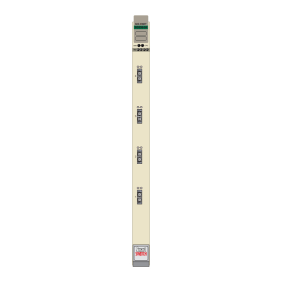
Chapter 1 Introduction The 9G536-04 shown in Figure 1-1, is a Gigabit Ethernet Switch module for Cabletron Systems SmartSwitch 9000 chassis. The 9G536-04 has four Gigabit Interfaces. The 9G536-04 can be used to connect individual high-bandwidth user devices, such as workstations, or to provide a central switching point for multiple Gigabit Ethernet segments. - Page 14 Introduction GIG ENET 9G536-04 Figure 1-1. The 9G536-04...
- Page 15 Introduction Auto-Negotiation The GPIM ports on the front panel of the 9G536-04 module have the ability to auto-negotiate the type of connection required to provide a link to another device. During Auto-Negotiation, two devices automatically exchange information ÒtellingÓ each other what their operating capabilities are. The Auto-Negotiation feature targets the maximum capabilities that can be reached between the two devices.
- Page 16 Introduction For information on SmartTrunk conÞguration, refer to the SmartTrunk UserÕs Guide. NOTE Management Management of the 9G536-04 modules and SmartSwitch chassis and any optional equipment is accomplished using the Local Management application or remote SNMP management stations. Local Management is accessible through the RS232 COM port on the front panel using a local VT100 terminal, or a remote VT100 terminal via a modem connection, and in-band via a Telnet connection.
- Page 17 Introduction errors, to be copied and sent to an analyzer or RMON probe. The analyzer or RMON probe will see the data as if it is directly connected to the LAN segment of the source port. Flow Control Flow Control is a method of managing the ßow of frames between two devices. It ensures that a transmitting device does not overwhelm a receiving device with data.
- Page 18 Introduction operation), the switch functions as an 802.1D switch. When until VLANs are conÞgured, it operates as an 802.1Q switch. Standards Compatibility The 9G536-04 is fully compliant with the IEEE 802.3z, 802.3x, 802.1Q, and 802.1p standards. The 9G536-04 provides IEEE 802.1D Spanning Tree Algorithm (STA) support to enhance the overall reliability of the network and protect against ÒloopÓ...
-
Page 19: Related Manuals
Introduction Related Manuals The manuals listed below should be used to supplement the procedures and technical data contained in this manual. SmartSwitch 9000 Installation Guide SmartSwitch 9000 9C300-1 Environmental Module UserÕs Guide SmartSwitch 9000 9C214-1 AC Power Supply UserÕs Guide SmartSwitch 9000 9X5XX Series Local Management UserÕs Guide Cabling Guide Ethernet Technology Guide... - Page 20 Introduction Before calling Cabletron Systems, have the following information ready: ¥ Your Cabletron Systems service contract number ¥ A description of the failure ¥ A description of any action(s) already taken to resolve the problem (e.g., changing mode switches, rebooting the unit, etc.) ¥...
-
Page 21: Installing The Smartswitch 9000 Module
Chapter 2 Installing the SmartSwitch 9000 Module This module uses GPIMs for front panel connections. They are not shipped with the module and must be purchased separately. Only qualiÞed personnel should perform installation procedures. Unpacking the Module 1. Carefully remove the module from the shipping box. (Save the box and packing materials in the event the module must be reshipped.) 2. - Page 22 Installing the SmartSwitch 9000 Module SMB-1 PROM i960 Processor 32 MB DRAM Flash SIMM Socket Boot PROM DIP Switch Figure 2-1. User-Accessible Components...
- Page 23 Installing the SmartSwitch 9000 Module An eight-position DIP switch is located on the module card as shown in Figure 2-1. The function of the switches are listed in Table 2-1. See the Cautions at the end of this table. Table 2-1. Function of DIP Switch Switch Function Description...
-
Page 24: Using Dip Switch 6
Installing the SmartSwitch 9000 Module Using DIP Switch 6 The purpose of DIP switch 6 is to force a Flash download from a BootP server through the EM-EPIM. The Þrst step in this process is to conÞgure the BootP server. ConÞgurations of BootP servers can differ from platform to platform and from one operating system to another. - Page 25 Installing the SmartSwitch 9000 Module Insertion End 20-pin connector Network Connection End 2549_04 Figure 2-2. GPIM 4. Gently insert the GPIM (20-pin connector side) through the GPIM opening of the SmartSwitch 9000 module, as shown in Figure 2-3. The door folds to the left and the slides engage the sides of the GPIM.
-
Page 26: Installing The Module Into The Smartswitch 9000 Chassis
Installing the SmartSwitch 9000 Module Installing the Module into the SmartSwitch 9000 Chassis To install the SmartSwitch 9000 module, follow the steps below: The INB Terminator Modules must be installed on the rear of the fourteen slot NOTE chassis before powering up this module. The INB Terminator Modules are not required on the six slot chassis. - Page 27 Installing the SmartSwitch 9000 Module FLNK FLNK FLNK FLNK FLNK Jack for ESD wrist strap Metal Back-Panel Circuit Card Card Guides Warning: Ensure that the circuit card is between the card guides. Lock down the top and bottom plastic tabs at the same time, applying even pressure.
-
Page 28: The Reset Switch
Installing the SmartSwitch 9000 Module The Reset Switch The Reset switch is located under the top plastic tab as shown in Figure 2-5. Use the reset switch to reset the moduleÕs processor, shutdown (power down) the module, and/or restart the module. ¥... -
Page 29: Technical Overview
Chapter 3 Technical Overview SmartSwitch Architecture The SmartSwitch Architecture of the 9G536-04 module, as shown in Figure 3-1, is conÞgurable for one of two modes of operation: traditional IEEE 802.1 switching, or SecureFast switching. The module supports only one of these modes of operation at any one time. -
Page 30: System Management Buses
Technical Overview SmartSwitch 9000 Backplane DC/DC 48 Volt Converter Gigabit Power Bus Port SMB 1 Diagnostic i960 Controller Processor SMB 10 Ethernet Controller Gigabit ASIC Port Smart Switch Fabric ASIC Gigabit Port Gigabit Port Figure 3-1. Block Diagram System Management Buses There are two management channels within the SmartSwitch 9000 system: the SMB-1 and the SMB-10. -
Page 31: Smb-1 Bus
Technical Overview SMB-1 Bus The SMB-1 is a 1 Mbps management bus located within the SmartSwitch 9000. This bus is utilized by all diagnostic controllers in the system including connectivity modules, power supply modules and the environmental module. The SMB-1 transports inter-chassis information between system components, such as power and environmental information, as well as diagnostic messages. -
Page 32: Dc/Dc Converter
Technical Overview DC/DC Converter The DC/DC converter converts the 48 VDC on the system power bus to the necessary operating voltages for its host network services module. The diagnostic controller monitors and controls the operation of the DC/DC converter. INB Interface Each module attaches to both INB A and INB B and has two INB ASICs. -
Page 33: Lanview Leds
Chapter 4 LANVIEW LEDs The front panel LANVIEW LEDs indicate the status of the module and may be used as an aid in troubleshooting. Figure 4-1 shows the LANVIEW LEDs of the 9G536-04 module. System Status GIG ENET 9G536-04 INB Transmit GPIM Receive GPIM Transmit INB Receive... - Page 34 LANVIEW LEDs The functions of the two System Status LEDs, System Management Bus (SMB) and the CPU, are listed in Table 4-1. Table 4-1. System Status (SMB and CPU) LEDs LED Color State Description Green Functional Fully operational Yellow Testing Power-up testing Yellow (Flashing) Crippled...
- Page 35 LANVIEW LEDs The functions of the GPIM transmit LEDs are listed in Table 4-4. Table 4-4. GPIM Transmit LEDs LED Color State Green (Flashing) Activity, port enabled Yellow (Flashing) Port in standby Red (Flashing) Transmit fault Diagnostic failure No activity, port enabled The functions of the GPIM receive LEDs are listed in Table 4-5.
- Page 36 LANVIEW LEDs...
-
Page 37: Chapter 5 Specifications
Chapter 5 Specifications Technical Specifications PowerPC Intel i960 RISC based microprocessor Memory 8 MB Flash Memory (expandable to 16 MB) 32 MB DRAM (local) 4 MB Memory (shared) Network Interface Four Cabletron Systems GPIMs Performance Module Switch Fabric bandwidth 3.3 Gbps Module Throughput 2.2 Mpps Source Address Table... -
Page 38: Regulatory Compliance
Specifications Regulatory Compliance It is the responsibility of the person who sells the system to which the module will be a part to ensure that the total system meets allowed limits of conducted and radiated emissions. CAUTION This equipment meets the following safety and electromagnetic compatibility (EMC) requirements: Safety UL 1950, CSA C22.2 No. - Page 39 Appendix A GPIM Specifications This appendix lists the speciÞcations and regulatory requirements for GPIMs and the media they use. Cabletron Systems reserves the right to change these speciÞcations at any time without notice. The available GPIM options include the GPIM-01 and GPIM-09. The GPIM-01 and GPIM-09 are both Þber optic devices with an SC connector.
- Page 40 GPIM Specifications GPIM-09 Specifications (1000Base-LX) Table A-3. GPIM-09 Optical Specifications 62.5 µm MMF 50 µm MMF 10 µm MMF Transmit Power -11.5 dBm -11.5 dBm -9.5 dBm (minimum) Receive Sensitivity -20 dBm -20 dBm -20 dBm Link Power Budget 8.5 dBm 8.5 dBm 10.5 dBm Table A-4.
-
Page 41: Regulatory Compliance
Regulatory Compliance Regulatory Compliance The GPIMs meet the following safety and electromagnetic compatibility (EMC) requirements: Table A-7. Regulatory Compliance FDA CDRH 21-CFR 1040 Class 1, Eye Safety (fiber GPIMs only) IEC 825 Issue 1 1993:11 Class 1, CENELEC EN 60825 Class 1... - Page 42 GPIM Specifications...
Need help?
Do you have a question about the MMAC-Plus 9G536-04 and is the answer not in the manual?
Questions and answers