Table of Contents
Advertisement
Quick Links
Advertisement
Table of Contents

Related Manuals for Cabletron Systems MMAC-Plus 9H423-26


Summary of Contents for Cabletron Systems MMAC-Plus 9H423-26
- Page 1 SmartSwitch 9000 9H423-26 User’s Guide 9032242-02...
- Page 3 Notice Notice Cabletron Systems reserves the right to make changes in specifications and other information contained in this document without prior notice. The reader should in all cases consult Cabletron Systems to determine whether any such changes have been made. The hardware, firmware, or software described in this manual is subject to change without notice.
-
Page 4: Fcc Notice
Notice FCC Notice This device complies with Part 15 of the FCC rules. Operation is subject to the following two conditions: (1) this device may not cause harmful interference, and (2) this device must accept any interference received, including interference that may cause undesired operation. NOTE: This equipment has been tested and found to comply with the limits for a Class A digital device, pursuant to Part 15 of the FCC rules. -
Page 5: Declaration Of Conformity
DECLARATION OF CONFORMITY Application of Council Directive(s): Manufacturer’s Name: Manufacturer’s Address: European Representative Name: European Representative Address: Conformance to Directive(s)/Product Standards: Equipment Type/Environment: We the undersigned, hereby declare, under our sole responsibility, that the equipment packaged with this notice conforms to the above directives. Manufacturer Mr. -
Page 6: Safety Information
Notice Safety Information CLASS 1 LASER TRANSCEIVERS The 9H423-26 is a Class 1 Laser Product The 9H423-26 uses a Class 1 Laser transceiver. Read the following safety information before installing or operating these adapters. The Class 1 laser transceivers use an optical feedback loop to maintain Class 1 operation limits. -
Page 7: Table Of Contents
Getting Help ... 1-6 Chapter 2 Installing the 9H423-26 Module Unpacking the Module... 2-1 User-Accessible Components... 2-1 Setting the Module DIP Switch ... 2-2 Installing the Module in the SmartSwitch 9000 Chassis ... 2-4 The Reset Switch ... 2-6 Chapter 3 Operation FENIB... - Page 8 Contents Chapter 5 Specifications Technical Specifications ... 5-1 CPU ... 5-1 Memory ... 5-1 Standards... 5-1 Network Interfaces ... 5-1 Safety... 5-2 Service ... 5-2 Physical ... 5-2 Dimensions ... 5-2 Weight ... 5-2 Environment ... 5-3 Appendix A 9H423-26 Cabling Requirements Overview ...A-1 Fast Ethernet Standard Requirements...A-2 100BASE-TX ...A-2...
-
Page 9: Chapter 1 Introduction
Architecture. This module can operate in two modes: either as a 26-port Ethernet traditional switch (using 802.1d standards) with a high speed backbone connection, or as a SecureFast switch (SFS) with 26 Ethernet connections. Each port can be configured to operate in the full duplex mode. This configuration allows each 100BASE-T port to provide a full 200 Mbps. -
Page 10: Features
Spanning Tree, RMON, and MIB support, within a scalable RISC-Based architecture. Fast Packet Switching The 9H423-26 module incorporates a hardware-based switch design referred to as the SmartSwitch ASIC, a collection of custom ASICs designed specifically for high-speed switching. Because all frame translation, address lookups, and forwarding decisions are performed in hardware, these modules can obtain a throughput performance of greater than 750K pps. - Page 11 Auto-negotiation The auto-negotiation feature (available only with the 100BASE-T RJ21 ports) allows the module to automatically use the fastest rate supported by the device at the other end (either 10 Mbps or 100 Mbps at either half or full duplex). To negotiate duplex, both the 9H423-26 and the attached device must be configured for auto-negotiation.
- Page 12 Introduction The 9H423-26 module attaches to INB-B of the SmartSwitch 9000 Backplane. The INB backplane is designed to transport fixed-length data blocks between modules in the SmartSwitch 9000 using an INB Time Division Multiplexing (ITDM) design. The SmartSwitch 9000 INB bus delivers 2.5 Gbps of true data bandwidth with all control and management communication being serviced on the 8-bit out-of-band bus.
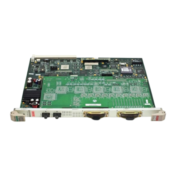
- Page 13 FAST ENET 9H423-26 FAST ENET Figure 1-1. The 9H423-26 Module Introduction...
-
Page 14: Related Manuals
Introduction Related Manuals The Cabletron Systems manuals listed below should be used to supplement the procedures and technical data contained in this manual. SmartSwitch 9000 Installation Guide SmartSwitch 9000 9C300-1 Environmental Module User’s Guide SmartSwitch 9000 9C214-1 AC Power Supply User’s Guide SmartSwitch 9000 Local Management User’s Guide INB Terminator Modules Installation Guide Getting Help... -
Page 15: Installing The 9H423-26 Module
User-Accessible Components Figure 2-1 shows the various components that can be accessed by users. These consist of an eight-position dip switch (explained in the next section), replaceable PROMs, and sockets for memory and flash upgrades. These can be used for future upgrades. -
Page 16: Setting The Module Dip Switch
The DIP switch on the 9H423-26 module (Figure 2-1 ), is an eight-switch DIP located near the left, bottom corner of the module. Each switch is set according to the functions described in Table 2-1. If switch settings are changed, the processor on the module must be reset, using the reset switch or repowering the module, for changes to take effect. - Page 17 Reserved Reserved Reserved Reserved Caution: Do not toggle Switch 8 unless you intend to reset the user-configured passwords to the factory default settings. CAUTION Caution: Do not toggle Switch 7 unless you intend to reset the user-entered parameters to the factory default settings.
-
Page 18: Installing The Module In The Smartswitch 9000 Chassis
Installing the 9H423-26 Module Installing the Module in the SmartSwitch 9000 Chassis To install the 9H423-26 module in the SmartSwitch 9000 chassis, follow the steps below: 1. Remove the blank panel covering the slot in which the module will be mounted. - Page 19 Metal Back-Panel Module Guides Warning: Ensure that the circuit card is between the card guides. Lock down the top and bottom plastic tabs at the same time, applying even pressure. Figure 2-2. Installing the Module Installing the 9H423-26 Module Plastic Tab Jack for ESD Wrist Strap Module...
-
Page 20: The Reset Switch
Installing the 9H423-26 Module The Reset Switch The Reset switch is located on the front panel, under the top plastic tab as shown in Figure 2-3. It serves three functions: resetting the i960 processor, shutting down the module, or restarting the module. -
Page 21: Chapter 3 Operation
Chapter 3 Operation The 9H423-26 module is a twenty-seven port device. Two front panel RJ21 connectors support twenty-four 100BASE-T ports, along with two SC fiber connectors that support two 100BASE-FL ports. Each of these twenty-six ports is a separate collision domain, while the 27th port connects to INB-B. As shown in Figure 3-1, Fast Ethernet Network Interface Blocks (FENIBs) convert data packets received from any of the 100BASE ports into a canonical frame format before forwarding to the SmartSwitch ASIC, while the Internal Network... -
Page 22: Fenib
The FENIB also converts data packets from the common canonical format back to Fast Ethernet data packets for transmission out front panel ports. FENIB FENIB i960 Processor Smart Switch ASIC Figure 3-1. Packet Flow for the 9H423-26 SMB 1 Diagnostic Controller SMB 10... -
Page 23: Smartswitch Asic
INB backplane, and LAN/WAN interfaces on the front panel of SmartSwitch 9000 modules. The SmartSwitch ASIC can operate in two modes: as a traditional switch or as a SecureFast switch. Traditional Switch When operating as a traditional switch, the SmartSwitch ASIC makes filtering/ forwarding decisions based on Destination Address (DA), with standard IEEE 802.1d learning. -
Page 24: Vlan Domains
VLAN domains consist of groups of interconnected VLAN switches separated by routing devices. Figure 3-3 shows such an arrangement. Each group of switches constitutes a VLAN domain. VLAN Domain SFS Network VLAN Switch VLAN Switch VLAN Switch LAN A SFS Network LAN B Figure 3-2. -
Page 25: Fully Meshed Vlan Domains
The circuit is set up, data is transferred, and the circuit is torn down. Switches switch packets at the MAC layer and allow connectivity of endpoints via Access Ports based on VLAN mappings. The first packet is routed, the remaining packets are then switched along the same path. -
Page 26: I960 Core
Operation i960 Core The i960 core provides the SNMP protocol stacks, to support industry-standard MIBs. Additionally, Cabletron enterprise extension MIBs are supported for each media type. Advanced management services, such as the Distributed LAN Monitor, telnet and network address to MAC address mapping, are also provided by the i960 core. -
Page 27: Smb-10 Bus
SMB-10 Bus The SMB-10 is a 10 Mbps management bus located within the SmartSwitch 9000. This bus is used for inter-chassis communication of modules as well as serving as a side-band management channel into the SmartSwitch 9000. The SMB-10 is externalized from the chassis via an optional Ethernet Port Interface Module (EPIM) located on the front of the Environmental Module. -
Page 28: Itdm Arbitration Levels
Operation Arbitration for the backplane is accomplished in the INB Time Division Multiplexing (ITDM) logic. The arbitration is a three-level scheme that ensures that no one can get the backplane for more than one time slice at a time. The ITDM RAM contains 256 4-bit locations. This RAM is used to hold slot numbers of modules participating in INB backplane arbitration. -
Page 29: Monarch/Slave Smartswitch 9000 Modules
Operation Monarch/Slave SmartSwitch 9000 Modules All modules in an SmartSwitch 9000 chassis that transfer packets across the INB backplane have identical INB interfaces. However, one of them has to be selected to perform the backplane arbitration. The lowest slot number module will automatically be selected as the arbitrator. - Page 30 Operation 3-10...
-
Page 31: Lanview Leds
LANVIEW LEDs The front panel LANVIEW LEDs indicate the status of the module and may be used as an aid in troubleshooting. Shown in Figure 4-1 are the LANVIEW LEDs of the 9E423-26 module. INB Receive Transmit FAST ENET System Status 9H423-26 INB Transmit FAST ENET... - Page 32 LANVIEW LEDs The functions of the two System Status LEDs, System Management Bus (SMB) and CPU (Central Processing Unit), are listed in Table 4-1. Table 4-1. System Status (SMB and CPU) LEDs LED Color State Green Functional Yellow Testing Yellow (Blinking) Crippled Yellow/Green Booting...
- Page 33 The functions of the Port Receive LEDs are listed in Table 4-4 LED Color Green Link, no activity port enabled Green (Blinking) Link, port disabled Yellow (Flashing) Link, activity, port enabled (flashing to steady on indicates rate) Fault No link, (port disabled) The functions of the Port Transmit LEDs are listed in Table 4-5.
- Page 34 LANVIEW LEDs...
-
Page 35: Chapter 5 Specifications
Specifications Technical Specifications Intel i960 RISC based microprocessor Memory 4 Mb Local RAM (expandable to 32 MB) 4 Mb Flash Memory (expandable to 32 MB) 2 Mb Packet RAM 16 Mb DRAM (expandable to 48 MB) Standards IEEE 802.1D IEEE 802.3U 100BASE-T IEEE 802.3U 100BASE-FX Network Interfaces 2 fixed RJ21 connectors... -
Page 36: Safety
Specifications Safety It is the responsibility of the person who sells the system to which the module will be a part to ensure that the total system meets allowed limits of conducted and radiated emissions. CAUTION This equipment meets the safety requirements of UL 1950 CSA C22.2 No. -
Page 37: Environment
Environment Operating Temperature: Storage Temperature: Relative Humidity 5° to 40° C (41° to 104° F) -30° to 90° C (-22° to 164° F) 5% to 95% (non-condensing) Specifications... - Page 38 Specifications...
-
Page 39: Appendix A 9H423-26 Cabling Requirements
9H423-26 Cabling Requirements To achieve the highest possible performance from your 9H423-26, proper cabling assemblies and connector hardware for a high speed Fast Ethernet connection are required. This appendix reviews the 9H423-26 connector types and explains the proper mating cabling assemblies. Overview The 9H423-26 supports data rates up to 100 Mbps, requiring cables and connecting hardware that can physically transmit signals at that rate without... -
Page 40: Fast Ethernet Standard Requirements
9H423-26 Cabling Requirements Fast Ethernet Standard Requirements 100BASE-TX The IEEE 802.3u (Fast Ethernet specification) specifies for 100BASE-TX to use either two pair 100 ohm Category 5 unshielded twisted pair (UTP) cable or 2 pair 150 ohm shielded twisted pair (STP) cable. This module utilizes Category 5 100 ohm UTP Cabling systems. - Page 41 Table A-1. RJ45 PINOUT RJ45 Pin # Wire Color Code White/Blue Blue White/Orange Orange White/Green Green White/Brown Brown 8 7 6 5 4 3 2 1 Figure A-2. RJ45 Plug Pinout On the 9H423-26, the connecting hardware is not an eight-wire RJ45, but a 50-wire, 25-pair RJ21 (Figure A-3).
- Page 42 9H423-26 Cabling Requirements The RJ21 connector is a D-shaped metal housing that is wired and crimped to a 25-pair UTP cable (Figure A-4). The RJ21 connector has one pair that is unconnected: pair 25, which corresponds to pins 25 and 50 on the RJ21. It is left floating. This “Telco” connector utilizes the standard EIA/TIA 568A wiring scheme.
- Page 43 Table A-2. RJ21 PINOUT RJ21 Pin # Wire Color Code White/Blue Blue/White White/Orange Orange/White White/Green Green/White White/Brown Brown/White White/Slate Slate/White Red/Blue Blue/Red Red/Orange Orange/Red Red/Green Green/Red Red/Brown Brown/Red Red/Slate Slate/Red Black/Blue Blue/Black Black/Orange Orange/Black 9H423-26 Cabling Requirements Pair Signal Port...
- Page 44 9H423-26 Cabling Requirements RJ21 Pin # Table A-2. RJ21 PINOUT (continued) Wire Color Code Pair Black/Green Green/Black Black/Brown Brown/Black Black/Slate Slate/Black Yellow/Blue Blue/Yellow Yellow/Orange Orange/Yellow Yellow/Green Green/Yellow Yellow/Brown Brown/Yellow Yellow/Slate Slate/Yellow Violet/Blue Blue/Violet Violet/Orange Orange/Violet Violet/Green Green/Violet Violet/Brown Brown/Violet Violet/Slate Slate/Violet Signal Port...
-
Page 45: 100Base-Fx
The colors in bold designate the primary color of the wire. For example, pin 26 connects to a NOTE wire that is primarily white with blue stripes and pin 1’s wire is underlying blue with white stripes. However, because Category 5 has more “twists” than Category 3, vendors might manufacture the twisted pairs with the primary colors only. - Page 46 9H423-26 Cabling Requirements Per TIA/EIA 568A, 100 classifications: Category 1 through Category 5, based on transmission characteristics and performance requirements. Refer to Table A-3. Category (CAT) CAT 1 CAT 2 CAT 3 CAT 4 CAT 5 Physical differences between the various classifications of cable attribute to better performance.
- Page 47 Return Loss (SRL). Refer to Table A-4. To be labeled as Category 5, the following SRL values must be satisfied. Table A-4. UTP Cable SRL Freq. f (MHz) CAT 3 (dB) 1-10 10-16 (f/10) 16-20 20-100 • Attenuation - Attenuation refers to the amount of signal level degradation through a medium.
- Page 48 9H423-26 Cabling Requirements • Near End Crosstalk (NEXT) Loss - The NEXT cites noise and interference within a pair, or more, of conductors where one conductor induces crosstalk on the other. The Near End refers to coupling that takes place when the transmit signal entering the link couples back to the receive conductor pair a that same end of the link;...
-
Page 49: Why Are Cat 5 Connectors Necessary For 100Base-Tx
Why are CAT 5 Connectors Necessary for 100BASE-TX? Similar to the UTP cable itself, the connector hardware plays an important role in the overall performance of the assembly. If an electrical signal travels through a Category 5 cable with little attenuation and then meets an inferior connector, the signal will presently be degraded due to the connector. - Page 50 9H423-26 Cabling Requirements Table A-8. NEXT Loss (Worst Pair Combination) for 100 m Freq (MHz) 31.25 62.5 100.0 • Return Loss - Return Loss is the measure of the degree of impedance matching between cable and connector. A balanced input signal is applied to a connector pair and the reflected signal is measured.
-
Page 51: Fiber Optic Cabling
Fiber Optic Cabling As mentioned previously, the 9H423-26 utilizes 1300 nm, 62.5/125 m fiber. Because it will be primarily used in a ‘backbone cabling’ configuration, the following optical fiber specifications will be stated per this case. (If implementing Horizontal type fiber connections, see TIA/EIA 568A, section 12.2.) The fiber will be multimode graded-index, 62.5/125 m core/cladding diameter. - Page 52 9H423-26 Cabling Requirements A-14...
Need help?
Do you have a question about the MMAC-Plus 9H423-26 and is the answer not in the manual?
Questions and answers