
Subscribe to Our Youtube Channel
Related Manuals for YOKOGAWA WE7281


Summary of Contents for YOKOGAWA WE7281
- Page 1 User's Manual 4-CH, 100 kS/s D/A Module IM 707281-01E 2nd Edition IM 707281-01E 2nd Edition...
- Page 2 • The figures of operation panels that are used in this manual correspond to WE7281. If you are using WE7282, WE7282 will be displayed. • The contents of this manual are subject to change without prior notice as a result of continuing improvements to the instrument’s performance and functions.
-
Page 3: Checking The Contents Of The Package
WE7282 4-CH, 100 kS/s D/A Module (BNC output terminals) When contacting the dealer from which you purchased the instrument, please quote the instrument No. The following is an example of WE7281. The name plate is also at the same position for WE7282. -
Page 4: How To Use This Manual
How to Use This Manual Structure of the Manual This User’s Manual consists of the following five chapters and an index. Chapter Title Description Explanation of Functions Explains the system configuration and functions. Hardware Preparation Explains how to install the module into the measuring station and how to connect the input. - Page 5 IM 707281-01E...
-
Page 6: Table Of Contents
Contents Checking the Contents of the Package ........................2 How to Use This Manual ............................3 Chapter 1 Explanation of Functions Principles of Waveform Generation ..................1-1 System Configuration and Block Diagram ................1-2 Waveforms That Can Be Generated ..................1-3 Waveform Generation in the DC Mode ................... -
Page 7: Chapter 1 Explanation Of Functions
Chapter 1 Explanation of Functions 1.1 Principles of Waveform Generation The 4-CH, 100 kS/s D/A Module WE7281/WE7282 has DC, AG, and FG waveform generation modes. Of the three modes, the operation principles of AG and FG modes are described here. -
Page 8: System Configuration And Block Diagram
1.2 System Configuration and Block Diagram System Configuration The following shows an example in which a 4-CH D/A Module WE7281 is installed in the measuring station and the measuring station is connected to the PC through the optical fiber cable. -
Page 9: Waveforms That Can Be Generated
1.3 Waveforms That Can Be Generated This module has the following three waveform generation modes. One mode is selected and the waveform is generated. : DC signal : Arbitrary waveform : Sine wave, pulse wave, ramp wave, triangular wave, arbitrary wave, and DC signal. -
Page 10: Waveform Generation In The Dc Mode
1.4 Waveform Generation in the DC Mode Setting the Output Conditions You can turn ON/OFF the output and set the output voltage range for each channel. Setting the output voltage range You can select the range from the following list of choices. Setting Possible Output Range Resolution... -
Page 11: Waveform Generation In The Ag Mode
1.5 Waveform Generation in the AG Mode Setting the Output Conditions You can turn ON/OFF the output and set the output voltage range for each channel. Setting the output voltage range You can select the range from the following list of choices. Setting Possible Output Range –1 to 1 V... - Page 12 1.5 Waveform Generation in the AG Mode Selecting the Output Mode One shot Outputs the one-shot waveform of the specified block. Output Output voltage Continuous oscillation Continuously outputs the waveform of the specified block. Output Output voltage One block of waveform Trigger oscillation The waveforms set in the Start block to the End block are sequentially output every time a trigger occurs.
- Page 13 1.5 Waveform Generation in the AG Mode Creating and Loading Arbitrary Waveform Data Data that can be loaded as arbitrary waveform data must be of YOKOGAWA’s propri- etary file format (extension: wvf) or be ASCII data in csv format. Creating arbitrary waveform data Creating a wvf file.
-
Page 14: Waveform Generation In The Fg Mode
1.6 Waveform Generation in the FG Mode Selecting the Output Waveform (Function) Select the output waveform from the following list of choices. You can also select waveform inversion. Sine wave Generates a sine wave with a frequency between 1 mHz and 20 kHz. Inversion Pulse wave The selectable oscillation frequencies range from 1 mHz to 10 kHz. - Page 15 1.6 Waveform Generation in the FG Mode Selecting the Output Mode (Continuous Oscillation/Trigger Oscillation/Gate Oscillation) The following three output modes are available. Continuous oscillation Continuously generates the waveform. Output Output voltage Trigger oscillation Continuously generates the waveform when a trigger occurs. Output Trigger signal Output voltage...
- Page 16 1.6 Waveform Generation in the FG Mode Setting the Output Conditions (Output Frequency, Output Voltage, and Phase) Output frequency When the output waveform is a sine wave, the frequency can be set in the range from 1 mHz to 20 kHz. For all other waveforms, the frequency can be set in the range from 1 mHz to 10 kHz.
- Page 17 1.6 Waveform Generation in the FG Mode Setting Sweeps Selecting the parameter to sweep Select which parameter to sweep from the following list of choices. : Do not sweep Freq : Sweep the frequency Ampl : Sweep the amplitude Duty : Sweep the duty cycle (selectable only for pulse waveform) Freq &...
- Page 18 1.6 Waveform Generation in the FG Mode Selecting the sweep mode Select the sweep mode from the following choices. : Do not sweep Repeat : Sweep continuously Single : Sweep once when a trigger occurs Trigger signal Single&Hold : Perform a single sweep when a trigger occurs, then hold the last value and output a continuous oscillation waveform Trigger signal Hold the...
- Page 19 1.6 Waveform Generation in the FG Mode Arbitrary Waveform Output Data that can be loaded as arbitrary waveform data are as follows. • A file with a [.s16] file extension (Created using the Waveform Editor (707751) that is sold separately) •...
-
Page 20: Other Functions
1.7 Other Functions Input/Output of Bus Trigger Signals You can output a signal that is synchronized to the waveform output (trigger output signal) to the two trigger signal buses (BUSTRG1/BUSTRG2) in the measuring station. The trigger output signal is set to “True” for approximately 160 ns (typical value*). There is a time difference of approximately 12.5 µs (typical value*) between the trigger output signal and the bus trigger signal. -
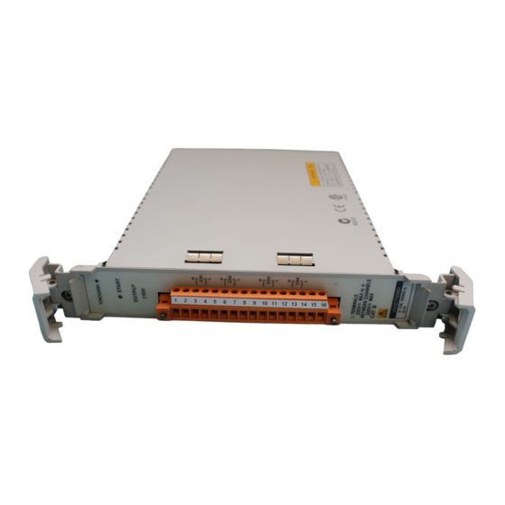
Page 21: Names And Functions Of Sections
1.8 Names and Functions of Sections Front Panel WE7281 START indicator START Lights when the waveform OUTPUT ± 10V is being output. Terminal block Provides 4 channels of output terminals. L TERMINALS 250V MAX to BETWEEN CHANNELS 250V MAX WE7282... -
Page 22: Chapter 2 Hardware Preparation
Chapter 2 Hardware Preparation 2.1 Installing the Module into the Measuring Station Preparing to Install the Module Upon purchasing the measuring station, each slot is covered with a cover plate as shown in the figure below. Verify that the power supply is not connected to the measuring station, then loosen the module attachment screws (2 locations) and remove the cover plate from the slot where the module is going to be installed. - Page 23 2.1 Installing the Module into the Measuring Station The following figure shows an example of WE7281. WE7282 can also be installed or removed in a similar fashion. • When removing the module Ejection lever Module attachment screw Module attachment screw...
-
Page 24: Connecting The Output Signal Wire
2.2 Connecting the Output Signal Wire For WE7281 The output signal wires are connected to the terminal block of the 4-CH, 100 kS/s D/A module. Pin arrangement of the terminal block The output terminal is a clamp type terminal, and the pin arrangement is as follows. - Page 25 Note The maximum length of the cable that is connected to the output connectors of WE7281/WE7282 is 20 m. However, if the cable length exceeds 3 m, undesirable effects such as delay in the rise time of the output waveform or distortion may occur.
-
Page 26: Chapter 3 Software Operation
Chapter 3 Software Operation 3.1 Selecting the Waveform Generation Mode In this section, you will be using the operation panel that appears by double-clicking the module icon in the station list window as shown in the figure below Select the waveform generation mode Selecting the Waveform Generation Mode Select the mode using the [Operation Mode] option button. -
Page 27: Setting The Output Conditions In The Dc Mode
3.2 Setting the Output Conditions in the DC Mode In this section, you will be using the operation panel that appears by double-clicking the module icon in the station list window as shown in the figure below and the trigger operation panel that appears by clicking the Trig tab. - Page 28 3.2 Setting the Output Conditions in the DC Mode Selecting the Trigger Signal Output Source Channel The trigger operation panel shown below is used to set the trigger signal output source channel. Trig tab Select the output channel Click the [Source] button to select the source channel that will be used to output the trigger signal.
-
Page 29: Setting The Output Condition In The Ag Mode
3.3 Setting the Output Condition in the AG Mode In this section, you will be using the operation panel that appears by double-clicking the module icon in the station list window as shown in the figure below and the trigger and Misc operation panels that appear by clicking the Trig and Misc tabs, respectively. - Page 30 3.3 Setting the Output Condition in the AG Mode Setting the Output Timing of the Trigger Signal The trigger operation panel shown below is used to set the output timing. Trig tab Set the output timing of the trigger signal Specify at what position of the output waveform to output the trigger signal in the [Point] entry box.
- Page 31 3.3 Setting the Output Condition in the AG Mode Selecting the number of channels used Select the maximum number of channels used of the waveform to be loaded with the [CH Mode] option button. The choices are shown below. When auto load is used to load waveform data, this number is automatically set to the number of channels used of the waveform data being loaded.
- Page 32 3.3 Setting the Output Condition in the AG Mode 3. The following dialog box appears. Clicking the [OK] button causes the number of channels and blocks of the waveform data to be automatically determined, and the waveform data to be loaded. Note •...
- Page 33 3.3 Setting the Output Condition in the AG Mode 5. Clicking the button to the left of the [OK] button opens the [Open] dialog box. Select a file with extension [*.wvf] or [*.csv] and click the [Open] button. 6. The setup data of the file being loaded appear in a dialog box as shown below. Select the channel and block that are to be loaded in the [Trace Name] and [Block No.] list boxes, respectively.
-
Page 34: Setting The Output Condition In The Fg Mode
3.4 Setting the Output Condition in the FG Mode In this section, you will be using the operation panel that appears by double-clicking the module icon in the station list window as shown in the figure below. Turn ON/OFF the output Select the channel to output Select the output waveform Select the output range... - Page 35 3.4 Setting the Output Condition in the FG Mode Setting the Duty Cycle Enter the duty cycle in the [Duty Start] and [Duty End] entry boxes. The display changes so that values can be entered only when the output waveform is set to pulse wave. The [Duty End] entry box is set only when sweeping the duty cycle.
- Page 36 3.4 Setting the Output Condition in the FG Mode Selecting the Output Mode Select the output mode with the [Output Mode] option buttons. The choices are shown below. The default is [Cont]. Cont: Continuous oscillation Continuously outputs the waveform from the time the output is turned ON by clicking the [Output] button until the output is turned OFF by clicking the [Output] button again.
- Page 37 3.4 Setting the Output Condition in the FG Mode Loading Arbitrary Waveform Data Load the arbitrary waveform data according to the following procedure. 1. Clicking the [Load ARB] button displays the following dialog box. Select the file 2. Clicking the button to the left of the [OK] button opens the [Open] dialog box. Select a file with extension [*.wvf], [*.csv], or [*.s16] and click the [Open] button.
- Page 38 3.4 Setting the Output Condition in the FG Mode Setting the Output Timing of the Trigger Signal The trigger operation panel shown below is used to set the output timing. Trig tab Select the output channel Set the output timing Selecting the source channel.
- Page 39 3.4 Setting the Output Condition in the FG Mode Setting the start and end conditions of the sweep Enter a value in the [Freq Start] and [Freq End]/[Ampl Start] and [Ampl End]/[Duty Start] and [Duty End] entry boxes of the Main operation panel. The [..End] entry boxes are enabled only when the [Sweep] list box is set to something other than [Off].
- Page 40 3.4 Setting the Output Condition in the FG Mode Selecting the sweep mode Select the sweep mode with the [Sweep] option buttons. : Do not sweep Repeat : Sweep repetitively Single : Sweep once in sync with a trigger Single&Hold : Perform a single sweep when a trigger occurs, then hold the last value and output a continuous oscillation waveform Setting the sweep time Set the time duration for one sweep operation in the [Sweep Time] entry box.
-
Page 41: Turning On/Off The Output
3.5 Turning ON/OFF the Output In this section, you will be using the operation panel which is shown in the figure below and that appears by double-clicking the module icon in the station list window. Turn ON/OFF output When the output is turned ON the color turns from gray to green Output ON When the [Output] button is clicked, the black &... -
Page 42: Chapter 4 Troubleshooting And Maintenance
If the module is installed correctly and does not operate, the connector might be bad or the IC may have malfunctioned. In either case, contact your nearest YOKOGAWA dealer to have it repaired. There is no waveform output Check whether the “O” indicator on the left of the [Output] button 3-15 is green. -
Page 43: Self Test
“Executing...” is displayed in the result display box. → Verifying Test Results If a value other than “0” is displayed in the “Result” display box of the “Self Test” dialog box, the module is probably malfunctioning. Please contact your nearest YOKOGAWA dealer. IM 707281-01E... -
Page 44: Maintenance
There are no parts in this module that require periodic replacement. Calibration We recommend that you calibrate the measurement module once a year to assure its accuracy. Please contact your nearest YOKOGAWA dealer to have the module calibrated. IM 707281-01E... -
Page 45: Chapter 5 Specifications
Chapter 5 Specifications 5.1 Performance Specifications The following performance specifications are attained under standard operating conditions (section 5.3 “General Specifications”). Common Number of output channels 4 channels Output format Floating unbalanced output, isolated between channels D/A resolution 16 bits (includes the sign) Output range ±1 V, ±2 V, ±5 V, ±10 V Maximum output current... - Page 46 5.1 Performance Specifications Amplitude frequency characteristics (when generating maximum voltage at each range, with an offset voltage of 0 V, and measuring the rms value at 1 kHz as reference) : ≤20 kHz +0/–0.34 dB Sine : ≤10 kHz +0/–3.2% Pulse Triangular : ≤10 kHz +0/–3.2% : ≤10 kHz +0/–12.9%...
- Page 47 5.1 Performance Specifications During Arbitrary Waveform (AG) Output Maximum D/A sampling interval 10 µs Sampling clock source Internal, or the time base signal (CMNCLK) of the measuring station Internal clock interval 10 µs to 10 s Internal clock interval resolution 10 µs Memory length 1 MWord/CH (at 4 CH), 2 MWord/CH (at 2CH), or 4 MWord/CH (at 1CH)
-
Page 48: Default Values (Factory Default Settings)
5.2 Default Values (Factory Default Settings) Operation Mode: DC Mode: Cont CH1 to CH4: Off Range: 1 V Output: 0.000 V Trigger Output Source: CH1 of its own module Output: Off Operation Mode: During AG Mode: One Shot CH1 to CH4: Off Range: 1 V Sampling Interval: 10 us (µs) Memory Partition: 1... -
Page 49: General Specifications
Immunity Complying Standard EN50082-2 Testing Condition • WE7281: Connect with the 3 m twisted pair wire. • WE7282: Connect with the 3 m coaxial cable (3D-2W). Standard Operating Conditions Ambient temperature: 23±5°C, Ambient humidity: 50±10%RH, Error on supply voltage/ frequency: within 1% of rating, after the warm-up time has passed... - Page 50 5.3 General Specifications Weight Approx. 0.9 kg Number of Used Slots Standard Accessories WE7281: Terminal block (1) (attached to the output connector at the time of shipment) User’s Manual (1) WE7282: User’s Manual (1) Optional Accessories WE7281: Terminal block (Model: A1460JT)
-
Page 51: Dimensional Drawings
5.4 Dimensional Drawings Unit: mm 4-CH, 100kS/s D/A Module WE7281 START OUTPUT ± 10V L TERMINALS 250V MAX to BETWEEN CHANNELS 250V MAX WE7282 If not specified, the tolerance is ±3%. However, in cases of less than 10 mm, the tolerance is ±0.3 mm. -
Page 52: Index
Index Index AG mode ............. 1-3, 1-5, 3-4 Offset ................3-10 Ampl ................3-10 Offset voltage, setting ............. 3-10 Amplitude, setting ............3-10 One Shot ..............1-6, 3-4 Arbitrary ................1-11 Operation Mode ..............3-1 Arbitrary waveform data ........... 1-7, 1-13 Operation principle ............
Need help?
Do you have a question about the WE7281 and is the answer not in the manual?
Questions and answers