Table of Contents
Advertisement
Quick Links
Advertisement
Table of Contents

Related Manuals for YOKOGAWA WE7235


Summary of Contents for YOKOGAWA WE7235
- Page 1 User’s 4-CH, 100 kS/s Accelerometer Manual Module IM 707235-01E 1st Edition...
-
Page 2: Foreword
Foreword Thank you for purchasing the WE7235 4-CH, 100 kS/s Accelerometer Module for the WE7000 PC-Based Measurement Instrument. This User’s Manual contains useful information about the function, connection to the measuring station, operations of the software on the PC, and troubleshooting of the WE7235. -
Page 3: Checking The Contents Of The Package
Check that the model name given on the name plate matches those on the order. MODEL Model Description 707235 WE7235 4-CH, 100 kS/s Accelerometer Module NO. (Instrument Number) When contacting the dealer from which you purchased the instrument, please quote the instrument No. MODEL... -
Page 4: How To Use This Manual
How to Use This Manual Structure of the Manual This user’s manual consists of the following sections. Chapter Title Description Functions Explains the system configuration and functions. Hardware Preparation Explains how to install the module into the measuring station and how to connect the input. Troubleshooting and Explains the procedures for troubleshooting, performing Maintenance... - Page 5 IM 707231-01E...
-
Page 6: Table Of Contents
Contents Foreword ................................1 Checking the Contents of the Package ......................2 How to Use This Manual ............................ 3 Chapter 1 Functions System Configuration and Block Diagram ................1-1 Operation Panel ........................1-2 Setting Measurement Conditions .................... 1-3 Setting the Trigger ........................1-7 Automatic Saving of the Measured Data, File Format Conversion, and Other Settings .. -
Page 7: Chapter 1 Functions
1.1 System Configuration and Block Diagram System Configuration The following is an example in which the WE7235 4-CH, 100 kS/s Accelerometer Module is installed into the measuring station and the measuring station is connected to the PC with the optical fiber cable. -
Page 8: Operation Panel
1.2 Operation Panel The WE7000 Control Software that is installed in the PC is used to control the WE7235 4-CH, 100 kS/s Accelerometer Module. The WE7000 Control Software displays operation panels similar to those shown in the figure below. This user’s manual does not explain the operations of the operation panel or waveform monitor. -
Page 9: Setting Measurement Conditions
1.3 Setting Measurement Conditions Turning ON/OFF the Measurement Channel Measurement is made only on the channels that have the On check box selected. If 1CH or 2CH is selected in the section “Selecting the Number of Measurement Channels” as described later, only the specified number of channels can be selected. Turning ON/OFF the Supply Current to the Acceleration Sensor (Bias) When measuring acceleration, a 4-mA current is supplied to the acceleration sensors for those channels that have the Bias check box selected. - Page 10 1.3 Setting Measurement Conditions Input Filter The two types of filters, the low-pass filter and the anti-aliasing filter, can be used to remove high frequency noise from the input signal. Select the low-pass filter setting from 40 Hz, 100 Hz, 400 Hz, 1 kHz, 4 kHz, 10 kHz, 40 kHz, and OFF. Select the anti-aliasing filter setting from 20 Hz, 40 Hz, 80 Hz, 200 Hz, 400 Hz, 800 Hz, 2 kHz, 4 kHz, 8 kHz, 20 kHz, 40 kHz, and OFF after selecting the AAF check box.
- Page 11 1.3 Setting Measurement Conditions Sampling Interval During trigger/gate mode You can select the sampling interval in the range from 10 µs to 10 s (in 1-µs steps). During free run mode You can select the sampling interval in the range from 1 ms to 10 s (in 1-µs steps). Note You can set the sampling frequency of the time base for the FFT by using the WE Control API (sold separately, model: 707741).
- Page 12 1.3 Setting Measurement Conditions If you set a number less than the number of memory partitions in the trigger mode, you will have to specify the number of memory blocks to use. If you set a number larger than the number of memory partitions, the data is acquired until the specified number is reached or until the specified record length is reached.
-
Page 13: Setting The Trigger
1.4 Setting the Trigger Trigger Source (Source) Select the signal for triggering. Select one from the following list of choices: Internal: Input signal (includes input signals from 4-CH, 100 kS/s Accelerometer Modules that are linked) BUSTRG: Bus signal (BUSTRG1/BUSTRG2) of the WE bus Trigger Type (Trig Type) If the trigger source is set to the input signal, select the trigger type from the following list of choices. -
Page 14: Automatic Saving Of The Measured Data, File Format Conversion, And Other Settings
1.5 Automatic Saving of the Measured Data, File Format Conversion, and Other Settings The following functions are functions of the WE7000 Control Software. For the operations of these items, see the on-line help that is provided with the WE7000 Control Software. Automatic Saving of Waveform Data In addition to saving the data displayed on the waveform monitor, you can also have the waveform data automatically saved using a trigger or save the data continuously in free... -
Page 15: Synchronizing To Other Modules Using The Bus Trigger/Time Base Signal
* This value is a typical value (not warranted). The WE7235 can also acquire data by following the bus trigger signal. If the bus trigger signal becomes “True” between the “False” to “True” edge and the “True” to “False” edge of the time base signal, then the trigger is considered to have been satisfied by the data sampled with the time base signal. - Page 16 1.6 Synchronizing to Other Modules Using the Bus Trigger/Time Base Signal Controlling the Timing of the Start of the Measurement (Arming) When the arming signal (ARM) bus is connected to the measurement module in the trigger source/time base source/arming setting dialog box, clicking Start on the operation panel causes the module to enter the arming signal wait state.
-
Page 17: Names And Function Of Sections
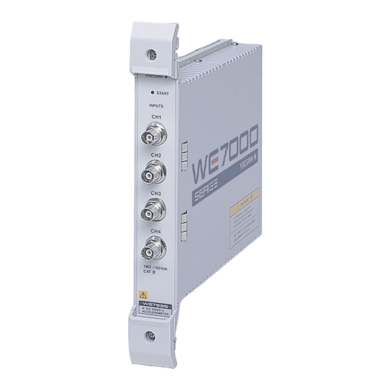
1.7 Names and Function of Sections Front Panel Sampling indicator START Turns ON when the INPUTS input signal is sampled. Input connector BNC terminal used to input the signal to be measured. 60Vpk 4-CH 100kS/s ACCELEROMETER 1-11 IM 707235-01E... -
Page 18: Chapter 2 Hardware Preparation
Chapter 2 Hardware Preparation 2.1 Installing the Module into the Measuring Station Preparing to Install the Module The measuring station comes with each slot covered with a cover plate as shown in the figure below. Verify that the power supply is not connected to the measuring station, and then loosen the module attachment screws (2 locations) and remove the cover plate from the slot where the module is going to be installed. - Page 19 2.1 Installing the Module into the Measuring Station When removing the module Ejection lever Module attachment screw Module attachment screw Note When synchronizing accelerometer modules for measurement (module linking), install the multiple accelerometer modules in adjacent slots. IM 707235-01E...
-
Page 20: Connecting Acceleration Sensors
The acceleration signal (charge signal) that has been converted to a voltage signal by the charge amplifier is input to the WE7235 using a normal coaxial cable. The WE7235 measures the signal in the voltage measurement mode. - Page 21 The WE7235 measures the signals in the acceleration measurement mode and supplies current (bias) to the charge converter. Set the input sensitivity of the WE7235 according to the charge converter gain and the sensitivity of the charge output type acceleration sensor.
-
Page 22: Connecting The Input Cable
2.3 Connecting the Input Cable A BNC cable is used to input the signal to be measured. Connect the BNC cable to the input terminal (BNC terminal indicated as CH1 through CH4) on the front panel of the module. The input signal must conform to the following: Number of inputs: Input format: Non-isolated, unbalanced... -
Page 23: Chapter 3 Troubleshooting And Maintenance
3.1 Troubleshooting • If servicing is necessary, or if the analyzer is not operating correctly after performing the following corrective actions, contact your nearest YOKOGAWA dealer as listed on the back cover of this manual. • To verify that the module is operating correctly, perform the self test as described on the next page. -
Page 24: Acceleration Sensor Connection Test
3.2 Acceleration Sensor Connection Test The test performs diagnosis on shorted and opened conditions of the acceleration sensors including the cables. CAUTION Perform the connection test only when acceleration sensors are connected. A current of approximately 4 mA is supplied to the acceleration sensors during the test. - Page 25 Normal: Input voltage between 2 V and 20 V Open: Input voltage greater than 20 V Short: Input voltage less than 2 V If you remove the On check box under Connection Test, the WE7235 returns to normal measurement. IM 707235-01E...
-
Page 26: Self Test
If a value other than 0 is displayed in the Result display box of the Self Test dialog box, the module is probably malfunctioning. Please contact your nearest YOKOGAWA dealer as listed on the back cover of this manual for repairs. -
Page 27: Maintenance
There are no parts in this module that require periodic replacement. Calibration We recommend that you calibrate the measurement module once a year to assure its measurement accuracy. Please contact your nearest YOKOGAWA dealer to have the module calibrated. IM 707235-01E... -
Page 28: Chapter 4 Specification
Chapter 4 Specification 4.1 Performance Specifications Number of Input Channels Input Format Non-isolated unbalanced input Connector Type Measurement Mode Acceleration measurement and voltage measurement Input Coupling When measuring acceleration: AC only When measuring voltage: DC and AC A/D Resolution Equivalent to 16 bits (including the sign) Input Impedance Approx. - Page 29 4.1 Performance Specifications Acceleration Measurement Applicable acceleration sensor: Built-in amplifier type Sensor supply current: OFF or 4 mA±10% Sensor supply voltage: OFF or approx. 21 VDC Sensitivity setting: Enter the acceleration sensor sensitivity on the operation screen (or using the WE Control API (sold separately, model: 707741)) Measurement range: Measurement range automatically set according to the...
- Page 30 4.1 Performance Specifications Time Base Source Module’s internal clock or the time base signal (CMNCLK) of the measuring station (WE bus), FFT time base (selectable only on the WE Control API (sold separately, model: 707741)) Maximum Sampling Rate 100 kS/s Internal Time Base 10 µs to 10 s (1-µs steps) FFT Time Base (selectable only on the WE Control API (sold separately, model: 707741)
-
Page 31: Default Values (Factory Default Settings)
4.2 Default Values (Factory Default Settings) On (measurement ON/OFF): On (CH1 to CH4) Bias (supply voltage to the acceleration sensor ON/OFF): Off Coupling (input coupling selection): AC Unit (measurement range unit): m/s2 (m/s Range/Gain (measurement range/gain): ×1 Sensitivity (acceleration sensor sensitivity): 0.0 mV/Unit Acquisition Mode: Triggered Sampling Interval: 0.000010 s Memory Partition: 1... -
Page 32: General Specifications
4.3 General Specifications Safety Standards Complies with CSA C22.2 No.1010.1 and EN61010-1, conforms to JIS C1010-1 • Overvoltage Category CAT I and II • Pollution Degree 1 and 2 *1 Overvoltage Categories define transient overvoltage levels, including impulse withstand voltage levels. Overvoltage Category I: Applies to equipment supplied with electricity from a circuit containing an overvoltage control device. -
Page 33: External Dimensions
4.4 External Dimensions Unit: mm WE7235 4-CH, 100 kS/s Accelerometer Module START INPUTS 60Vpk 4-CH 100kS/s ACCELEROMETER If not specified, the tolerance is ±3%. However, in cases of less than 10 mm, the tolerance is ±0.3 mm. IM 707235-01E... -
Page 34: Index
Index Index Input/Output of Time Base Signals ........1-9 Symbols Internal ................1-7 *.csv ................... 1-8 *.wvf ................... 1-8 Low ..................1-7 AAF ..................1-4 AC ..................1-3 Manual Trigger ..............1-7 Acceleration Sensor Connection Test ......3-2, 3-3 Measurement Range ............1-3 Acceleration Sensors ............
Need help?
Do you have a question about the WE7235 and is the answer not in the manual?
Questions and answers