Table of Contents
Advertisement
Quick Links
Service Manual
EN
Electronic Stroke Counter
It is the Customer's responsibility to have all operators and service personnel read and understand this
Contact your local Carlisle Fluid Technologies representative for additional copies of this manual.
READ ALL INSTRUCTIONS BEFORE OPERATING THIS PRODUCT
77-3336 R1.0
Pneumatic Pump
• Model
104261
IMPORTANT! DO NOT DESTROY
manual.
• Model
104263
• Model
104262
www.carlisleft.com
Advertisement
Table of Contents

Subscribe to Our Youtube Channel
Related Manuals for Carlisle BINKS 104263


Summary of Contents for Carlisle BINKS 104263
- Page 1 IMPORTANT! DO NOT DESTROY It is the Customer's responsibility to have all operators and service personnel read and understand this manual. Contact your local Carlisle Fluid Technologies representative for additional copies of this manual. READ ALL INSTRUCTIONS BEFORE OPERATING THIS PRODUCT 77-3336 R1.0...
-
Page 2: Attestation Of Conformity
Providing all conditions of safe use / installation stated within the product manuals have been complied with and also installed in accordance with any applicable local codes of practice. D Smith Director of Sales (EMEA) Signed for and on behalf of Carlisle Fluid Technologies UK Ltd: 5/2/20 Bournemouth,BH11 9LH,UK 77-3336 R1.0... - Page 3 In this part sheet, the words WARNING, CAUTION and NOTE are used to emphasize important safety information as follows: WARNING CAUTION NOTE Hazards or unsafe practices which could result in Hazards or unsafe practices which could result in Important installation, operation or maintenance minor personal injury, product or property severe personal injury, death or substantial property information.
-
Page 4: Specification
Specification 104261 for use with pump: Maple 60, Maple 8/25 104262 for use with pump: Maple 7, Maple 15, Maple 20, Maple 30 104263 for use with pump: DX200 3:1 Sensor output: Namur, two-wire, M12x1 4-pin connector Current consumption (mA) low to high state: 1 maximum to 2.1 minimum Nominal operating voltage (Volts): Switching state indicator: Yellow coloured multihole LED Operating speed (cycles/min): minimum to maximum:... -
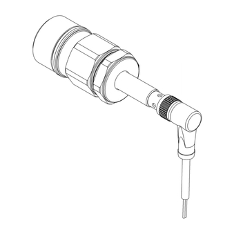
Page 5: Dimensions And Mounting Details
Dimensions and Mounting Details • Model Sensor connections 104261 # 1: Supply 2: Return Connection locating • Model 104262 # These stroke counter units can be fitted at the opposite end of the valve block if preferred. • Model 104263 77-3336 R1.0 5/24 www.carlisleft.com... - Page 6 Stroke Counter Kit Contents 104261 ITEM PART NO. DESCRIPTION REMARKS STROKE COUNTER UNIT WITHOUT 195726 CABLE - MAPLE 60 195714 SENSOR CABLE - 10 METRES 162767 O-RING Note: Spares kit 1 also includes o-ring for item 1. 77-3336 R1.0 6/24 www.carlisleft.com...
- Page 7 Installation 104261 With reference to images and table over page The simplest fitting procedure is to remove end cap and o-ring (10) and replace with stroke counter unit (7), ensuring magnet remains in its correct location. The following procedure outlines the removal of the spool valve assembly and associated parts for cleaning to avoid contamination of the stroke counter.
- Page 8 Installation 104261 GREASE (AGMD-010) TORQUE MAGNET HAZARD Note: External surfaces only around o-rings. Align lug in sensor with notch in plug before fitting. Stroke counter unit Magnet Partial section showing fitting of magnet in stroke counter unit. 77-3336 R1.0 8/24 www.carlisleft.com...
-
Page 9: Components Identification
Components Identification 104261 ITEM PART NO. DESCRIPTION REMARKS 193605 MAIN AIR VALVE ASSEMBLY REPLACE O-RING AND 0115-010425 VALVE BLOCK END CAP REUSE 0115-010424 SPOOL AND SLEEVE ASSEMBLY 0115-010427 BUMPER 0115-010428 MAGNET 0115-010431 SPACER STROKE COUNTER UNIT WITHOUT 195726 CABLE - MAPLE 60 162767 O-RING USED ON ITEM 2... - Page 10 Stroke Counter Kit Contents 104262 ITEM PART NO. DESCRIPTION REMARKS 0115-010049 O-RING STROKE COUNTER UNIT WITHOUT 195727 CABLE - MAPLE 30 195707 VALVE BLOCK END CAP 195708 BUMP STOP 195709 MAGNET - COUNTER 195710 SPACER - COUNTER 195714 SENSOR CABLE - 10 METRES MAGNET HAZARD...
- Page 11 Installation 104262 With reference to images and table over page System check (if desired): Connect cable (9) to the sensor on unit (3) with power off and observing correct orientation. Turn on power then gently press in black plastic pin opposite end to sensor in unit (3) until it comes to a halt.
- Page 12 Installation 104262 GREASE (AGMD-010) TORQUE MAGNET HAZARD ✓ Note: External surfaces only around o-rings. Align lug in sensor with notch in plug before fitting. Valve spool end with solid face must be same end as stroke counter. Bump stop sits with smaller diameter inside end of sleeve, slotted face outwards - both ends.
- Page 13 Components Identification 104262 ITEM PART NO. DESCRIPTION REMARKS 0115-010102 AIR VALVE ASSEMBLY 0115-010015 SPOOL AND SLEEVE ASSEMBLY STROKE COUNTER UNIT WITHOUT 195727 CABLE - MAPLE 30 195707 VALVE BLOCK END CAP 195708 BUMP STOP 195709 MAGNET - COUNTER 195710 SPACER - COUNTER 0115-010049 O-RING 195714...
- Page 14 Stroke Counter Kit Contents 104263 ITEM PART NO. DESCRIPTION REMARKS SPOOL AND TARGET ASSEMBLY - 195725 DX200-3 SENSOR AND HOUSING ASSEMBLY - 195728 DX200-3 SPA-122X O-RING DVX-346 GASKET 195714 SENSOR CABLE - 10 METRES Note: Alternative variant which may be supplied as item 1.
- Page 15 Installation 104263 With reference to images and table over page System check (if desired): Connect cable (10) to the sensor (9) with power off and observing correct orientation. Turn on power then bring the steel target on the end of the spool (3) up against the end face of the black plastic housing containing the sensor (9) to trigger it.
- Page 16 Installation 104263 GREASE (AGMD-010) TORQUE Note: Side with wider slots against gasket. Grease all external faces. Remove air line fitting before extracting spool. Steel target end faces sensor. Chamfered face inside. Grease o-ring mating faces. Align lug in sensor with notch in plug before fitting. 77-3336 R1.0 16/24 www.carlisleft.com...
- Page 17 Components Identification 104263 ITEM PART NO. DESCRIPTION REMARKS DVX-317 VALVE BLOCK DVX-318 SLIDER BLOCK SPOOL AND TARGET ASSEMBLY - 195725 DX200-3 REPLACE O-RING AND DVX-324 END CAP REUSE SPA-122X O-RING USED ON ITEM 4 DVX-343 VALVE PLATE DVX-345 27mm INTERNAL CIRCLIP DVX-346 GASKET FIT NEW GASKET...
-
Page 18: Fault Finding
Fault Finding Symptom Possible Cause Remedy 104261: Check spool and sleeve are central in valve block and spool not jammed. Check parts assembled and mounted in correct order - check against outline dimensions. 104262: Check spool and sleeve are central in valve block and spool not jammed. -
Page 19: Maintenance Schedule
Maintenance schedule Inspection Operation 77-3336 R1.0 19/24 www.carlisleft.com... - Page 20 Accessories PART NO. DESCRIPTION 195730 SENSOR CABLE - 5 METRES 195714 SENSOR CABLE - 10 METRES 195731 SENSOR CABLE - 20 METRES 195732 SENSOR CABLE - 40 METRES AGMD-010 KLUBER ISOFLEX TOPAS NB52 GREASE 77-3336 R1.0 20/24 www.carlisleft.com...
- Page 21 Spares Kits KIT No. PART NO. DESCRIPTION REMARKS 250826 104261 STROKE COUNTER SERVICE KIT 250827 104262 STROKE COUNTER SERVICE KIT 250828 104263 STROKE COUNTER SERVICE KIT STROKE COUNTER UNIT WITHOUT 195726 CABLE - MAPLE 60 STROKE COUNTER UNIT WITHOUT 195727 CABLE - MAPLE 30...
- Page 22 NOTES 77-3336 R1.0 22/24 www.carlisleft.com...
- Page 23 NOTES 77-3336 R1.0 23/24 www.carlisleft.com...
-
Page 24: Warranty Policy
WARRANTY POLICY This product is covered by Carlisle Fluid Technologies’ materials and workmanship limited warranty. The use of any parts or accessories, from a source other than Carlisle Fluid Technologies, will void all warranties. Failure to reasonably follow any maintenance guidance provided, may invalidate any warranty.
Need help?
Do you have a question about the BINKS 104263 and is the answer not in the manual?
Questions and answers