
Related Manuals for KNOVA KN M-2502N


Summary of Contents for KNOVA KN M-2502N
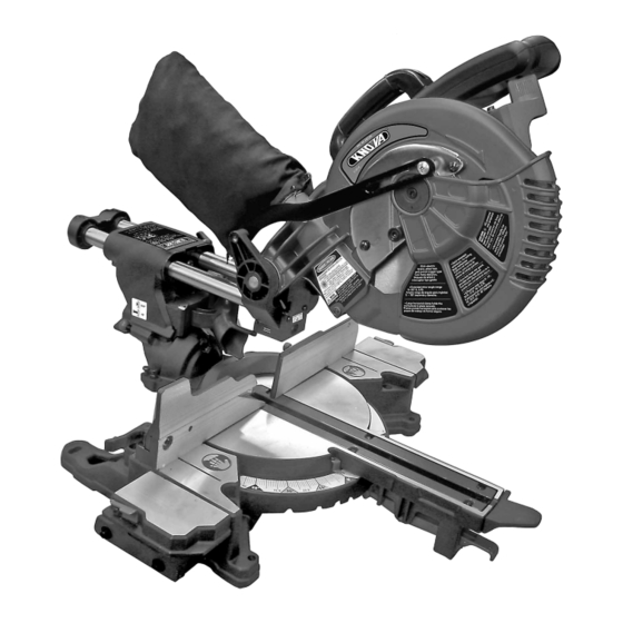
- Page 1 ” Metal and wood slide compound miter saw Sierra angular compuesta deslizable para metal y madera KN M-2502N...
-
Page 2: Table Of Contents
TABLE OF CONTENTS Product specifications ............1 Glossary of terms .............. Warnings ................1 Assembly ................Symbols ................1 Adjustments ..............11 Power tool safety ..............2 Operation ................14 Slide compound miter saw safety ........3 Maintenance ..............21 Electrical requirements and safety ........ -
Page 3: Power Tool Safety
POWER TOOL SAFETY GENERAL SAFETY INSTRUCTIONS BEFORE USING THIS 14. SECURE WORK. Use clamps or a vise to hold work when practical. It is safer than using your POWER TOOL hand and it frees both hands to operate the tool Safety is a combination of common sense, staying aled and knowing how to use your power tool. -
Page 4: Slide Compound Miter Saw Safety
SLIDE COMPOUND MITER SAW SAFETY SPECIFIC SAFETY INSTRUCTIONS FOR THIS 16. ALWAYS keep the blade guards in place and COMPOUND MITER SAW use at all times. 1. DO NOT USE THIN KERF BLADES, they can deflect and 17. NEVER reach around the saw blade. contact guard and can cause possible injury to the operator. -
Page 5: Pre-Assembly
ACCESSORIES Phillips Screwdriver Visit your Knova Hardware Department or see the Knova Power and Hand Tool Catalog to purchase recommended accessories for this power tool. WARNING • To avoid the risk of personal injury, do not modify this power tool or use Slotted Screwdriver accessories not recommended by Knova. -
Page 6: Carton Contents
To avoid electric shock, use only identical replacement parts when 1. Remove the miter saw from the carton. servicing double insulated tools. Call 01-800-70-KNOVA (56682) IMPORTANT: Do not lift miter saw by the trigger switch for replacement parts. -
Page 7: Know Your Slide Compound Miter Saw
KNOW YOUR SLIDE COMPOUND MITER SAW dust Collector Carrying Handle Bevel Detent Pin Bevel Lock Handle Safety Lock Sliding Fence Mounting Holes Miter Handle Vise Base Clamp Left Extension Table Head Hold-Down Latch Laser ON/OFF Slide Carriage Switch Switch Handle Slide Carriage Lock Knob dust Port... -
Page 8: Glossary Of Terms
GLOSSARY OF TERMS AMPERAGE (AMPS) – A measure of the flow of electric POSITIVE STOP LOCKING LEVER – Locks the miter saw at current. Higher ratings generally means the tool is suited for a preset positive stop for the desired miter angle. heavier use. -
Page 9: Assembly
ASSEMBLY CUTTING HEAD (FIG. D) WARNING To avoid injury, do not connect this miter saw to the power source until it is completely assem- WARNING To avoid injury and damage to the saw, bled and adjusted and you have read and understood transport and store the miter saw with the cutting head this instruction Manual. - Page 10 ASSEMBLY INSTALLING THE VISE CLAMP (FIG. F) Removing Blade (Fig. H, I, J, K) NOTE: The vise clamp is used to secure the workpiece during 1. Unplug the saw from the outlet. cutting operations. 2. Allow the miter saw to rise 1.
- Page 11 ASSEMBLY Installing Blade (Fig. H, I, J, K) Mounting instructions: Unplug the miter saw before changing/installing the blade. 1. For stationary use, place the saw in the desired location, directly on a workbench where there is room for handling 1. Install a 10 in. blade, making sure the rotation arrow on the and proper support of the workpiece.
-
Page 12: Adjustments
ADJUSTMENTS ADJUSTMENT INSTRUCTIONS 3. If the blade is not at 45° to the miter table, tilt the cutting arm to the right, loosen the locknut (2) on the bevel angle WARNING To avoid injury from an accidental start, adjustment bolt (3) and use a 10 mm wrench to adjust make sure the switch is in the OFF position and the the stop bolt (3) depth in or out to increase or decrease plug is not connected to the power source outlet. - Page 13 ADJUSTMENTS MITER SCALE INDICATOR (FIG. R) ADJUSTING EXTENSION HEIGHT TO MAIN TABLE (FIG. U) 1. Move the table to the 0° positive stop. 1. Tighten the two lock knobs (1) to lock the extension (2). 2. Loosen the screw (4) that holds the indicator with a 2.
- Page 14 ADJUSTMENTS THE LASER GUIDE (FIG. X) LASER BEAM ADJUSTMENT (FIG. Y, Z, AA, BB) The saw is equipped with a laser guide (1) using a Class IIIa NOTE: laser beam. The laser beam will enable you to preview the • All the adjustments for the operation of the laser guide has saw blade path on the workpiece to be cut before starting the been completed at the factory.
-
Page 15: Operation
OPERATION SAFETY INSTRUCTIONS FOR BASIC SAW OPERATION • Choose the correct 10 in. diameter blade for the material and the type of cutting you plan to do. Do not use thin BEFORE USING THE MITER SAW kerf blades. WARNING To avoid mistakes that could cause •... - Page 16 OPERATION INSPECT YOUR WORKPIECE BODY AND HAND POSITION (FIG. CC) Make sure there are no nails or foreign objects in the part of WARNING Never place hands near the cutting area. the workpiece being cut. Plan your work to avoid small pieces Proper positioning of your body and hands when oper- that may bind, or that are too small to clamp and get a sol- ating the miter saw will make cutting easier and safer.
- Page 17 OPERATION WARNING BEFORE LEAVING THE SAW Fig. DD To avoid injury, • Never leave tool running unattended. Turn power OFF. after completing a cut and Wait for all moving parts to stop and unplug unit from releasing the trigger switch, power source.
- Page 18 OPERATION Fig. HH SLIDE CUTTING WIDE BOARDS UP TO 12 IN. WIDE (FIG. KK) To avoid injury: • Never pull the cutting head assembly and spinning blade toward you during the cut. The blade may try to climb up on the top of the workpiece, causing the cutting assembly and spinning blade to kick back, forcefully.
- Page 19 OPERATION Blade slot CUTTING BOWED MATERIAL (FIG. MM) Fig. OO NOTE: Hold-down clamp is optional. A bowed workpiece must be positioned against the fence and secured with a clamp (1) before cutting as shown. Do not position workpiece incorrectly or try to cut the workpiece without the...
- Page 20 OPERATION Fig. QQ Bevel/Miter Settings Settings for standard crown molding lying flat on compound miter saw table Workpiece Workpiece Inside corner Fig. RR Miter saw table Miter saw table Outside corner Compound cut crown moldings NOTE: The chart below references a compound cut for crown molding ONLY WHEN THE ANGLE BETWEEN THE WALLS EQUALS 90°.
- Page 21 OPERATION CROWN MOLDING CHART 52/38° Crown Molding 45/45° Crown Molding 52/38° Crown Molding 45/45° Crown Molding Angle miter Bevel miter Bevel Between Angle Setting Setting Setting Setting miter Bevel miter Bevel Walls Between Setting Setting Setting Setting Walls 14.66 17.93 16.71 16.04 32.07...
-
Page 22: Maintenance
3. Arbor bolt loose. 3. Retighten. See REMOVING OR INSTALLING THE BLADE section. 4. Brushes cracked, damaged, etc. 4. Replace brushes. 5. Other. 5. Contact Knova Service Centre. motor does 1. Limit switch failure 1. Replace limit switch. not start. 2. Brush worn. -
Page 23: Parts List
Any attempt to repair or replace electrical parts on this Miter Saw may create a HAZARD unless repair is done by a qualified service technician. Repair service is available at your nearest Knova Service Centre. ORDER ONLY BY MODEL NUMBER AND PART NUMBER I.D. - Page 24 PARTS LIST ORDER ONLY BY MODEL NUMBER AND PART NUMBER I.D. No. D e s c r i p t i o n S i z e Qty. I.D. No. D e s c r i p t i o n S i z e Qty.
-
Page 25: Schematic
SCHEMATIC 394Y 2F64 394X 394S 394V 394U 394T 394W 2F7Z 2F9N 358C 38N8 KN M-2502N ” Metal and wood slide compound miter saw 2WUY Sierra angular compuesta deslizable para metal y madera... -
Page 26: Parts List And Diagram (Motor)
PARTS LIST AND DIAGRAM (MOTOR) ORDER ONLY BY MODEL NUMBER AND PART NUMBER I.D. No. D e s c r i p t i o n S i z e Qty. I.D. No. D e s c r i p t i o n S i z e Qty. -
Page 27: Especificaciones Del Producto
INDICE Especificaciones del producto ..........26 Glosario de términos ............32 Advertencia ................ 26 Ensamblaje ................ 33 Símbolos de seguridad ............26 Ajustes ................36 Seguridad en el manejo de herramientas eléctricas ..27 Operación ................39 Seguridad de la Sierra Ingleteadora Compuesta Deslizante ... 28 Mantenimiento .............. -
Page 28: Seguridad En El Manejo De Herramientas Eléctricas
SEGURIDAD EN EL MANEJO DE HERRAMIENTAS ELECTRICAS INSTRUCCIONES GENERALES DE SEGURIDAD ANTES DE 13. USE UNA MÁSCARA ANTIPOLVO PARA UTILIZAR ESTA HERRAMIENTA ELÉCTRICA PROTEGER EL ROSTRO. La operación de la sierra La seguridad es la combinación del sentido común, de manten- produce polvo. -
Page 29: Seguridad De La Sierra Ingleteadora Compuesta Deslizante
SEGURIDAD DE LA SIERRA INGLETEADORA COMPUESTA DESLIZANTE INSTRUCCIONES DE SEGURIDAD ESPECÍFICAS PARA 15. NUNCA use las cuchillas recomendadas para operar a ESTA SIERRA INGLETEADORA COMPUESTA menos de 2.400 RPM. 16. SIEMPRE mantenga los protectores de la cuchilla en su 1. NO USE CUCHILLAS DE CORTE FINO, pueden lugar y utilícelos todas las veces. -
Page 30: Pre-Ensamblado
REQUISITOS ELECTRICOS Y SEGURIDAD Para reducir el riesgo de descargas eléctricas, esta sierra puede ocasionar una caída en el voltaje de la línea y, en con- tiene un enchufe polarizado (una patilla es más gruesa que la secuencia, una pérdida de potencia y el recalentamiento de la otra). -
Page 31: Contenido De La Caja
PRE-ENSAMBLADO SUMINISTRADAS NO SUMINISTRADAS ACCESORIOS Comuníquese con el soporte técnico o vaya a la tienda de su área para obtener los accesorios de su herramienta eléctrica. Llave hexagonal Llave para la hoja de 4 mm y 10 mm. ADVERTENCIA • Para evitar el riesgo de heridas personales, no modifique esta herramienta eléctrica ni utilice accesorios que no estén recomendados por el servicio al cliente. -
Page 32: Conozca Su Sierra Ingleteadora Compuesta Deslizable
CONOZCA SU SIERRA INGLETEADORA COMPUESTA DESLIZANTE Recolector de polvo Manija transportadora Clavijas de detención del bisel Manija de traba del bisel Bloqueo de seguridad Guía deslizante Orificios de montaje Mango para ingletes Mesa de Base Mordaza extensión de apriete izquierda Pestillo de sujeción Interruptor de encendido/apagado... -
Page 33: Glosario De Términos
GLOSARIO DE TERMINOS AMPERAJE (AMPS): Una medida del flujo o corriente eléc- PALANCA DE FIJACIóN DEL TOPE POSITIVO: Traba la si- trica. Si el amperaje es algo, generalmente significa que la erra ingleteadora en una posición predeterminada, para lograr herramienta es adecuada para uso pesado. el ángulo de inglete deseado. -
Page 34: Ensamblaje
ENSAMBLAJE CABEZAL DE CORTE (FIG. D) ADVERTENCIA Para evitar heridas, no conecte esta sierra ingleteadora a la fuente de alimentación hasta ADVERTENCIA Para evitar heridas o daños en la que esté completamente ensamblada y ajustada, y sierra ingleteadora, transpórtela o guárdela con el hasta haber leído y entendido este Manual de operador. - Page 35 ENSAMBLAJE 4. Levante el protector inferior de la hoja Fig. F (1) a la posición superior. (Fig. I) 5. Coloque la llave hexagonal de 6 mm sobre el perno del eje (4). Fig. H 6. Colocar la llave de la hoja RETIRAR E INSTALAR EL INSERTO DE LA MESA (FIG.
- Page 36 ENSAMBLAJE 1. Instale una cuchilla de 10” (254 mm.), asegurándose de Instrucciones de montaje: que la flecha de rotación de la cuchilla concuerde con la 1. Para uso fijo, coloque la sierra en la ubicación deseada, flecha de rotación en el sentido de las agujas del reloj que directamente sobre un banco de trabajo en el que haya se encuentra en el protector superior.
-
Page 37: Ajustes
AJUSTES INSTRUCCIONES PARA LOS AJUSTES Ajuste de bisel a 45¡ (FIG. Q) 1. Loosen the 1. Afloje la manija de traba del bisel (1) ADVERTENCIA Para evitar las heridas causadas por e incline el cabezal de corte completamente hacia la el encendido accidental, asegúrese de que el interrup- izquierda. - Page 38 AJUSTES INDICADOR DE LA ESCALA DE INGLETES (FIG. R) 2. Ajuste la perilla de tope (1) para que toque la placa de tope (2). 1. Mueva la mesa hacia el tope positivo 0°. 3. Vuelva a comprobar la profundidad de la cuchilla moviendo 2.
- Page 39 AJUSTES EL CONDUCTO DE ESCAPE Fig. Y DE POLVO (FIG. W) 1. Para evitar que se desparrame el polvo de metal, gire la placa de la cubierta (1) para cubrir el conducto de escape de polvo (2) al cortar la pieza de metal. Fig.
-
Page 40: Operación
AJUSTES C. Alineación del rayo láser (Fig. Y, Z, AA, BB) (4) en sentido contrario al reloj, cuando las guías del rayo láser den derecha a izquierda, gire el montaje del 1. Retire la tapa de láser (2) aflojando los dos tornillos (3). láser (4) en sentido del reloj. - Page 41 OPERACION • Asegúrese de que la cuchilla esté afilada, de que no esté • Utilice calzado antideslizante. dañada y de que esté alineada correctamente. Con la sierra • Si tiene el cabello largo, áteselo. desenchufada, empuje el brazo de corte completamente hacia abajo.
- Page 42 OPERACION • Cuando corte piezas de trabajo irregulares, planifique Terminar un corte: el trabajo, para que no se atasquen en la cuchilla y le • Mantenga el brazo de corte en la posición hacia abajo. ocasionen alguna herida. Una moldura, por ejemplo, debe estar en posición horizontal o debe sujetarse con un •...
- Page 43 OPERACION SISTEMA DEL SOPORTE DESLIZANTE (FIG. EE) CORTE DE INGLETES (FIG. GG) ADVERTENCIA ADVERTENCIA Sólo use la sierra ingletadora para Para reducir el riesgo de heridas, hacer un corte transversal en los metales. Nunca lo devuelva el carro totalmente a la posición trasera use para hacer el corte de ingletes, corte en bisel o después de realizar cada corte transversal.
- Page 44 OPERACION TOPE DE BISEL A 33.9° PARA MOLDURAS TIPO CORONA • Deje que la cuchilla alcance el máximo de velocidad antes (FIG. II) de realizar un corte. Esto ayudará a reducir el riesgo de que la pieza de trabajo salga despedida 1.
- Page 45 OPERACION Fig. OO CORTE DE MATERIALES Ranura de CURVADOS (FIG. MM) la cuchilla NOTA: La abrazadera de sujeción es opcional. Una pieza de trabajo curvada debe colocarse contra la guía de la sierra y asegurarse con una abrazadera (1) antes de realizar el corte, como se muestra abajo.
- Page 46 OPERACION Para cortar con precisión una moldura tipo corona para una Configuración de Inglete/Bisel esquina interna o externa de 90¡ , coloque la moldura con la Configuración para moldura estándar tipo corona colocada superficie amplia trasera horizontalmente sobre la mesa de de forma horizontal sobre la mesa de la sierra ingleteadora la sierra.
- Page 47 OPERACION TABLA DE MOLDURA DE CORONACION Moldura de corona de 52/38° Moldura de corona de 45/45° Moldura de corona de 52/38° Moldura de corona de 45/45° Angulo Configuración Configuración Configuración Configuración formado por Angulo de bisel de inglete de bisel de inglete Configuración Configuración...
-
Page 48: Mantenimiento
3. Vuelva a ajustarlo. Vea la sección RETIRAR 3. El perno del eje está flojo. O INSTALAR LA CUCHILLA. 4. Las escobillas están partidas, dañadas, etc. 4. Reemplace las escobillas. 5. Contacte al Centro de servicio Knova. 5. Otro. -
Page 49: Lista De Piezas
PELIGROSO, a menos que la reparación sea efectuada por un técnico de servicio calificado. NÚMERO DE MODELO El servicio de reparaciones está disponible en el centro de servicio Knova más cercano. Y NÚMERO DE PARTE No. de ID D e s c r i p c i ó... - Page 50 LISTA DE PIEZAS SOLICITAR SóLO POR NÚMERO DE MODELO Y NÚMERO DE PARTE No. de ID D e s c r i p c i ó n T a m a ñ o Cant. No. de ID D e s c r i p c i ó n T a m a ñ...
-
Page 51: Vista Esquematica
VISTA ESQUEMATICA 394Y 2F64 394X 394S 394V 394U 394T 394W 2F7Z 2F9N 358C 38N8 KN M-2502N ” Metal and wood slide compound miter saw 2WUY Sierra angular compuesta deslizable para metal y madera... -
Page 52: Lista De Piezas Y Diagrama (Motor)
LISTA DE PIEZAS Y DIAGRAMA ( MOTOR) SOLICITAR SóLO POR NÚMERO DE MODELO Y NÚMERO DE PARTE No. de ID D e s c r i p c i ó n T a m a ñ o Cant. No. de ID D e s c r i p c i ó... - Page 53 www.knova.com.mx...
Need help?
Do you have a question about the KN M-2502N and is the answer not in the manual?
Questions and answers