
Related Manuals for KNOVA KN M-3057R


Summary of Contents for KNOVA KN M-3057R
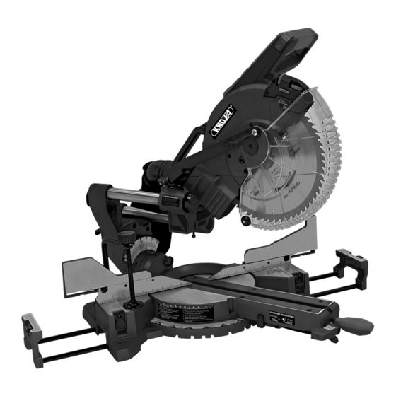
- Page 1 ” Compact sliding compound miter saw Sierra angular compuesta deslizable compacta KN M-3057R...
-
Page 2: Table Of Contents
TABLE OF CONTENTS Table of contents .............. Glossary of terms .............. Product specifications KN M-3057R ......... Assembly ................Warnings ................Setting the tool ..............11 Symbols ................1 Connecting to the power supply ........15 Power tool safety .............. Mounting the tool .............. 15 Compact sliding compound miter saw safety .... -
Page 3: Warnings
POWER TOOL SAFETY GENERAL SAFETY INSTRUCTIONS BEFORE USING 14. SECURE WORK. Use clamps or a vise to hold work when practical. It is safer than using your THIS POWER TOOL hand and it frees both hands to operate the tool. Safety is a combination of common sense, staying alert and knowing how to use your power tool. -
Page 4: Compact Sliding Compound Miter Saw Safety
COMPACT SLIDING COMPOUND MITER SAW SAFETY SPECIFIC SAFETY INSTRUCTIONS FOR THIS 22. PROVIDE adequate support to the sides of the saw table COMPOUND MITER SAW for long work pieces. 23. NEVER use the miter saw in an area with flammable DO NOT USE THIN KERF BLADES they can deflect and liquids or gases. -
Page 5: Electrical Requirements And Safety
ELECTRICAL REQUIREMENTS AND SAFETY POWER SUPPLY AND MOTOR SPECIFICATIONS 4. FUSES may “blow” or circuit breakers may trip frequently if: The AC motor used in this saw is a universal, nonreversible a. MOTOR is overloaded – overloading can occur if you feed too rapidly or make too many start/stops in a short time. -
Page 6: Accessories And Attachments
ACCESSORIES the HSS blades are generally less expensive than carbide Visit your Knova store or see the Knova power and hand tool tipped, TCT blades will stay sharper longer than HSS. As a catalog to purchase recommended accessories for this power general rule the more teeth per inch (TPI) the smoother the tool. -
Page 7: Carton Contents
IMPORTANT: Always use the designated carrying handle and Call 01-800-70-KNOVA (56682) for replacement parts. hand-hold on the side of the saw base for transportation. Miter saw Blade wrench... -
Page 8: Know Your Compact Sliding Compound Miter Saw
KNOW YOUR COMPACT SLIDING COMPOUND MITER SAW Switch handle Laser vertical Carrying adjustment knob handle Laser horizontal adjustment knob Slide carriage lock knob Lower blade guard Hold-down clamp Base Table insert Slide fence Miter handle Left extension wing Miter Fig. 1 detent override Stop plate... -
Page 9: Glossary Of Terms
GLOSSARY OF TERMS AMPERAGE (AMPS) – A measure of the flow of electric POSITIVE STOP LOCKING LEVER – Locks the miter saw current. Higher ratings generally means the tool is suited at a preset positive stop for the desired miter angle. for heavier use. -
Page 10: Assembly
ASSEMBLY INSTALLING THE MITER HANDLE (FIG. 3) WARNING For your own safety, never connect the plug to power source outlet until all assembly steps 1. Insert the miter handle (5) into the hole in front of the miter are completed and you have read and understood the saw and align the hole (6) on the miter handle (5) with the safety and operational instructions. - Page 11 ASSEMBLY NOTE: There are no screws to secure clamp. The clamp will secure itself to the base when turning the knob (3) to clamp the workpiece. Do not use your other hand to hold the clamp when tightening. Fig. 5 Fig.
-
Page 12: Setting The Tool
SETTING THE TOOL NOTE: This tool is accurately adjusted before shipping from 45° Right Bevel Positive Stop Adjustment (Fig. 11, 12, 13) the factory. Check the following accuracy and readjust them 1. Loosen the bevel locking handle (1) and set cutting arm at if necessary in order to obtain the best results in operation. - Page 13 SETTING THE TOOL Fig. 14 angle settings: 0°, 15°, 22.5°, 31.6°, and 45°. These positive stops position the blade at the desired angle quickly and accurately. Follow the process below for the quickest and most accurate adjustments. Adjusting miter angles: 1.
- Page 14 SETTING THE TOOL ADJUSTING CUTTING DEPTH (FIG. 19, 20) 3. Recheck the blade depth by moving the cutting head front to back through the full motion of a typical cut along the The maximum depth travel of the cutting head was set at the control arm.
- Page 15 SETTING THE TOOL THE LASER LINE TURNING LASER GUIDE ON (FIG. 24) 1. To turn laser on, press on/off rocker switch (1) to “I” WARNING For your own safety, never connect the position. plug to power source outlet until all the adjustment steps are complete and you have read and 2.
-
Page 16: Connecting To The Power Supply
SETTING THE TOOL Counterclockwise Clockwise 5. Slide the cutting head forward enough so that the laser line Fig. 27 is visible on the front of the board. 6. Looking at the front of the board, if the laser line is not parallel to the “pattern line”... -
Page 17: Operating The Tool
MOUNTING THE TOOL has eight mounting holes, four 1/4 in. holes and four 2. For portable use, place the saw on a 3/4 in. thick piece 3/8 in. holes. Select the proper mounting holes based on of plywood. Bolt the base of the miter saw securely to the the size of bolts used. - Page 18 OPERATING THE TOOL MITER DETENT OVERRIDE (FIG. 36) The miter detent override allows for the table to be micro adjusted, disengaging the positive detent stops feature. When a required miter angle is close to a positive detent stop, this override prevents the wedge on the miter arm from slipping into that detent slot on the base.
- Page 19 OPERATING THE TOOL 3. Release the positive stop locking lever (2) and set the 4. Turn the laser guide on and position the workpiece on the miter at the desired angle making sure the lever snaps into table for pre-alignment of cutting. place.
- Page 20 OPERATING THE TOOL NOTE: Horizontal Position Vertical Position SETTINGS (Back of molding is (Back of molding is • These special stops can not be used with 45° crown flat on the table) against the fence) molding. Bevel Angle 0° 45° •...
-
Page 21: Changing Blades
CHANGING BLADES Removing the blade (Fig. 44, 45, 46) 5. Place the blade wrench on the arbor bolt (4). 6. Press the arbor lock WARNING Do not use a blade larger than 12 in. button (5), holding it in diameter. To avoid injury from an accidental start, in firmly while turning make sure the switch is in the OFF position and the Fig. -
Page 22: Maintenance
MAINTENANCE Replace the other side in the same manner. To reassemble, WARNING For your own safety, turn the switch off reverse the procedure. The ears on the metal end of the and remove the plug from the power source outlet assembly go in the same hole in which the carbon part fits. -
Page 23: Parts List
PARTS LIST ORDER ONLY BY MODEL NUMBER AND PART NUMBER I.D. No. D e s c r i p t i o n S i z e Qty. I.D. No. D e s c r i p t i o n S i z e Qty. - Page 24 PARTS LIST ORDER ONLY BY MODEL NUMBER AND PART NUMBER I.D. No. D e s c r i p t i o n S i z e Qty. I.D. No. D e s c r i p t i o n S i z e Qty.
-
Page 25: Diagram Parts
DIAGRAM PARTS KN M-3057R ” Compact sliding compound miter saw Sierra angular compuesta deslizable compacta... -
Page 26: Parts List And Motor Diagram
42S2 CUTTER SHAFT 3FJD FRONT HOUSINT 42S3 BALL BEARING 3FJE CLEVIS PIN 3FJF LOCK KNOB 3FJM MOTOR COVER 3FJR GEAR BOX 3GGC COMPRESSION SPRING 3GGU OIL CAP KN M-3057R ” Compact sliding compound miter saw Sierra angular compuesta deslizable compacta... -
Page 27: Indice
INDICE Indice ................. 26 Glosario de términos ............33 Especificaciones del producto KN M-3057R ..... 26 Ensamble ................34 Advertencia ................ 26 Ajuste de la herramienta ........... 36 Símbolos de seguridad ............26 Conexión a la red eléctrica ..........40 Seguridad en el manejo de herramientas eléctricas .. -
Page 28: Seguridad En El Manejo De Herramientas Eléctricas
SEGURIDAD EN EL MANEJO DE HERRAMIENTAS ELECTRICAS INSTRUCCIONES GENERALES DE SEGURIDAD ANTES DE 13. USE UNA MÁSCARA ANTIPOLVO PARA UTILIZAR ESTA HERRAMIENTA ELÉCTRICA PROTEGER EL ROSTRO. La operación de la sierra produce polvo. La seguridad es la combinación del sentido común, de mantenerse alerta y de saber cómo utilizar su herramienta eléctrica. -
Page 29: Seguridad Para La Sierra Angular Compuesta Deslizable Compacta
SEGURIDAD PARA LA SIERRA ANGULAR COMPUESTA DESLIZABLE COMPACTA ESPECIFICACIONES DEL MOTOR Y DEL SUMINISTRO 21. NUNCA corte piezas pequeñas. La pieza de trabajo que DE ENERGÍA está cortando será muy pequeña si, al sujetarla, sus manos o sus dedos quedan a menos de 22 cm de la NO UTILICE DISCOS DELGADOS PARA CORTAR, ya que hoja de la sierra. -
Page 30: Requisitos Eléctricos Y Seguridad
REQUISITOS ELECTRICOS Y SEGURIDAD 3. Si la herramienta se atasca mientras está cortando ESPECIFICACIONES DEL MOTOR Y LA FUENTE DE madera, suelte el interruptor del gatillo, desenchufe la ALIMENTACIÓN ELÉCTRICA herramienta y desenganche la cuchilla de la madera. El motor CA usado en esta sierra es de tipo universal, no Después de esto, puede volver a encender la sierra para reversible. -
Page 31: Accesorios Y Acoplamientos
ACCESORIOS Aunque las hojas HSS son más baratos que las carburo Visite las tiendas Knova o véase el Catálogo de Herramientas calzado (TCT), la agudeza de las hojas TCT es más larga que Mecánicas y Manuales Knova para comprar los accesorios HSS. -
Page 32: Herramientas Necesarias Para El Montaje
LLAME AL IMPORTANTE: Utilice SIEMPRE los soportes para el 01-800-70-KNOVA (56682) para piezas de repuesto. transporte y agarre manual sobre el lateral del base de la sierra para mover la sierra. -
Page 33: Conozca Su Sierra Angular Compuesta Deslizable Campacta
CONOZCA SU SIERRA ANGULAR COMPUESTA DESLIZABLE COMPACTA Mango de interruptor Perilla para ajuste Manija de vertical de laser transporte Perilla para ajuste horizontal de laser Perilla de bloqueo del soporte deslizante Cubierta de la hoja inferior Prensa de sujeción Base Guía Inserto de la mesa deslizante... -
Page 34: Glosario De Términos
GLOSARIO DE TERMINOS AMPERAJE (A) – Es la medición del flujo de corriente TRABA DE RESORTE DE LA MESA DE INGLETES – Traba eléctrica. Las calificaciones más altas generalmente indican la sierra para cortar ingletes en una posición predeterminada, que la herramienta es apropiada para un uso más pesado. para lograr el ángulo de inglete deseado. -
Page 35: Ensamble
ENSAMBLE INSTALACIÓN DE LA MANIJA DE BLOQUEO PARA ADVERTENCIA Para su propia seguridad, nunca BISELADO (FIG. 3) conecte la clavija en el tomacorriente hasta que todos los pasos de ensamble hayan sido realizados 1. Inserte la manija de bloqueo para biselado (1) en el eje (2) y usted haya leído y comprendido todas las a un ángulo aproximado de unos 30°... - Page 36 ENSAMBLE INSTALACIÓN EL ENSAMBLE DE DE LA ABRAZADERA DE FIJACIÓN (FIG. 5, 6) Fig. 8 Coloque el ensamble de la abrazadera de fijación (1) en uno de los agujeros de montaje (2) ubicados detrás de la guía. NOTA: No hay tornillos para fijar la abrazadera.
-
Page 37: Ajuste De La Herramienta
AJUSTE DE LA HERRAMIENTA NOTA: Esta herramienta se ajusta con precisión antes de Ajuste del indicador del bisel de 90° (Fig. 12) salir de fábrica. Compruebe la precisión de los siguientes 1. Cuando la hoja esté exactamente en 90° (0°) con respecto ajustes y, en caso necesario, modifíquelos para obtener los a la mesa, afloje el tornillo de puntero del bisel (4) con un mejores resultados. - Page 38 AJUSTE DE LA HERRAMIENTA 3. Incline el brazo de corte al tope positivo derecha de 33,9° ESCALA DE INGLETES (FIG. 17) empujándola el pasador de retén para biselado de 33,9° (2). La escala de la sierra deslizante de para cortar ángulos con (Fig.
- Page 39 AJUSTE DE LA HERRAMIENTA AJUSTE DE LA PROFUNDIDAD DE CORTE (FIG. 19, 20) AJUSTES DE LA PALANCA DE BLOQUEO DE LA LEVA RÁPIDA (FIG. 21) El recorrido de máxima profundidad del cabezal de corte se configuró en fábrica. 1. Aprete abajo la palanca de bloqueo de la leva rápida (1) para cerrar la mesa de inglete en su lugar.
- Page 40 AJUSTE DE LA HERRAMIENTA LA LÍNEA DE LÁSER PARA ENCENDER LA GUÍA LÁSER (FIG. 24) 1. Para encender el láser, presione y coloque el interruptor ADVERTENCIA Para su propia seguridad, nunca oscilante de encendido/apagado (1) en la posición “I”. conecte la clavija en el tomacorriente hasta que todos los pasos de ajuste hayan sido realizados 2.
-
Page 41: Conexión A La Red Eléctrica
AJUSTE DE LA HERRAMIENTA En dirección En dirección de 5. Deslice la cabeza de corte bastante adelante para que la contraria a las las manecillas línea de laser sea visible delante de la tabla. manecillas del reloj del reloj 6. Mirando la tabla desde el frente, si el rayo láser no está Fig. -
Page 42: Funcionamiento De La Máquina
MONTAJE DE LA HERRAMIENTA • No lleve la ingleteadora por el cable de alimentación ni por el mango del interruptor. El llevar la máquina 1. Base de la sierra por el cable de alimentación podría provocar daños al ingletadora aislamiento o a las conexiones del cable, lo que podría 2. - Page 43 FUNCIONAMIENTO DE LA MAQUINA • La sierra ingletadora está FUNCIONAMIENTO DE LA LEVA DE SUJECION RAPIDA equipada con un freno DE LA MESA (FIG. 35) eléctrico de la Si los ángulos requeridos NO se corresponden con una de las hoja. Cuando nueve posiciones predeterminadas mencionadas arriba, la se suelta el mesa de ingletes puede trabarse en cualquier ángulo que esté...
- Page 44 FUNCIONAMIENTO DE LA MAQUINA CORTE DE BISEL (FIG. 38, 39) ADVERTENCIA Para evitar lesiones resultantes de materiales que salen despedidos, siempre desenchufe ADVERTENCIA La guía deslizante deberá la sierra para prevenir arranques accidentales y extenderse hacia la izquierda o derecha cuando se quite los trozos de material pequeños de la cavidad efectúen los cortes biselados.
- Page 45 FUNCIONAMIENTO DE LA MAQUINA CORTE COMPUESTO (FIG. 40) CORTE DE MOLDEADO DE CORONA (FIG. 42) Un corte compuesto es la combinación simultánea de un corte 1. Con esta sierra inglete, el moldeado de la corona de inglete y un corte de bisel. únicamente puede cortarse de manera plana sobre la mesa.
-
Page 46: Sustitución De La Hoja
FUNCIONAMIENTO DE LA MAQUINA 1. Destrabe la perilla de bloqueo del soporte deslizante (1) y permita que el conjunto del cabezal de corte se mueva Fig. 43 libremente. 2. Configure el ángulo de bisel o de inglete deseado y trábelo en posición. -
Page 47: Mantenimiento
SUSTITUCION DE LA HOJA 6. Presione el botón de bloqueo de la pérgola (5),sosteniéndo Fig. 46 firmemente mientras gira la hoja en dirección contrario de las manecillas del reloj. Siga presionando mientras aprieta el perno del husillo con firmeza. No quitar ADVERTENCIA •... -
Page 48: Lista De Piezas
LISTA DE PIEZAS PEDIDO SOLO POR NÚMERO DE MODELO Y NÚMERO DE PIEZA No. de ID D e s c r i p c i ó n T a m a ñ o Cant. No. de ID D e s c r i p c i ó n T a m a ñ... - Page 49 LISTA DE PIEZAS PEDIDO SOLO POR NÚMERO DE MODELO Y NÚMERO DE PIEZA No. de ID D e s c r i p c i ó n T a m a ñ o Cant. No. de ID D e s c r i p c i ó n T a m a ñ...
-
Page 50: Diagrama De Partes
DIAGRAMA DE PARTES KN M-3057R ” Compact sliding compound miter saw Sierra angular compuesta deslizable compacta... -
Page 51: Lista De Piezas Y Diagrama Del Motor
3FJD CARCAZA FRONTAL 42S3 BALERO 3FJE PERNO DE INCLINACIÓN 3FJF PERILLA ASEGURADORA 3FJM CUBIERTA DE MOTOR 3FJR CAJA DE ENGRANES 3GGC RESORTE DE COMPRESIÓN 3GGU TAPA DE ACEITE KN M-3057R ” Compact sliding compound miter saw Sierra angular compuesta deslizable compacta... - Page 52 www.knova.com.mx...
Need help?
Do you have a question about the KN M-3057R and is the answer not in the manual?
Questions and answers