
Related Manuals for KNOVA KN M-2508RC


Summary of Contents for KNOVA KN M-2508RC
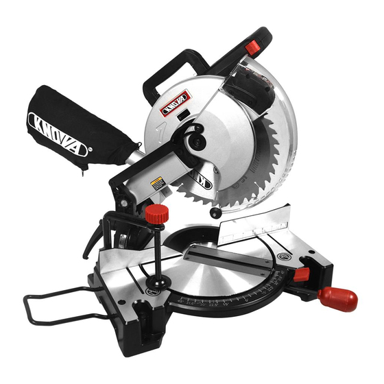
- Page 1 ” Compound miter saw with laser guide Sierra angular compuesta con guía láser KN M-2508RC...
-
Page 2: Table Of Contents
TABLE OF CONTENTS Table of contents ..............1 Glossary of terms .............. Product specifications KN M-2508RC ........ 1 Assembly ................Warnings ................1 Adjustments ..............11 Symbols ................1 Operation ................14 Power tool safety ..............2 Crown molding chart ............19 Compound miter saw safety .......... -
Page 3: Power Tool Safety
POWER TOOL SAFETY GENERAL SAFETY INSTRUCTIONS BEFORE 14. SECURE WORK. Use clamps or a vise to hold work when practical. It is safer than using your hand USING THIS POWER TOOL and it frees both hands to operate the tool. Safety is a combination of common sense, staying alert and knowing how to use your power tool. -
Page 4: Compound Miter Saw Safety
COMPOUND MITER SAW SAFETY SPECIFIC SAFETY INSTRUCTIONS FOR THIS 16. ALWAYS keep the blade guards in place and COMPOUND MITER SAW use at all times. 17. NEVER reach around the saw blade. 1. DO NOT USE THIN KERF BLADES they can deflect and contact guard and can cause possible injury to the operator. -
Page 5: Accessories And Attachments
ACCESSORIES less expensive than carbide tipped, TCT blades will stay sharper Visit your Knova Hardware Department or see the Knova Power and longer than HSS. As a general rule the more teeth per inch (TPI) the Hand Tool Catalog to purchase recommended accessories for this smoother the cut. -
Page 6: Tools Needed For Assembly
1. Remove the miter saw from the carton. electric shock, use only identical replacement parts when IMPORTANT: Do not lift miter saw by the trigger switch servicing double insulated tools. Call 01-800-70-KNOVA handle. It may cause misalignment. Lift machine by the (56682) for replacement parts. -
Page 7: Know Your Compound Miter Saw
KNOW YOUR COMPOUND MITER SAW Safety Lock-Off Button Carrying Handle Cover Plate Upper Blade Guard Dust Bag Lower Blade Guard Fence Hold-down Clamp Bevel Lock Handle Bevel Scale Positive Stop Locking Lever Miter Handle Table Insert Laser On/Off Switch Battery Cover Laser Guide Switch Handle Arbor Lock Button... -
Page 8: Glossary Of Terms
GLOSSARY OF TERMS COMPOUND MITER SAW TERMS WARNING LABELS – Read and understand for your own AMPERAGE (AMPS) – A measure of the flow of electric cur- safety. Make sure all labels are present on machine and legible. rent. Higher ratings generally means the tool is suited for heavier use. - Page 9 ASSEMBLY 2. Pull the hold-down latch (2) out of the short slot (3) and turn 90º to insert into the long slot (4). IMPORTANT: To avoid damage, never carry the miter saw by the switch handle, the cutting arm or the miter handle. ALWAYS use the designated carrying handle (5).
- Page 10 ASSEMBLY INSERTING AND REPLACING THE LASER BATTERIES 7. Locate the arbor lock button (5) below the trigger switch (FIG. F) handle. (Fig. H) 8. Press the arbor lock button (5), holding it in firmly while WARNING Failure to unplug your tool could result in turning the blade wrench clockwise.
- Page 11 ASSEMBLY 2. Place the blade wrench on the arbor bolt. NOTE: The hold-down latch is for carrying or storing the tool. It is not to be used for holding the saw while cutting. Lower 3. Press the arbor lock button (5), holding it in firmly while blade and press in hold-down latch to secure saw for turning the blade counterclockwise.
-
Page 12: Adjustments
ASSEMBLY MITER SCALE (FIG. N) Fig. L The miter scale assists the user in setting the desired miter angles from 45° left to 45° right. The miter saw table has nine of the most common angle setttings with positive 3/4 inch stops at 0°, 15°, 22.5°, 31.6°, and 45°. - Page 13 ADJUSTMENTS 90° Bevel Indicator (Fig. Q) 1. When the blade is exactly 90° to the table, loosen the bevel indicator screw (5) using a #2 Phillips screwdriver. 2. Adjust bevel indicator (6) to the “0” mark (7) on the bevel scale and retighten the screw.
- Page 14 ADJUSTMENTS ALIGNING THE LASER GUIDE The laser line must always be correctly aligned with the blade Laser to ensure straight, even cutting. Your tool is equipped with Aperture the Laser guide cutting guide using Class IIIa laser line. The Label laser line will enable you to preview the saw blade path on the stock to be cut before starting the miter saw.
-
Page 15: Operation
ADJUSTMENTS 2. Slightly turn adjustment screw (2) to adjust the horizontal Fig. U angle of laser line on the top of the board. If the laser line is out of parallel from left to right, turn the adjustment screw (2) clockwise; If the laser line is out of parallel from right to left, turn the adjustment screw (2) counterclockwise until the laser line is parallel with the horizontal pattern line. - Page 16 OPERATION • Check the dust bag before you work. Empty the bag if it is • Noise levels vary widely. To avoid possible hearing more than half-full. damage, wear ear plugs when using any miter saw. • For dusty operations, wear a dust mask along with safety RECOMMENDED ACCESSORIES goggles.
- Page 17 OPERATION WHEN SAW IS RUNNING BASIC SAW OPERATIONS WARNING WARNING Do not allow familiarity from frequent use For your convenience, your saw has of your miter saw to result in a careless mistake. blade brake. The brake is not a safety device. Never A careless fraction of a second is enough to cause a rely on it to replace the proper use of the guard on your severe injury.
- Page 18 OPERATION 4. When the table is in the desired position as shown on the COMPOUND CUT (FIG. BB) miter scale (3), release the positive stop locking lever A compound cut is the combination of a miter and a bevel cut handle and tighten the miter handle.
- Page 19 OPERATION CUTTING BASE MOLDING (FIG. DD) Most crown molding has a top rear angle (the section that fits flat against the ceiling) of 52° and a bottom rear angle (the Base moldings and many other moldings can be cut on a com- section that fits flat against the wall) of 38°.
-
Page 20: Crown Molding Chart
CROWN MOLDING CHART Compound miter saw Miter and bevel angle settings Wall to crewn molding angle... -
Page 21: Maintenance
MAINTENANCE MAINTENANCE SAWDUST Periodically, sawdust will accumulate under the work table DANGER To avoid injury, never put lubricants on the and base. This could cause difficulty in the movement of the blade while it is spinning. worktable when setting up a miter cut. Frequently blow out or vacuum up the sawdust. -
Page 22: Troubleshooting Guide
3. Retighten. See REMOVING OR INSTALLING THE BLADE section. 4. Brushes cracked, damaged, etc. 4. Replace brushes. 5. Other. 5. Contact Knova Service Centre. 1. Replace limit switch. Motor does 1. Limit switch failure. not start. 2. Replace brushes. See MAINTENANCE section. -
Page 23: Parts List
Any attempt to repair or replace electrical parts on this Miter Saw may create a HAZARD un- less repair is done by a qualified service technician. Repair service is available at your nearest Knova Service Centre. I.D. No. -
Page 24: Exploded View
EXPLODED VIEW (254 mm) -
Page 25: Parts List And Exploded View Motor
X3QK CARBON BRUSH ASS’Y X8BC TRADEMARK LABEL X3QL FLOW GUIDE X8BD LASER TRADEMARK LABEL X3QM CR. RE. PAN HD. TAPPING SCREW M5 x 65 X8BE MOTOR LABEL KN M-2508RC ” Compound miter saw with laser guide Sierra angular compuesta con guía láser... -
Page 26: Indice
INDICE Indice ................. 25 Glosario de términos ............31 Especificaciones del producto KN M-2508RC ....25 Montaje ................31 Advertencia ................ 25 Ajustes ................35 Símbolos ................25 Funcionamiento ..............38 Seguridad en el manejo de herramientas eléctricas ..26 Cuadro para molduras de corona ........ -
Page 27: Seguridad En El Manejo De Herramientas Eléctricas
SEGURIDAD EN EL MANEJO DE HERRAMIENTAS ELECTRICAS INSTRUCCIONES GENERALES DE SEGURIDAD ANTES DE 13. UTILICE UNA MASCARA FACIAL O UNA UTILIZAR ESTA HERRAMIENTA ELECTRICA MASCARILLA CONTRA EL POLVO. El trabajo La seguridad es una combinación de sentido común, precaución y realizado con sierras produce polvo. -
Page 28: Seguridad En El Manejo De La Sierra Angular Compuesta
SEGURIDAD EN EL MANEJO DE LA SIERRA ANGULAR COMPUESTA INSTRUCCIONES ESPECIFICAS DE SEGURIDAD PARA 15. NUNCA utilice hojas recomendadas para funcionar a ESTA SIERRA COMPUESTA PARA CORTAR INGLETES menos de 4800 R. P. M. 16. SIEMPRE mantenga los protectores de la hoja en su 1. -
Page 29: Accesorios Y Acoplamientos
La herramienta debe estar conectada Visite el departamento de ferretería o vea el catálogo a tierra mientras esté funcionando, para proteger al de herramientas eléctricas y manuales de Knova para operador contra descargas eléctricas. adquirir los accesorios recomendados para esta herramienta eléctrica. -
Page 30: Herramientas Necesarias Para El Montaje
Para evitar descargas eléctricas, utilice únicamente piezas de reemplazo por encendidos inesperados idénticas cuando realice el mantenimiento de herramientas de doble aislamiento. LLAME AL o por descargas eléctricas, 01-800-70-KNOVA (56682) para piezas de repuesto. no enchufe el cable de alimentación en ninguna fuente eléctrica mientras... -
Page 31: Conozca Su Sierra Angular Compuesta
CONOZCA SU SIERRA ANGULAR COMPUESTA Botón de cierre de seguridad Mango de transporte Guardahojas Tapa superior Bolsa para el polvo Guardahojas inferior Prensa de Guía sujeción Perilla de fijación de la hoja de bisel Regla de Palanca de bloqueo biselado del tope fijo Mango para ingletes... -
Page 32: Glosario De Términos
GLOSARIO DE TERMINOS TERMINOS VINCULADOS CON LAS SIERRAS COMPUESTAS PARA CORTAR INGLETES AMPERAJE (A) – Es la medición del flujo de corriente eléc- trabajo empujando hacia abajo el mango. La sierra retornará trica. Las calificaciones más altas generalmente indican que a su posición erguida cuando se libera el mango. - Page 33 MONTAJE Fijación del cabezal cortador en la posición hacia abajo 2. Coloque el retenedor trasero (3) en los agujeros que se proporcionan en la base de la sierra para ingletes. Cuando transporte o almacene la ingleteadora, el cabezal de Compruebe que el ángulo del retenedor esté en la posición corte debe estar siempre bloqueado en la posición inferior.
- Page 34 MONTAJE Fig. G CÓMO INSERTAR Y REEMPLAZAR LAS BATERÍAS DEL 8. Presione el botón de LÁSER (FIG. F) bloqueo de la pérgola (5), sosteniéndolo ADVERTENCIA Para evitar descargas eléctricas o firmemente incendios, reemplace inmediatamente el cable de mientras gira alimentación si está desgastado o cortado de alguna la llave para manera.
- Page 35 MONTAJE Instale una hoja de 25,4 cm con un husillo agujero de 1,59 cm; 1. Para extraer el inserto de la mesa (2), afloje y extraiga los asegúrese de que la flecha de rotación de la hoja coincida con seis tornillos (1) con un destornillador. la flecha de rotación en el sentido de las agujas del reloj de la 2.
-
Page 36: Ajustes
MONTAJE NOTA: Los accesorios de ferretería para el montaje no están incluidos Tablero de con esta herramienta. Los pernos contrachapado de roscados, las tuercas, las 3/4 de pulgada arandelas y los tornillos de espesor. deben comprarse por separado. 2. Para uso portátil, coloque la sierra sobre una pieza de madera... - Page 37 AJUSTES RECORRIDO DEL BRAZO DE CORTE 5. Repita los pasos 1 a 4 si hay que regular más. Ajuste del recorrido hacia abajo del brazo de corte (Fig. O) 6. Apretar el perilla de sujeción de bisel (1) y la contratuerca (4) una vez que se haya alcanzado la alineación.
- Page 38 AJUSTES ABRIENDO GUÍA LÁSER (FIG. R) • NOTA: Todos los ajustes para el funcionamiento de esta máquina se han completado en la fábrica. Debido al uso 1. Para encender el y desgaste normales, podrían ser necesarios algunos láser, presione y reajustes ocasionales.
-
Page 39: Funcionamiento
Fig. U número de telefono para asistencia: Rayo láser Línea modelo 01-800-70-KNOVA (56682). FUNCIONAMIENTO • Aprenda el uso y la función de encendido/apagado (ON/ INSTRUCCIONES DE SEGURIDAD PARA LA OFF) del interruptor del mango y del interruptor del láser, UTILIZACION ELEMENTAL DE LA SIERRA cómo subir y bajar el protector de la hoja, a utilizar el... - Page 40 FUNCIONAMIENTO • Para evitar lesiones o incluso la muerte por descargas ACCESORIOS RECOMENDADOS eléctricas: Asegúrese de que sus dedos no toquen las • Consulte la sección de ACCESORIOS y ACOPLAMIENTOS espigas metálicas de los enchufes cuando conecte de este Manual del operador para obtener información o desconecte la sierra para cortar ingletes.
- Page 41 FUNCIONAMIENTO no ferrosos. Otros materiales pueden romper y EXTREME LAS PRECAUCIONES CON LAS PIEZAS atascar la hoja u originar otros peligros. Quite todos DE TRABAJO GRANDES O DE FORMA IRREGULAR los clavos que pueda haber en la pieza de trabajo •...
- Page 42 FUNCIONAMIENTO Para empezar un corte: ENCENDIDO DE LA SIERRA (FIG. Y) • Coloque las manos al menos a 17,15 cm del recorrido de la Para reducir las probabilidades de un encendido accidental, hoja, fuera de la“zona de manos alejadas” (1). (Fig. X) se incluye un interruptor de cierre accionable con el dedo pulgar, ubicado en la parte superior del mango del interruptor.
- Page 43 FUNCIONAMIENTO IMPORTANTE: Antes de cortar, APRIETE SIEMPRE 2. Afloje el mango de bloqueo de la mesa de ingletear (2). el mango de bloqueo de la mesa de ingletear. Pulse la palanca de bloqueo del tope fijo (3) hacia abajo y coloque la mesa en el ángulo deseado.
- Page 44 FUNCIONAMIENTO 1. Asegúrese siempre de que las molduras se apoyen La mayoría de las molduras de corona tienen un ángulo su- firmemente en la guía y en la mesa. Siempre que sea perior trasero (la sección que encaja perfectamente a tope posible, utilice prensas de sujeción comunes, tornillos de contra el techo) de 52°...
-
Page 45: Cuadro Para Molduras De Corona
CUADRO PARA MOLDURAS DE CORONA Sierra compuesta para cortar ingletes. Configuraciones del ángulo de ingletes y de bisel. Angulo de la pared respecto de la moldura de corona. -
Page 46: Mantenimiento
MANTENIMIENTO MANTENIMIENTO ADVERTENCIA • Cuando limpie el protector inferior, desenchufe la sierra del tomacorriente para evitar PELIGRO encendidos inesperados. Nunca lubrique la hoja mientras gira. • No utilice solventes en el protector. Pueden hacer que el plástico se vuelva “turbio” y quebradizo. ADVERTENCIA •... -
Page 47: Guía Para La Solución De Problemas
O INSTALACION DE LA HOJA. 4. Los cepillos están partidos, dañados etc. 4. Reemplace los cepillos. 5. Otra. 5. Centro de servicio de Knova. EI motor no 1. Revise y utilice un fusible de retardo de 15 A 1. El interruptor límite falla. - Page 48 PARA LOS OJOS. el inglete. El brazo de 1. Los pernos de pivote están flojos. 1. Centro de servicio de Knova. corte se tambalea. El brazo de 1. El perno de pivote está muy alto. 1. Afloje la tuerca para asegurar el perno de pivote.
-
Page 49: Lista De Partes
LISTA DE PARTES ADVERTENCIA Cuando realice el mantenimiento, utilice únicamente piezas de reemplazo Knova. La utilización de cualquier otro tipo de piezas puede ser RIESGOSA o hacer que el producto se dañe. Cualquier intento de reparar o de reemplazar las piezas eléctricas de esta sierra para cortar ingletes puede ser PELIGROSO, a menos que la reparación sea efectuada por un técnico de servicio calificado. -
Page 50: Vista Detallada
VISTA DETALLADA (254 mm) -
Page 51: Lista De Piezas Y Esquema Del Motor
CARBONES X8BC ETIQUETA DE MARCA X3QL GUÍA DE FLUJO X8BD ETIQUETA DE MARCA DEL LASER X3QM PERNO M5 x 65 2 X8BE ETIQUETA DEL MOTOR KN M-2508RC ” Compound miter saw with laser guide Sierra angular compuesta con guía láser... - Page 52 www.knova.com.mx...
Need help?
Do you have a question about the KN M-2508RC and is the answer not in the manual?
Questions and answers