Table of Contents
Advertisement
Available languages
Available languages
Quick Links
Advertisement
Chapters
Table of Contents

Related Manuals for KNOVA KN RXW-10M3


Summary of Contents for KNOVA KN RXW-10M3
- Page 1 ” Table saw Sierra de mesa KN RXW-10M3...
-
Page 2: Table Of Contents
Assemble and adjustments ..........6 Part list of base and table ..........19 PRODUCT SPECIFICATIONS MODEL KN RXW-10M3 Motor: 1-1/2 H.P. 120/240 V. 60 Hz. Max. depth of cut at 90º: 3/18” (79 mm) Miter gauge left & right: 30º... -
Page 3: General Safety Rules For Woodworking Machinery
GENERAL SAFETY RULES FOR WOODWORKING MACHINERY 15. MAINTAIN TOOLS IN TOP CONDITION. Keep tools 20. CHECK DAMAGED PARTS. Before further use of the sharp and clean for best and safest performance. Follow tool, a guard or other part that is damaged should be instructions for lubricating and changing accessories. -
Page 4: Electrical
ELECTRICAL EXTENSION CORDS Check with a qualified electrician or service personnel if the Use only 3-wire extension cords that have 3-prong ground- grounding instructions are not completely understood, or if in ing plugs and 3-pole receptacles that accept the tool’s plug, doubt as to whether the tool is properly grounded. -
Page 5: Wiring Diagrams
WIRING DIAGRAMS When rewiring the supplied electric motor, be sure power cord is unplugged then change the connection as illustrated below. Always secure wire nuts with friction tap. A new plug will be required. NOTE: The reconnection shall be made by qualified electrician or service personnel. 1. -
Page 6: Know You Machine
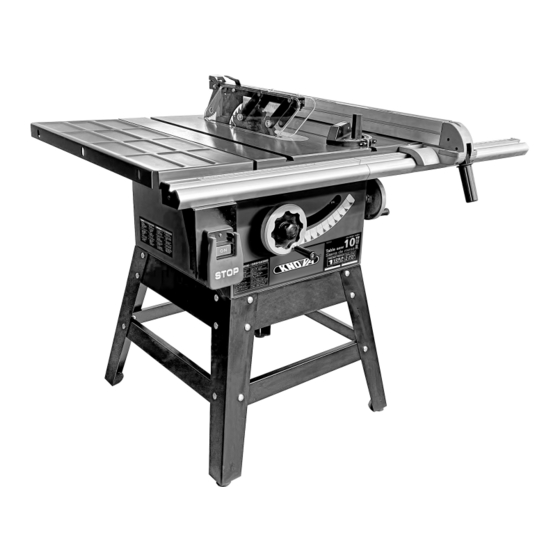
KNOW YOUR MACHINE Blade cover Extension Handle wing Anti-kickback Miter gauge pawls Front rail Rip fence Rear rail Switch Extension Height wing lock handle Motor cover Height handwheel Rip fence handle Fig. 2-1 with a bevel rip cut. Other cuts require special attachments, OVERVIEW which have detailed instruction to reduce risk of injury and The upper position of the blade projects up through the table,... -
Page 7: Assemble And Adjustments
KNOW YOUR MACHINE RIP FENCE – A sturdy metal fence guides the workpiece and BLADE – This saw is provided with a 64 tooth, 10 in. steel is secured with the rip fence handle. blade. The blade is adjusted with bevel and height hand Grooves run along the top and sides of the rip fence for use wheels on the cabinet. - Page 8 ASSEMBLE AND ADJUSTMENTS Level here Flush here Fig. 4 Fig. 6 REMOVE GREASE FROM THE SAW TOP CHECK HEELING (PARALLELING) OF THE SAW BLADE The protective coating on the saw table top and extension TO THE MITER GAGE GROOVE wings prevents rust from forming during shipping and storage. Remove it by rubbing with a rag dipped in kerosene, mineral See Figures 7 and 8.
- Page 9 ASSEMBLE AND ADJUSTMENTS Saw table Fig. 8 Square Fig. 9 Extension wing Saw table Square • Lift the blade guard. Raise the blade all the way by turning the height hand wheel. Fig. 10 Extension wing • Mark beside one of the saw blade teeth at the front of the blade.
- Page 10 ASSEMBLE AND ADJUSTMENTS Blade 3. Check both sides of the blade with a straight edge touching the teeth as shown in Figure 15: ---If the straightedge touches the riving knife Blade evenly on both sides, go to step 4. washer ---if the straightedge only touches the riving Blade nut knife on one side, go to step 5.
- Page 11 ASSEMBLE AND ADJUSTMENTS Fig. 19 4. Put down the guards(N) as Fig.20 and lock the handle(M), then fix the handle(M) as Fig.21. Fig.17 (set screw for adjusting riving knife) 7. Repeat step 3-7 until the riving knife is centered on the blade and aligned at 90º to the table. 8.
-
Page 12: Adjusting The Miter Gauge
ASSEMBLE AND ADJUSTMENTS The table saw is equipped with a push-button switch that will accept a padlock (not included) for locking the switch in the OFF position. See Fig. 24. To safeguard your machine from unauthorized operation and accidental starting by young children, the use of padlock is necessary. -
Page 13: Assembly Diagram Stand
ASSEMBLY DIAGRAM STAND KN RXW-10M3 ” Table saw Sierra de mesa... -
Page 14: Assembly Diagram Motor
ASSEMBLY DIAGRAM MOTOR KN RXW-10M3 ” Table saw Sierra de mesa... -
Page 15: Part List Of Stand And Motor
PART LIST OF STAND AND MOTOR P a r t N o . D e s c r i p t i o n Q’ty. P a r t N o . D e s c r i p t i o n Q’ty. - Page 16 PART LIST OF STAND AND MOTOR P a r t N o . D e s c r i p t i o n Q’ty. P a r t N o . D e s c r i p t i o n Q’ty.
-
Page 17: Assembly Diagram Blade Cover
ASSEMBLY DIAGRAM BLADE COVER KN RXW-10M3 ” Table saw Sierra de mesa ASSEMBLY DIAGRAM MITER GAUGE KN RXW-10M3 ” Table saw Sierra de mesa... -
Page 18: Part List Of Blade Cover And Miter Gauge
PART LIST OF BLADE COVER AND MITER GAUGE P a r t N o . D e s c r i p t i o n Q’ty. P a r t N o . D e s c r i p t i o n Q’ty. -
Page 19: Assembly Diagram Of The Base
ASSEMBLY DIAGRAM OF THE BASE KN RXW-10M3 ” Table saw Sierra de mesa... -
Page 20: Assembly Diagram Of The Table
ASSEMBLY DIAGRAM OF THE TABLE AND EXTENSION WINGS KN RXW-10M3 ” Table saw Sierra de mesa PART LIST OF THE BASE AND TABLE P a r t N o . D e s c r i p t i o n Q’ty. - Page 21 Ensamble y ajustes ............26 Lista de partes base y mesa ..........32 ESPECIFICACIONES MODELO KN RXW-10M3 Motor: 1-1/2 H.P. 120/240 V. 60 Hz. Max. prof de corte a 90º: 79 mm (3/18”) Calib. de ingletes izq. y der.: 30º...
-
Page 22: Instrucciones De Montaje
NORMAS GENERALES DE SEGURIDAD PARA MAQUINARIA PARA MADERA 13. ASEGURE EL TRABAJO. Utilice prensas “C” o prensas 19. NUNCA SE PARE SOBRE LA MÁQUINA. Se pueden ajustables para sujetar el trabajo, cuando sea posible. Es producir lesiones graves si la máquina se inclina o si la más seguro que usar las manos, siendo mejor dejarlas herramienta de corte se pone en funcionamiento libres para manejar la máquina. -
Page 23: Eléctrico
ELÉCTRICO CABLES DE EXTENSIÓN equipo y un enchufe de conexión a tierra. El enchufe debe Use únicamente cables de extensión de 3 hilos, que tengan estar conectado a una toma de corriente adecuada y clavija a tierra de 3 puntas y receptáculos de 3 polos que conectada a tierra de acuerdo con los códigos y ordenanzas acepten la clavija de la máquina. -
Page 24: Glosario De Términos Para Carpintería
ELÉCTRICO Esta herramienta está diseñada para su uso en un circuito Fig.1.2 que tiene una salida que se parece a la ilustrada en el Es- quema D de la Figura 1.2. La herramienta tiene un enchufe con conexión a tierra que se parece al enchufe ilustrado en Tornillo metálico el Esquema D de la Figura 1.2. -
Page 25: Conozca Su Máquina
GLOSARIO DE TÉRMINOS PARA CARPINTERÍA Manos libres (para sierra de mesa) Peligrosa práctica de Rebajar Una operación de corte para reducir el espesor de hacer un corte sin usar valla o guía de ingletes. Vea las la pieza de trabajo con el fin de hacer piezas más delgadas. Reglas de Seguridad. - Page 26 CONOZCA SU MÁQUINA GUÍA DE CORTE AL HILO - Una valla de metal resistente, DESCRIPCIÓN GENERAL guía la pieza de trabajo y se asegura con la manija de La posición superior del disco se proyecta a través de la la guía de corte. mesa, rodeada de una inserción llamada placa de paso a A lo largo de la parte superior y los lados de la guía de corte través.
-
Page 27: Ensamble Y Ajustes
ENSAMBLE Y AJUSTES MONTAJE DE LOS VOLANTES DE ELEVACIÓN E INCLINACIÓN Y PERILLAS DE BLOQUEO 1. Coloque los volantes en posición sobre los tornillos de elevación e inclinación y asegúrese de enganchar las muescas, a (Fig. 3), en la parte de atrás de cada volante, con los pasadores de rodillo, b (Fig. - Page 28 ENSAMBLE Y AJUSTES COMPROBACIÓN A ESCUADRA DE LAS ALAS ADVERTENCIA DE EXTENSIÓN DE LA MESA El disco de la sierra debe estar paralelo a la ranura de la guía de ingletes para que la madera no se atasque Ver Figuras 9 y 10. o produzca un contragolpe.
- Page 29 ENSAMBLE Y AJUSTES La manija (L) debe mantenerse como en la Fig.13. Cuando instale la cuchilla separadora. Luego fije el mango (L) mediante rotación después de la instalación de la cuchilla separadora como se muestra en la Figura 14. Fig. 14 Fig.
- Page 30 ENSAMBLE Y AJUSTES 2. Tire hacia arriba Fig. 18 los protectores como en Fig. 18. Fig. 16 (verificación de 3. Inserte los protectores en la posición O y P la alineación vertical) del esparcidor como en Fig. 18. 5. Afloje el perno central de la cuchilla separadora y remueva.
-
Page 31: Ajuste Al Calibrador De Ingletes
ENSAMBLE Y AJUSTES Compruebe el ajuste de 45º. Incline el disco con el volante INSTALACIÓN DEL de mano de bisel todo hacia la izquierda. Coloque la INTERRUPTOR: escuadra contra la hoja (asegúrese de que la escuadra no Instale el interruptor en la está... -
Page 32: Diagrama De Montaje Soporte
DIAGRAMA DE MONTAJE SOPORTE (254 mm) -
Page 33: Diagrama De Montaje Motor
DIAGRAMA DE MONTAJE MOTOR KN RXW-10M3 ” Table saw Sierra de mesa... -
Page 34: Lista De Partes Soporte Y Motor
LISTA DE PARTES SOPORTE Y MOTOR N o. d e p a r te D e s c r i p c i ó n Cant. N o . de pa r t e D e s c r i p c i ó n Cant. - Page 35 LISTA DE PARTES SOPORTE Y MOTOR N o. d e p a r te D e s c r i p c i ó n Cant. N o . de pa r t e D e s c r i p c i ó n Cant.
-
Page 36: Diagrama De Montaje Guarda De Disco
DIAGRAMA DE MONTAJE GUARDA DE DISCO KN RXW-10M3 ” Table saw Sierra de mesa DIAGRAMA DE MONTAJE DEL CALIBRADOR DE INGLETES KN RXW-10M3 ” Table saw Sierra de mesa... -
Page 37: Lista De Partes De Guarda Y Calibrador
LISTA DE PARTES DE GUARDA Y CALIBRADOR No. de parte D e s c r i p c i ó n Cant. No . de pa r t e D e s c r i p c i ó n Cant. -
Page 38: Diagrama De Montaje Base
DIAGRAMA DE MONTAJE BASE KN RXW-10M3 ” Table saw Sierra de mesa... -
Page 39: Lista De Partes Base Y Mesa
DIAGRAMA DE MONTAJE MESA Y ALAS EXTENSIÓN KN RXW-10M3 ” Table saw Sierra de mesa LISTA DE PARTES BASE Y MESA No. de parte D e s c r i p c i ó n Cant. No. de parte D e s c r i p c i ó n Cant. - Page 40 www.knova.com.mx...
Need help?
Do you have a question about the KN RXW-10M3 and is the answer not in the manual?
Questions and answers