Table of Contents
Advertisement
Available languages
Available languages
Quick Links
Advertisement
Table of Contents

Related Manuals for KNOVA KN SS-162


Summary of Contents for KNOVA KN SS-162
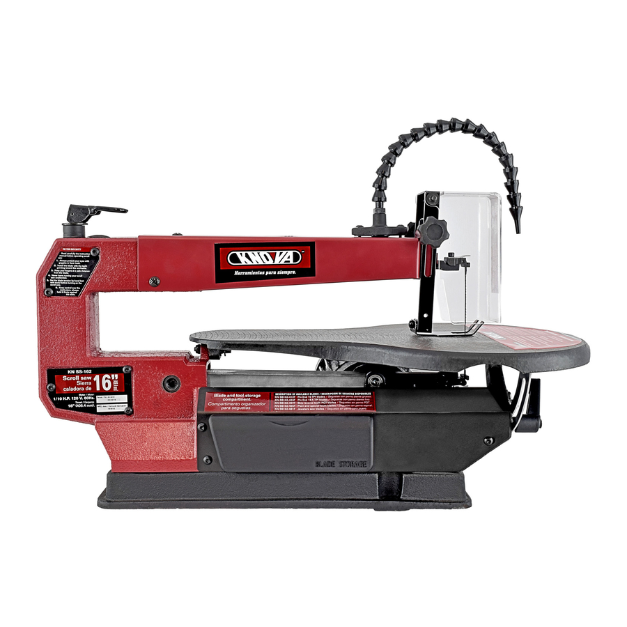
- Page 1 KN SS-162 ” Scroll saw Sierra caladora de KN SS-162...
-
Page 2: Specifications
INDEX Specifications AdjUStMent to align the bevel indicator General safety rules for power tools basic scroll saw operation Additional safety rules for scroll saw Maintenance Unpacking trouble shooting Glossary of terms for woodworking list of parts Motor specifications and electrical requirements Graph of parts Getting to know your scroll saw ASSeMbly Installing dust blower system Installing blade guard Removing and installing blades SPECIFICATIONS Motor: 1/10 H.P. 120 V. 60 Hz. Stroke: 3/4” (19 mm) depth of 90º cut: 2” (50.8 mm) table size: 10” x 17” (254 x 432 mm) depth of 45º cut: 1” (25.4 mm) table tilting: 45º (l / izq. ) throat: 16” (406.4 mm) Machine dimentions: 23-3/8” x 12-1/2” x 13-3/8” (594 x 317.5 x 340 mm) blade lenght: 5” (127 mm) large - width - height ... - Page 3 12. SeCIjRe WORK. Use clamps or a vice to hold work when 20. CHeCK dAMAGed PARtS. before further use of the practical. It is safer than using your hand and it frees both tool, a guard or other part that is damaged should be care- hands to operate tool. fully checked to determine that it will operate properly and perform its intended function check for alignment of moving 13. dOn’t OVeRReACH. Keep proper footing and balance parts, binding of moving parts, breakage of parts, mounting,...
-
Page 4: Unpacking And Checking Contents
12. Use caution when cutting off material that is irregular in 17. turn was “OFF” and remove plug from power supply out- cross section that could pinch the blade before the cut is com- let before installing or removing an accessory or attachment. pleted. A piece of molding for example must lay flat on the table and not be permitted to rock while being cut. 18. Should any part of this scroll saw be missing, bent or fail in any way, or any electrical component fail to perform 13. Use caution when cl1ting off round material such as properly, shut off power switch and remove plug from power dowel rods, or tubing. they have a tendency to roll while be-... -
Page 5: Glossary Of Terms For Woodworking
GLOSSARY OF TERMS FOR WOODWORKING 1. Kerf the slot cut by the blade. 4. blade tooth Set the distance that the edge of the saw blade tooths is bent (on set) outward from the side of the blade. 2. leading edge the edge of the workpiece, which pushed into the blade first 5. trailing edge the work piece edge last cut by the saw blade. 3. Saw blade Path the area of the workpiece directly in line with and moving toward the saw blade edge. 6. Work Piece the Item on which the cutting operations is being performed. Kerf leading edge Workpiece Saw blade Path blade toofth Set trailing edge MOTOR SPECIFICATIONS AND ELECTRICAL REQUIREMENTS this plug requires a mating 3 conductor grounded type outlet WARNING: as shown. -
Page 6: Grounding Lug
Plug power cord into an 110 120V properly grounded type WARnInG: tIHe GReen GROUndInG lUG eXtendInG outlet. If the outlet you are planning to use for this power tool FROM tHe AdAPteR MUSt e3e COnneCted tO A PeR- is of the 2-prong type. dO nOt ReMOVe OR AlteR tHe MAnent GROUnd SUCH AS tO A PROPeFIly GROUnd- GROUndInG PROnG In Any MAnneR. Use an adapter as ed OUtlet bOX nOt All OUtlet bOXed ARe PROPeRly shown below and always connect the grounding lug to known GROUnded. -
Page 7: Guard Assembly
ASSEMBLY Mounting Scroll Saw to Workbench 4. If mounting to a workbench, holes should be drilled through supporting surface of the workbench using dimensions. 1. When mounting the saw to a workbench a solid wood bench is preferred over a plywood bench where noise and vibration Installing dust blower System will be more noticeable. 1. Connect one end of the PVC Hose to the brass tube and 2. Hardware to mount this saw to a workbench is nOt sup- the other end to the of the bellows Seat. plied with the saw. However, we recommend the hardware used be no smaller than the following. 2. Position and tighten the brass tube with Clamp and Knob. 3. For best result, the brass tube should be adjusted to direct Quantity Description air bolt at blade and workpiece. 4 Hex. Head Screws, 1/4 20 x length Required Installing blade Guard 4 Flat Washers, 9/32 I.d. 4 lock washer, g/321.d. 1. locate the blade guard and carefully install it onto the saw as shown the blade guard to frame by bolt washer and Knob. 8 Hex nuts, 1/4 20 nOte: When cutting at angles, the drop foot can be tilted so 3. A soft foam pad to place between your scroll saw and work- it’s parallel to the table and rests flat against the workpiece. bench is nOt supplied with the saw. However, we highly to tilt drop foot, loosen screw, tilt toot so it’s parallel to table recommend the use of such a pad (24”x1 2”x1/2”) to reduce and securely tighten screw. the drop foot should always be... -
Page 8: Removing And Installing Blades
REMOVING AND INSTALLING BLADES a 2 Installing blade WARnInG: to avoid injury from accidental starting I al- ways turn the switch off (“o”) and remove power cord 1. to install the blade, insert the blade through the Access plug from power source before removing or replacing the Hole in the table. (Fig 3) blade. nOte: In order to avoid uncontrollable lifting of the workpiece, the teeth of the blade should always point downward. A. Plain End Blade 2. Insert the blade into the lower blade Holder slot then tight- a 1 Removing blade en set screw. (Fig 4) 1. to remove the blade, loosen tension on blade by first lifting 3. Insert the other end of blade into the upper blade Holder up the Quick Release tension lever. (Fig 1) slot and then tighten set screw. (Fig 4) - Page 9 b. Pin end blade 2 Installin0 the blade note: When installing Pin-end blades, the set screws located 1. Install the blade by inserting one end of the blade through on the upper and lower blade Holders should not be over or the Access Hole in the table and hook the blade pin in the pin under tightened. recess in the lower blade Holder. (Fig 2) the slot must be slightly wider than the thickness of the blade. 2. Check to see that the pins are properly located in the upper After the blade is installed, me blade tension mechanism will and lower blade Holders. keep the Pin end blade in place. 3. to tension blade, lower the Quick Release tension lever. b 1 Removing the blade Check tension on blade, if too tight, turn lever counteclock- wise. (Fig-4) 1. to remove the blade, loosen tension on blade by first lifting up the Quick Release tension lever. (Fig 1) note: H the blade is over tensioned, the lever is difficult to be lowered. 2. Remove blade from the upper and lower blade Holder. (Fig 2) Slightly downward pressure against the upper arm may be helpful when removing blade from the upper blade Holder. (Fig 3) ReleASe tenSIOn QUICK ReleASe ten-...
-
Page 10: To Align The Bevel Indicator
ADJUSTMENT TO ALIGN THE BEVEL INDICATOR 1. loosen the bevel lock handle and move the table until it is approximately perpendicular or at a right angle, to the blade. 2. Use a small square to set the table at 90 degrees to the SQUARe blade. If there is too much space between the square and the blade the table must be adjusted. 3. When the space between the square and blade is minimal tighten the bevel lock handle. the table should now be ap- proximately 90 degrees to the blade. 4. loosen the screw holding the bevel scale pointer and ad- just pointer to O degree. tighten screw. then adjust 0 degree SCAle set screw under the table. -
Page 11: Troubleshooting
TROUBLE SHOOTING WARnInG: For your own safety, turn switch “off” and re- move plug from power source outlet before trouble shoot- ing your scroll saw. PROBLEM CAUSE PROBLEM REMEDY SUGGESTED 1. Wrong tension breaking blades 1. Adjust blade tension. 2. Over working blades. 2. Reduce feed rate. 3. Wrong blade application. 3. Use narrow blades. 4. twisting blade in wood. 4. Avoid side pressure on blade. Motor will not run 1. defective cord or plug. 1. Replace defective parts before using saw again. 2. defective motor. 2. Consult Service Center. Any attempt to repair this motor may create a HAZARd unless repair is done by a qualified service technician. 1. Improper mounting 1. See mounting instructions in this manual for Vibration of saw. -
Page 12: List Of Parts
LIST OF PARTS I.D. Description I.D. Description Size Size 0AM2 ECCENTRIC 0HV9 BALL BEARING 0J4D FLAT WASHER 0AM3 WASHER φ5*10-1 D=φ9.5 , φ5 T=4 0J6U FLAT WASHER 3/16*1/2-3/64 0AM9 BUSH D=φ22 L=29 0J72 FLAT WASHER 0AMH COMPRESSION SPRING 1/4*5/8-1/16 L=16 D=φ10 DW=φ1 N=4.5 0J7F FLAT WASHER 0AMN SHAFT SLEEVE... - Page 13 GRAPH 0F PARTS...
-
Page 14: Especificaciones Del Producto
INDICE especificaciones ensamblaje Reglas de seguridad para las herramientas Ajustes electricas Operacion Reglas de seguridad para las sierras caladoras Soluciones de problemas desempaque y verificación del contenido Mantenimiento Glosario de términos para trabajos en madera lista de partes Información sobre cables de extensión diagrama de partes Conozca su máquina ESPECIFICACIONES DEL PRODUCTO Motor: 1/10 H.P. 120 V. 60 Hz. Carreras: 19 mm (3/4”) Máximo espesor de corte a 90°: 50.8 mm (2”) Mesa de trabajo: 254 x 432 mm (10 x 17”) Máximo espesor de corte a 45°: 25.4 mm (1”) Inclinación de la mesa: 45° a la izquierda Garganta: 406 mm (16”) dimensiones de la máquina: 584 x 318 x 318 mm (23 x 12 1/2 x 12 1/2”) largo de la segueta: 127 mm (5”) (largo x ancho x alto) Golpes por minuto: 1,720 REGLAS DE SEGURIDAD PARA LAS HERRAMIENTAS ELECTRICAS WARnInG: When using electric tools the following basic safety precautions should always be followed to reduce the risk sf fire, eeectric shock and personal injury. - Page 15 14. CUIde SU HeRRAMIentA. Mantenga sus herramientas 21. USe lOS ACCeSORIOS ReCOMendAdOS. Consulte afiladas y limpias para un desempeño mejor y más seguro. Siga el manual del propietario para los accesorios recomendados. las instrucciones para lubricación y cambio de accesorios. el uso de accesorios inadecuados puede generar riesgos. 15. deSCOneCte lA MÁQUInA. Antes de darle servicio o 22. HAGA QUe PeRSOnAl CAlIFICAdO RePARÉ SU MÁ- cuando cambie accesorios. QUInA. esta herramienta eléctrica cumple con las reglas de seguridad relevantes. las reparaciones deben ser realizadas 16. RetIRe lAS llAVeS de AjUSte. Fórmese el hábito de únicamente por personal calificado. Si no se hace así, se pu- verificar que todas las herramientas se retiren de la máquina ede provocar daños considerables al usuario. antes de encenderla. 23. GUARde eStAS InStRUCCIOneS. lea estas instruccio- 17. eVIte el enCendIdO ACCIdentAl. Asegúrese de que nes y guárdelas como guía de operación. el interruptor esté en la posición APAGAdO (OFF) antes de 24. COnSeRVe lAS PROteCCIOneS en SU lUGAR. en conectar la máquina. buenas condiciones y ajústelas.
- Page 16 11. no alimente la pieza muy rápido mientras corta. Hágalo 15. nunca se aleje de la sierra cuando esté encendida, ni a una velocidad suficiente para que la sierra corte. Mantenga antes de que la sierra se detenga completamente. los dedos alejados de la sierra. 16. no ensamble o prepare trabajo sobre la mesa cuando la 12. tenga cuidado al cortar material irregular, puede atorar la sierra esté operando. sierra antes de completar el corte. Un pedazo amoldado debe 17. Apague la máquina y desconéctela antes de instalar o descansar plano sobre la mesa y no se debe permitir que se meza mientras se corta. retirar algún accesorios o aditamento. 13. tenga cuidado al cortar material redondo, ya que tiene 18. en caso de que alguna pieza falte, esté doblada o dañada la tendencia de rodar mientras se corta, ocasionando que la o algún componente eléctrico no funcione correctamente. Ap-...
- Page 17 GLOSARIO DE TERMINOS PARA TRABAJOS EN MADERA 1. Corte – la ranura cortada por la sierra. 4. Acomodo de los dientes de la sierra – la distancia que la punta de los dientes de la sierra están doblados hacia fuera 2. borde inicial – el borde de la pieza de trabajo que es empu- desde el extremo de la sierra. jado primero y hacia la sierra. 5. borde final – el borde de la pieza de trabajo que la sierra 3. trayecto de la sierra – el área de la pieza de trabajo directa- corta finalmente. mente en línea y moviéndose hacia la sierra. 6. Pieza de trabajo – el artículo sobre el cual se realiza el tra- bajo de corte. Corte borde inicial Pieza de trabajo trayecto de la sierra Acomodo de los dientes borde final INFORMACION SOBRE CABLES DE EXTENSION AdVeRtenCIA: no toque con los dedos las terminales de las WARNING: clavijas cuando las conecte o desconecte del contacto. Rating, power supply cord with plug and grounded outlet indi- cated hereby are according to electrical regulations of United States and Canada. For other countries, they may be different. therefore, for the actual electrical rating please see marking on this machine, however for any details of the information on power supply cord with plug and the grounded outlet, please consult a qualified electrical technician.
- Page 18 Conecte el cable a un contacto debidamente aterrizado. Si el Use un adaptador como se muestra y siempre conecte el contacto en el que planea conectar la máquina es de dos ori- adaptador a una tierra conocida. Se recomienda que un elec- ficios, nO QUIte O AlteRe lA PUntA de tIeRRA de nIn- tricista calificado cambie el contacto de dos orificios por uno GUnA FORMA. de tres orificios, debidamente aterrizado. Si no está seguro de que su contacto esté debidamente aterrizado, haga que lo verifique un electricista calificado. nOtA: el adaptador ilustrado se debe usar únicamente si usted cuenta con un contacto de dos orificios debidamente MAKe SURe GROUndInG lUG aterrizado. el uso de cualquier extensión causará alguna pér-...
-
Page 19: Instalación Del Soplador
ENSAMBLE MOntAje de lA SIeRRA CAlAdORA A Un bAnCO de InStAlACIÓn del SOPlAdOR. tRAbAjO. 1. Conecte un extremo de la manguera de PVC al tubo de 1. Cuando monte la sierra a un banco de trabajo, se recomien- bronce y el otro extremo al asiento del fuelle. da usar un banco de madera sólida en lugar de uno de triplay, donde el ruido y la vibración serán menos notorios. 2. Posicione y apriete el tubo de bronce con la prensa y la perilla. - Page 20 INSTALACIÓN Y REMOCIÓN DE SEGUETAS. A.2 Instalación de la segueta. AdVeRtenCIA: Para evitar lesiones por encendido ac- cidental, siempre apague la sierra y desconéctela de la 1. Para instalar la segueta, insértela a través del orificio de corriente eléctrica antes de quitar o cambiar la segueta. acceso en la mesa. (Fig. 3) nOtA: Para evitar levantamiento incontrolable de la pieza de trabajo, los dientes de la sierra deben apuntar hacia abajo. A. Segueta sin pernos. 2. Inserte la segueta en la ranura del sujetador inferior de si- A.1 Para quitar la segueta. erra, luego apriete el tornillo. (Fig. 4) 1. Para quitar la segueta, afloje la tensión de la sierra le- 3. Inserte el otro extremo de la segueta en el sujetador supe- vantando la palanca de liberación rápida. (Fig. 1) rior de sierra y luego apriete el tornillo. (Fig. 4) ejercer una ligera presión hacia abajo en el brazo, superior...
- Page 21 b. Segueta con pernos b-2 Instalación de la segueta. nOtA: Cuando instale seguetas con pernos, los tornillos en 1. Instale la segueta insertando un extremo a través del orifi- los sujetadores superior e inferior no deben estar muy apre- cio de acceso en la mesa y enganchando el perno de la segu- tados ni poco apretados. la ranura debe ser ligeramente más eta en la muesca del sujetador inferior. (Fig. 2) ancha que el espesor de la segueta. Una vez que la segueta se instaló, el mecanismo de tensión de la segueta mantendrá 2. Verifique que los pernos estén bien colocados en los su- la segueta con pernos en su lugar. jetadores superior e inferior. b.1 Para quitar la segueta. 3. Para tensar la segueta, baje la palanca de liberación rápida, si está muy apretada, gire la palanca en sentido contrario a 1. Para quitar la segueta, afloje la tensión de la segueta le- las manecillas del reloj. (Fig. 4) vantando la palanca de liberación rápida. (Fig. 1) nOtA: Si la segueta está muy tensa, la palanca no bajará 2. Retire la sierra de los sujetadores superior e inferior.
- Page 22 AJUSTE PARA ALINEAR EL INDICADOR DEL BISELADO. nOtA: evite colocar el borde de la mesa con- tra la superficie superior 1. Afloje la manija aseguradora de ángulos y mueva la mesa del motor porque puede hasta que esté aproximadamente perpendicular, o en ángulo escuadra causar ruido cuando se recto con la segueta. usa la sierra. 2. Use una escuadra pequeña para colocar la mesa a 90º con la segueta. Si existe mucho espacio entre la escuadra y la segueta, la mesa se debe ajustar. 3. Cuando el espacio entre la escuadra y la segueta es míni- mo, apriete la manija aseguradora de ángulos. la mesa debe estar ahora aproximadamente a 90º con la segueta.
-
Page 23: Soluciones De Problemas
SOLUCIONES DE PROBLEMAS AdVeRtenCIA: Para evitar lesiones por encendidos ac- cidentales. Siempre apague la máquina y desconéctela de la energía eléctrica antes de solucionar problemas de su sierra caladora. ¿QUE ESTA MAL? PROBLEMA ¿QUE HACER? 1. tensión incorrecta. la sierra se rompe. 1. Ajuste la tensión de la sierra. 2. Sierra sobre trabajada. 2. Reduzca la velocidad de alimentación. 3. Incorrecta aplicación de la sierra. 3. Use sierras más delgadas. 4. la sierra se tuerce en la madera. 4. evite presión lateral en la sierra. el motor no arranca. 1. Cable o clavija defectuosos 1. Cambie las partes defectuosas antes de volver a usar la sierra. 2. Motor defectuoso. 2. Consulte al centro de servicio cualquier intento de reparar el motor es peligroso, a menos que se realice por un técnico de servicios calificado 1. Montaje incorrecto de la sierra. Vibración 1. Vea las instrucciones de montaje en este manual para la técnica adecuada de montaje. nOtA: Siempre va a 2. Superficie de montaje inadecuada. -
Page 24: Lista De Partes
LISTA DE PARTES I.D. No. Descripción Medida Cant. I.D. No. Descripción Cant. Medida 0AM2 0HV9 BALERO DE BOLAS EXCÉNTRICO 0J4D 0AM3 ROLDANA PLANA φ5*10-1 ROLDANA D=φ9.5 , φ5 T=4 0J6U 3/16*1/2-3/64 0AM9 BUJE D=φ22 L=29 ROLDANA PLANA 0J72 0AMH ROLDANA PLACA 1/4*5/8-1/16 RESORTE DE COMPRESIÓN L=16 D=φ10 DW=φ1 N=4.5... -
Page 25: Diagrama De Partes
DIAGRAMA DE PARTES... - Page 26 www.knova.com.mx...
Need help?
Do you have a question about the KN SS-162 and is the answer not in the manual?
Questions and answers