Table of Contents
Advertisement
Available languages
Available languages
Quick Links
Advertisement
Chapters
Table of Contents

Related Manuals for KNOVA KN BTS-10N


Summary of Contents for KNOVA KN BTS-10N
- Page 1 ” Table saw with stand Sierra de mesa para madera con base KN BTS-10N...
-
Page 2: Table Of Contents
TABLE OF CONTENTS Product specifications ............1 Assembly and adjustments ..........9 Warning ................1 Operation ................16 Symbols ................1 Maintenance ..............21 Power tool safety ..............2 Troubleshooting guide ............22 Table saw safety ..............3 Push stick pattern ............. 23 Electrical requirements and safety ........ -
Page 3: Power Tool Safety
POWER TOOL SAFETY GENERAL SAFETY INSTRUCTIONS BEFORE USING THIS 14. SECURE WORK. Use clamps or a vise to hold work when practical. It is safer than using your hand POWER TOOL and it frees both hands to operate the tool. Safety is a combination of common sense, staying alert and knowing how to use your power tool. - Page 4 TABLE SAW SAFETY 1. ALWAYS USE SAW BLADE GUARD, riving knife and 16. MOUNT your table saw on a bench or stand before anti-kickback pawls for every through–sawing operation. performing any cutting operations. Refer to ASSEMBLY Through–sawing operations are those in which the blade AND ADJUSTMENT on page 9.
-
Page 5: Electrical Requirements And Safety
TABLE SAW SAFETY SAW BLADE GUARD ASSEMBLY, ANTIKICKBACK b. Do not rip by applying the feed force to the section of the ASSEMBLY AND RIVING KNIFE workpiece that will become the cut-off (free) piece. Feed force when ripping should always be applied between the Your table saw is equipped with a blade guard assembly, anti- saw blade and the fence;... -
Page 6: Preparation
ELECTRICAL REQUIREMENTS AND SAFETY Use a separate electrical circuit for your tool. This circuit must Fig. B Grounding Lug not be less than #12 wire with a 20 A time-lag fuse or a #14 wire with a 15 A time-lag fuse. Make sure this NOTE: When using an extension cord on a circuit with a #14 is connected... -
Page 7: Carton Contents
CARTON CONTENTS UNPACKING YOUR TABLE SAW 3. Separate all parts from the packing material. Check each one with the illustration on below to make certain all items are accounted for before discarding any packing CA UTION To avoid injury from unexpected starting material. -
Page 8: Know Your Table Saw
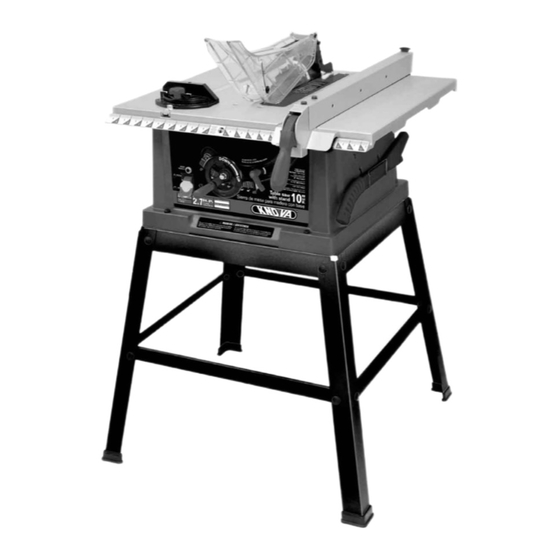
KNOW YOUR TABLE SAW Rip Fence Miter Gauge Blade Tilt Pointer & Scale Overload Reset Switch Blade Bevel Lock Handle ON/OFF Switch Key Stand Riving Knife Blade Guard Anti-kickback Pawls Miter Gauge Slot Table Insert Blade Table Elevation/Tilting Handwheel Push Stick Mounting Holes... -
Page 9: Glossary Of Terms
GLOSSARY OF TERMS ANTI-KICKBACK PAWLS – To prevent the workpiece being RABBET – A notch in the edge of a workpiece. Also called an kicked upward or back toward the front of the table saw by edge dado. the spinning blade. RESAWING –... -
Page 10: Assembly And Adjustments
ASSEMBLY AND ADJUSTMENT ASSEMBLING STAND (Fig. 1) 1. Place the saw (1) on the stand (2). Line up the four holes (3) on the saw base with the holes in the stand top. 1. Unpack all parts and group by type and size. Refer to the NOTE: Make sure front of stand and front of saw are facing Carton Contents. - Page 11 ASSEMBLY AND ADJUSTMENT Fig. 3 2. Remove the arbor nut (2) and outer blade flange (3). (Fig. 6) Square cutout CAUTION Failure to provide the sawdust fallthrough Fig. 6 hole for use of the saw when mounted to a work surface and not the stand will cause sawdust to build up in the motor area, which may result in fire or cause 3.
- Page 12 ASSEMBLY AND ADJUSTMENT 1. Remove the table insert by snapping out from the hole (8). 7. Loosen the blade lock handle (1) and return the blade (Fig. 5) to 0° and lock. 2. Raise the blade to the maximum height by turning the blade 8.
- Page 13 ASSEMBLY AND ADJUSTMENT • Never operate this tool without the blade guard in place for ADDITIONAL BLADE ADJUSTMENTS (Fig. 12) all through sawing operations. NOTE: The adjusting mechanism is located above the blade height adjusting handwheel under the tabletop. If the front •...
- Page 14 ASSEMBLY AND ADJUSTMENT 5. Remove the blade guard assembly by pressing up on the Fig. 13 locking knob (3) and lifting the assembly off the riving knife. (Fig. 14) AVOIDING KICKBACKS (Fig. 16) (Work thrown back towards you) by keeping the blade sharp, the rip fence parallel to the saw blade and by keeping the riving knife, anti-kickback pawls and guards in place, aligned and functioning.
- Page 15 ASSEMBLY AND ADJUSTMENT • Push the handle down and tighten both bolts. 2. If the pointer (3) requires adjustment, loosen the screw under the pointer with a screwdriver. Adjust the pointer to 5. If fence is loose when the handle is in the locked 90°...
- Page 16 ASSEMBLY AND ADJUSTMENT 5. If the blade is not 90° to the table, loosen or tighten C A U T IO N To prevent personal injury: (depending on whether you are increasing or decreasing the degrees) the hex bolt (3) with a 5 mm hex wrench until you achieve 90°.
-
Page 17: Operation
OPERATION BASIC SAW OPERATIONS C A U T I O N To avoid injury, the ON / OFF switch should be in the OFF position and the plug removed RAISE THE BLADE (Fig. 26) from the power source while the cool down takes To raise or lower the blade, turn the blade elevation hand- place, to prevent accidental starting when the reset wheel (1) to the desired blade height, and then tighten the... - Page 18 OPERATION 4. Place the workpiece flat on the table and against the fence. RIPPING SMALL PIECES Keep the workpiece away from the blade. To avoid injury from the blade contact, never make cuts nar- rower than 3/4 in. wide. 5. Turn the saw ON and wait for the blade to come to full speed.
- Page 19 OPERATION Fig. 31 MAKE A PUSH BLOCK (Fig. 33) Making the base: • Start with a 3/8 in. plywood at least 5-1/2 in. wide or wider and 12 in. long or longer. • Cut the piece to shape and size as shown. Making the handle: •...
- Page 20 OPERATION 3. Hold the workpiece firmly against the miter gauge with the 2. Tighten the miter lock handle (3) at 90°. blade path in line with the desired cut location. Move the 3. Hold workpiece (2) firmly against the face of the miter workpiece to a 1 in.
- Page 21 OPERATION USING THE WOOD FACING ON THE RIP FENCE (Fig. 39) DADO CUTS (Fig. 41, 42) When performing some special cutting operations, you can C A U T I O N • Only Stackable dado blades can be add a wood facing to either side of the rip fence (2). used on this saw.
-
Page 22: Maintenance
MAINTENANCE MAINTAINING YOUR TABLE SAW 4. Place a small amount of dry lubricant on GENERAL MAINTENANCE the bevel gear (2). The worm gear (3) CAUTION For your own safety, turn the switch OFF must be kept clean and remove the switch key. Remove the plug from the and free of sawdust, power source outlet before maintaining or lubricating gum, pitch, and... -
Page 23: Troubleshooting Guide
To avoid injury from accidental starting, always turn the switch OFF and unplug the tool before moving, replacing the blade or making adjustments. If for any reason the motor will not run, consult customer service at 01-800-70-KNOVA (56682) PR OBL EM... -
Page 24: Push Stick Pattern
PUSH STICK PATTERN PUSH STICK CONSTRUCTION • Use good quality plywood or solid wood • Use 1/2 in. or 3/4 in. material • Push stick MUST be thinner than the width of material being cut Drill Hole For Hanging Notch To Prevent Hand From Slipping Cut Here To Push 1/2 in. -
Page 25: Parts List
PARTS LIST I.D. No. D e s c r i p t i o n S i z e Qty. I.D. No. D e s c r i p t i o n S i z e Qty. 25AP HEX. SOC. HD. CAP BOLT M6*1.0-25 08VH CORD CLAMP 0901... -
Page 26: Exploded View
EXPLODED VIEW KN BTS-10N ” Table saw with stand Sierra de mesa para madera con base... -
Page 27: Parts List And Exploded View Stand
PARTS LIST AND EXPLODED VIEW STAND STAND I.D. No. D e s c r i p t i o n S i z e Qty. I.D. No. D e s c r i p t i o n S i z e Qty. -
Page 28: Parts List And Exploded View Motor
PARTS LIST AND EXPLODED VIEW MOTOR MOTOR I.D. No. D e s c r i p t i o n S i z e Qty. I.D. No. D e s c r i p t i o n S i z e Qty. -
Page 29: Especificaciones Del Producto
INDICE Especificaciones del producto ........... 28 Ensamblaje y ajustes ............37 Advertencia ............... 28 Funcionamiento ..............44 Simbolos ................28 Mantenimiento ..............49 Seguridad de herramientas eléctricas ......29 Guía para la solución de problemas ........51 Seguridad de la sierra de mesa ........30 Patrón de empujadores ............. -
Page 30: Seguridad De Herramientas Eléctricas
NO SON gafas de seguridad. Las gafas de seguridad están DE UTILIZAR ESTA HERRAMIENTA ELECTRICA disponibles en Knova. La seguridad es una combinación de sentido común, precau- NOTA: Los lentes o las gafas que no cumplan con la norma ción y conocimiento del manejo de la herr mienta eléctrica. -
Page 31: Seguridad De La Sierra De Mesa
SEGURIDAD DE HERRAMIENTAS ELECTRICAS 27. SI EL CORDON DE POTENCIA ES DAÑADO, NO USE 26. UTILICE PROTECCIÓN AUDITIVA para reducir LA HERRAMIENTA. El cordón deberá ser cambiado por el riesgo de pérdida de la audición ocasionada el fabricante o por el centro de servicio autorizado o un por el ruido. - Page 32 SEGURIDAD DE LA SIERRA DE MESA 23. DIRECCION DE AVANCE Haga avanzar la pieza de CONTRAGOLPES trabajo por una hoja o cortador en contra del sentido de CONTRAGOLPES: Los contragolpes pueden ocasionar le- rotación de la hoja o cortador únicamente. siones graves.
-
Page 33: Requisitos Eléctricos Y Seguridad
SEGURIDAD Y REQUISITOS ELECTRICOS INSTRUCCIONES PARA LA CONEXIÓN A TIERRA La Figura 1 muestra un enchufe eléctrico de tres espigas y un tomacorriente con conexión a tierra. Si no dispone de un EN CASO DE QUE EXISTA UNA FALLA EN EL FUNCIONA- tomacorriente adecuadamente conectado a tierra, puede uti- MIENTO O UNA AVERIA, la conexión a tierra proporciona lizar un adaptador (se vende por separado) (Fig. -
Page 34: Preparación
PREPARACION Antes de ensamblar o de hacer funcionar el producto, • Tiempo estimado de ensamble: de 40-60 minutos asegúrese de que todas las piezas estén incluidas. Compare las piezas con la lista de contenidos del empaque y con el • Herramientas necesarias para el ensamblaje y el ajuste: diagrama de la página 34. - Page 35 CONTENIDO DE LA CAJA Seguros contra retroceso Protector de la Ensamblado del hoja y separador cuchilla separadora Ensamblado de la sierra de mesa Pieza de empuje Llaves de sujeción (localizado en de la hoja (2) y Ensamblado del base de llave hexagonal cartabón de ingletes la sierra)
-
Page 36: Conozca Su Sierra De Mesa
CONOZCA SU SIERRA DE MESA Guía de corte en dirección a la veta Cartabón de ingletes Indicador de inclinación y escala de la hoja Interruptor de reinicio por sobrecarga Perilla de sujeción de bisel de la hoja Interruptor de ENCENDIDO/ APAGADO con llave Pedestal... -
Page 37: Glosario De Términos
GLOSARIO DE TERMINOS DISPOSITIVO ANTI-RETROCESO – Evita que la pieza de BLOQUE DE EMPUJE – Se utiliza para la operación de aser- trabajo sea golpeada hacia la parte delantera de la sierra de rado cuando la pieza de trabajo es demasiado estrecha para mesa mediante la hoja giratoria. -
Page 38: Ensamblaje Y Ajustes
ENSAMBLAJE Y AJUSTES ENSAMBLADO DEL PEDESTAL (Fig. 1) MONTE LA SIERRA DE MESA ENSAMBLADA EN EL PEDESTAL (Fig. 2) 1. Desempaque todas las piezas y agrúpelas según el tipo y el tamaño. Vea la lista de piezas para saber cuáles son las PRECAUCION No utilice esta máquina directamente cantidades correctas. - Page 39 ENSAMBLAJE Y AJUSTES 7. Esta apertura permitirá la caída del polvo a través de la 1. Retire el inserto (1) de la mesa sacándolo a presión del base de la sierra. agujero (8). Eleve el bastidor de la hoja hasta la máxima altura, girando la manivela de elevación de la hoja en 8.
- Page 40 ENSAMBLAJE Y AJUSTES Fig. 7 Fig. 8 REMOCION DE LA HOJA (Fig. 5, 7) 4. Cerciórese de que la cuchilla separadora (3) esté en su posición más alta. PRECAUCION Para evitar heridas provocadas por un arranque no intencionado, asegúrese de que el 5.
- Page 41 ENSAMBLAJE Y AJUSTES ALINEACIÓN DE LA CUCHILLA SEPARADORA (Fig. 11) PRECAUCION • Para evitar las lesiones que pudieran ocurrir por la activación accidental, compruebe que el interruptor esté en la posición OFF y el enchufe esté desconectado del tomacorriente que suministra energía. •...
- Page 42 ENSAMBLAJE Y AJUSTES Fig. 15 • Cuando instale el protector de la hoja, cubra los dientes de la hoja con un trozo de cartón doblado para protegerse a sí mismo de posibles lesiones. • Nunca opere esta herramienta sin el protector de seguridad en su lugar para todas las operaciones de corte de lado a lado.
- Page 43 ENSAMBLAJE Y AJUSTES SEPARADOR-LIMITADOR (Fig. 17) AJUSTE DEL INDICADOR DEL SEPARADORLIMITADOR (Fig. 19) 1. Levante la manivela del separadorlimitador (1) 1. El indicador del separador- limitador (6) apunta hacia la Fig. 17 de manera que la escala de medición. La escala muestra la distancia desde el abrazadera de agarre lateral del separador hasta el lado más próximo de la hoja.
- Page 44 ENSAMBLAJE Y AJUSTES NOTA: Para elevar el inserto, gire los tornillos hexagonales Tope de seguridad a 45° en el sentido contrario a las manecillas del reloj, para bajar el 1. Desconecte la sierra del tomacorriente. inserto, gire los tornillos hexagonales en dirección a las mane- cillas del reloj.
-
Page 45: Funcionamiento
ENSAMBLAJE Y AJUSTES 7. Gire la hoja y lleve el diente marcado hacia la parte trasera ALMACENAMIENTO DEL PIEZA DE EMPUJE (Fig. 25) hasta que quede aproximadamente a 1/2 pulg. (12,7 mm) Fije el soporte metálico de almacenaje del pieza de empuje sobre la hoja. - Page 46 FUNCIONAMIENTO OPERACIONES DE CORTE 5. Encienda la sierra y espere a que la hoja adquiera velocidad. Existen dos tipos básicos de corte: corte siguiendo la veta y corte transversal. El primero es un corte que se realiza 6. Incorpore lentamente la pieza de trabajo a la sierra siguiendo la veta de la pieza de trabajo.
- Page 47 FUNCIONAMIENTO CORTES DE PIEZAS PEQUEÑAS EN DIRECCION A LA VETA Para evitar las lesiones por causa del contacto con la hoja, nunca haga cortes más pequeños de 1,9 cm de ancho. 1. Cortar pieza pequeñas en dirección a la veta es inseguro. En lugar de hacer esto, corte en dirección a la veta una pieza de mayor tamaño para obtner el tamaño de la pieza deseada.
- Page 48 FUNCIONAMIENTO HAGA UN BLOQUE DE EMPUJE (Fig. 33) 2. Ajuste la altura de la hoja de manera que quede a 1/8 pulg. (0,32 cm) sobre la parte superior de la pieza de trabajo. Cómo hacer la base: • Comience con madera contrachapada de 3/8 pulg. 3.
- Page 49 FUNCIONAMIENTO 1. Ajuste la hoja (1) según el ángulo deseado y ajuste la Fig. 38 mango de sujeción de bisel de la hoja. 2. Ajuste el mango de sujeción de ingletes (3) a 90°. 3. Sostenga firmemente la pieza de trabajo (2) contra la cara del cartabón de ingletes durante la operación de corte.
-
Page 50: Mantenimiento
FUNCIONAMIENTO 5. Utilice el bloque de empuje (2) para mover la pieza de 3. Las instrucciones para operar la hoja para cortar ranuras trabajo. vienen empacadas con el juego hojas para cortar ranuras, que se compra por separado. NOTA: • Monte la tabla de cantos biselados en la mesa como se 4. - Page 51 MANTENIMIENTO 5. Utilice lavavajillas y agua para limpiar las piezas de plástico. REEMPLAZO DE LAS ESCOBILLAS DE CARBON (Fig. 45) NOTA: Determinados productos químicos de limpieza puede PRECAUCION Siempre desconecte el enchufe del dañar las piezas de plástico. suministro eléctrico antes de inspeccionar las escobillas.
-
Page 52: Guía Para La Solución De Problemas
Para evitar lesiones por encendidos accidentales, APAGUE y desconecte siempre la herramienta antes de moverla, reemplazar las hojas o hacer ajustes. Si por alguna razón el motor no funciona, llame a nuestro Departamento de Servicio al Cliente al 01-800-70-KNOVA (56682). PROBLEMA... -
Page 53: Patrón De Empujadores
PATRÓN DE EMPUJADORES CONSTRUCCION DEL EMPUJADOR • Use madera contrachapada de buena calidad o madera sólida. • Use material de 1/2 pulgada ó 3/4 pulgada. • EI empujador DEBE ser más angosto que el ancho del material que está cortando. Taladre el agujero para colgarlo... -
Page 54: Lista De Piezas
LISTA DE PIEZAS No. de Id. D e s c r i p c i ó n T a m a ñ o Cant. No. de Id. D e s c r i p c i ó n T a m a ñ o Cant. -
Page 55: Diagráma De Partes
VISTA DETALLADA KN BTS-10N ” Table saw with stand Sierra de mesa para madera con base... -
Page 56: Lista De Piezas Y Esquema De La Base
LISTA DE PIEZAS Y ESQUEMA DE LA BASE LISTA DE PIEZAS Y ESQUEMA DE APOYO No. de Id. D e s c r i p c i ó n T a m a ñ o Cant. No. de Id. D e s c r i p c i ó n T a m a ñ... -
Page 57: Lista De Piezas Y Esquema Del Motor
LISTA DE PIEZAS Y ESQUEMA DE MOTOR LISTA DE PIEZAS Y VISTA DETALLADA DEL MOTOR No. de Id. D e s c r i p c i ó n T a m a ñ o Cant. No. de Id. D e s c r i p c i ó n T a m a ñ... - Page 58 www.knova.com.mx...
Need help?
Do you have a question about the KN BTS-10N and is the answer not in the manual?
Questions and answers