Table of Contents
Advertisement
Available languages
Available languages
Quick Links
Advertisement
Chapters
Table of Contents

Related Manuals for KNOVA KN M-3059R


Summary of Contents for KNOVA KN M-3059R
- Page 1 ” Foldable compound miter saw Sierra angular compuesta plegable KN M-3059R...
-
Page 2: Table Of Contents
TABLE OF CONTENTS Table of contents ............... 1 Glossary of terms .............. Product specifications KN M-3059R ........1 Assembly ................Warnings ................1 Adjustments ..............12 Symbols ................1 Operation ................17 Power tool safety ..............2 Crown molding chart ............23 Miter saw safety .............. -
Page 3: Power Tool Safety
POWER TOOL SAFETY GENERAL SAFETY INSTRUCTIONS BEFORE 14. SECURE WORK. Use clamps or a vise to hold work when practical. It is safer than using your hand USING THIS POWER TOOL and it frees both hands to operate the tool. Safety is a combination of common sense, staying alert and knowing how to use your power tool. -
Page 4: Miter Saw Safety
MITER SAW SAFETY SPECIFIC SAFETY INSTRUCTIONS FOR THIS 22. NEVER use the miter saw in an area with flammable MITER SAW liquids or gases. 23. NEVER use solvents to clean plastic parts. Solvents could WARNING To reduce the risk of injury, you must possibly dissolve or otherwise damage the material. -
Page 5: Electrical Requirements And Safety
MITER SAW SAFETY WARNING 40. Do not pick up or carry this saw by the lower blade guard. Doing so could cause damage to the guard. WARNING 41. Do not use this saw to cut fiber cement board. This saw is not intended to cut fiber cement board. -
Page 6: Accessories And Attachments
ACCESSORIES (HSS) and carbide tipped (TCT). While the HSS blades are generally Visit your Knova Hardware Department or see the Knova Power and less expensive than carbide tipped, TCT blades will stay sharper Hand Tool Catalog to purchase recommended accessories for this longer than HSS. -
Page 7: Carton Contents
IMPORTANT: Do not lift miter saw by the trigger switch electric shock, use only identical replacement parts when handle. It may cause misalignment. Lift miter saw only servicing double insulated tools. Call 01-800-70-KNOVA by the carrying handle. (56682) for replacement parts. -
Page 8: Know Your Folding Miter Saw
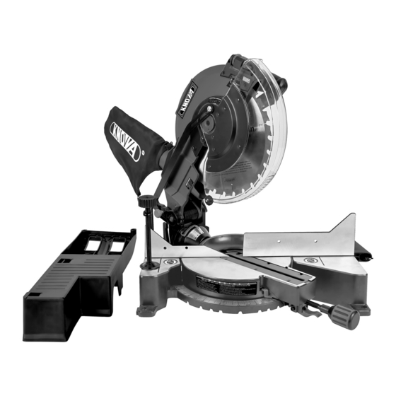
KNOW YOUR FOLDING MITER SAW Laser Vertical Laser Horizontal Adjustment Knob Adjustment Knob Dust Bag Lower Blade Guard Hold-down Clamp Hold-down Latch Bevel Lock Handle Base Fence Mounting Hole Miter Handle Carrying Handle Table Insert Miter scale Support Base (Extension table position) Laser ON/OFF Switch Arbor... -
Page 9: Glossary Of Terms
GLOSSARY OF TERMS AMPERAGE (AMPS) – A measure of the flow of electric cur- POSITIVE STOP LOCKING LEVER – Locks the miter saw at rent. Higher ratings generally means the tool is suited for a preset positive stop for the desired miter angle. heavier use. - Page 10 ASSEMBLY Cutting Positive Safety head Hold-down latch stop bolt lock pin Switch handle Bevel lock handle Detent block Miter handle Fig. B Positive stop locking lever Carrying handle Fig. A Remove saw from support base. Place saw with blade and STEP 6: Tilt the cutting head back to 0°...
- Page 11 ASSEMBLY Fig. H 4. Loosen the bevel lock handle (2), tilt the cutting head towards the left and then turn the detent block (5) clockwise 180° to release the positive stop bolt (7). (Fig. B) 5. Pull out the safety lock pin (3) and grasp the switch handle (4) to lower the cutting head towards the right and down until the pin (3) locks into place.
- Page 12 ASSEMBLY MOUNTING THE MITER SAW (FIG. K) NOTE: To avoid the bevel lock handle interfering with the support base when inserting the saw, pull the bevel lock WARNING handle to the position shown in Fig. M. To avoid injury from unexpected saw movement: REAR •...
-
Page 13: Adjustments
ASSEMBLY Carrying handle CAUTION Do not remove the inner blade collar (8). NOTE: Pay attention to the pieces removed, noting their position and direction they face. Wipe the blade collars clean of any sawdust before installing a new blade. Fig. O Fig. - Page 14 ADJUSTMENT BEVEL STOP ADJUSTMENT 2. Place the blade (7) onto the arbor (9) and against the inner blade collar (8). Then, place the outer blade collar (6) and WARNING To avoid injury from an accidental start, thread the arbor bolt (4) counterclockwise onto the arbor. make sure the switch is in the OFF position and the (Fig.
- Page 15 ADJUSTMENT Fig. U 2. Move the turntable while lifting up on the positive stop lock lever (2) to align the miter scale pointer (3) to the desired degree measurement. 3. If the desired angle is one of the ten positive stops, release the positive stop lock lever (2), making sure the lever snaps into position, and then secure by tightening the miter handle (1).
- Page 16 ADJUSTMENT CUTTING HEAD DOWNWARD TRAVEL ADJUSTMENT supply directly through the power lead. The saw must be (FIG. Y) connected to the power source and the laser on/off switch must be turned on for the laser line to show. Before each cutting operation, check the position of the blade to make sure it does not contact any metal surface.
- Page 17 If the laser line is angled from contact with right to left, turn the knob counterclockwise to align the laser the Knova line parallel with pattern line. Service Centre for replacement. After performing the above adjustments, visually check that both the front and top laser lines are parallel with pattern line.
-
Page 18: Operation
OPERATION SAFETY INSTRUCTIONS FOR BASIC SAW OPERATION • Remove adjusting wrench from the tool before turning it on. WARNING • To reduce the risk of injury, turn unit off • To avoid injury from jams, slips, or thrown pieces, use only and disconnect it from power source before installing recommended accessories. - Page 19 OPERATION • Do not wear loose clothing, gloves, neckties or jewelry • Use only saw blades specifically recommended for (rings, watches). They can get caught and draw you into non-ferrous metal cutting. moving parts. • Do not cut metal workpieces that must be hand held. •...
- Page 20 5. Turn the laser guide on and position the workpiece on the contact Knova or another qualified service dealer. table for pre-alignment of your cut. TURNING THE SAW ON (FIG. GG) WARNING Fig.
- Page 21 OPERATION 2. Loosen the bevel lock handle (3) and position the cutting head at the desired bevel position. Lock the bevel lock handle (3). 3. Turn the Laser guide on and position the workpiece on the table for pre-alignment of your cut. WARNING •...
- Page 22 OPERATION WORKPIECE SUPPORT (FIG. MM) NOTE: This auxiliary fence is used only with Fig. OO Long pieces need extra support. The support should be the saw blade in the 0° placed under the workpiece. bevel position (90° to Keep your hand holding the the table).
- Page 23 OPERATION Fig. QQ Fig. RR Settings for standard crown mold- ing lying flat on compound miter saw Inside table. Corner Workpiece Outside Miter Saw Table Corner Compound cut crown moldings Bevel/Miter Settings NOTE: The chart below references a compound cut for crown molding ONLY WHEN THE ANGLE BETWEEN THE WALLS EQUALS EXACTLY 90°.
-
Page 24: Crown Molding Chart
CROWN MOLDING CHART Compound miter saw Miter and bevel angle settings Wall to crown molding angle 52/38° Crown Molding 45/45° Crown Molding 52/38° Crown Molding 45/45° Crown Molding Angle Angle Between Between Miter Bevel Miter Bevel Miter Bevel Miter Bevel Walls Walls Setting... -
Page 25: Maintenance
MAINTENANCE SAWDUST WARNING To reduce the risk of injury, turn unit off and disconnect it from power source before installing Periodically, sawdust will accumulate under the work table and removing accessories, before adjusting or when and base. This could cause difficulty in the movement of the making repairs. -
Page 26: Troubleshooting Guide
3. Arbor bolt loose. 3. Retighten. See REMOVING OR INSTALLING THE BLADE section. 4. Brushes cracked, damaged, etc. 4. Replace brushes. 5. Other. 5. Contact Knova Service Centre. Motor does 1. Limit switch failure. 1. Replace limit switch. not start. 2. Brush worn. -
Page 27: Parts List
Any attempt to repair or replace electrical parts on this Miter Saw may create a HAZARD un- less repair is done by a qualified service technician. Repair service is available at your nearest Knova Service Centre. I.D. No. - Page 28 PARTS LIST 12 IN. FOLDING COMPOUND MITER SAW I.D. No. I.D. No. D e s c r i p t i o n S i z e Qty. D e s c r i p t i o n S i z e Qty.
-
Page 29: Machine Schematic
MACHINE SCHEMATIC (304.8 mm) -
Page 30: Parts List And Motor Schematic
3STW OIL PAPER 3CS1 STRAIGHT BEVEL GEAR 3SU5 BALL BEARING 3CS2 STRAIGHT BEVEL GEAR 3SU6 BALL BEARING 3GGC COMPRESSION SPRING 3SWW BALL BEARING 3H5A NEEDLE ROLLER 3VP1 MOTOR COVER KN M-3059R ” Foldable compound miter saw Sierra angular compuesta plegable... -
Page 31: Indice
INDICE Indice ................. 30 Glosario de términos ............37 Especificaciones del producto KN M-3059R ..... 30 Ensamble ................38 Advertencia ................ 30 Ajustes ................41 Símbolos ................30 Funcionamiento ..............46 Seguridad en el manejo de herramientas eléctricas ..31 Cuadro para molduras de corona ........ -
Page 32: Seguridad En El Manejo De Herramientas Eléctricas
SEGURIDAD EN EL MANEJO DE HERRAMIENTAS ELECTRICAS INSTRUCCIONES GENERALES DE SEGURIDAD ANTES DE NOTA: Los lentes o las gafas que no cumplan con la norma ANSI UTILIZAR ESTA HERRAMIENTA ELECTRICA Z87.1 podrían ocasionarle graves lesiones si se rompen. La seguridad es una combinación de sentido común, precaución y 13. -
Page 33: Seguridad En La Sierra Inglete
SEGURIDAD EN LA SIERRA DE INGLETE ESPECIFICACIONES DEL MOTOR Y DEL SUMINISTRO 22. NUNCA utilice la sierra para cortar ingletes en un área DE ENERGÍA donde haya líquidos o gases inflamables. 23. NUNCA utilice solventes para limpiar las piezas plásticas. ADVERTENCIA Para reducir el riesgo de herida, debe Los solventes pueden disolver o dañar el material. -
Page 34: Requisitos Eléctricos Y Seguridad
SEGURIDAD EN LA SIERRA DE INGLETE ADVERTENCIA 40. No tome o lleve esta sierra por la guardia de hoja inferior. Si hace así, es possible causar daño a la guardia. ADVERTENCIA 41. No use esta cierra a cortar la tabla de cemento. Esta sierra de inglete no se usa a cortar la tabla de cemento de fibra. -
Page 35: Accesorios Y Acoplamientos
ACCESORIOS Aunque las hojas HSS son más baratos que las carburo Visite la tienda Knova o véase el Catálogo de Herramientas calzado (TCT), la agudeza de las hojas TCT es más larga que Mecánicas y Manuales Knova para comprar los accesorios HSS. -
Page 36: Herramientas Necesarias Para Quitar O Insertar La Hoja / Herramientas Necesaria Para Ajuste
Esto puede hacer que se produzca una aislamiento. LLAME AL 01-800-70-KNOVA (56682) para desalineación. Levante la sierra de inglete solamente piezas de repuesto. -
Page 37: Conozca Su Sierra De Inglete Plegadiza
CONOZCA SU SIERRA DE INGLETE PLEGADIZA Perilla para ajuste Perilla para ajuste vertitcal de laser horizontal de laser Bolsa para polvo Cubierta de la hoja inferior Prensa de sujeción Pestillo de sujecion Manija de sujeción de bisel Base Guía Orificio de montaje Manija para inglete... -
Page 38: Glosario De Términos
GLOSARIO DE TERMINOS AMPERAJE (A) – Es la medición del flujo de corriente TRABA DE RESORTE DE LA MESA DE INGLETES – Traba la eléctrica. Las calificaciones más altas generalmente indican sierra para cortar ingletes en una posición predeterminada, que la herramienta es apropiada para un uso más pesado. para lograr el ángulo de inglete deseado. -
Page 39: Ensamble
ENSAMBLE INSTRUCCIONES DE ENSAMBLAJE A FIN DE AFLOJAR ADVERTENCIA Para reducir el riesgo de herida, pare LA CABEZA CORTADORA (FIG. A, B, C, D, E, F) la máquina y desconecte la misma desde la fuente de fuerza antes de instalar y quitar accesorios y antes ADVERTENCIA Para evitar lesiones, asegúrese de de ajustar o cuando haciendo la reparación. - Page 40 ENSAMBLE INSTALACIÓN EL ENSAMBLE DE DE LA ABRAZADERA ADVERTENCIA • Para reducir el riesgo de herida, DE FIJACIÓN (FIG. H, I) debe desenchufar la sierra desde la fuente de fuerza antes de haber plegado para transporte o almacenaje. ADVERTENCIA CORTAR EL MATERIAL PEQUEÑO •...
- Page 41 ENSAMBLE LA HOJA 1. Base de la sierra ingletadora NOTA: La sierra ingletadora viene con la hoja de sierra instalada. 2. Perno de cabeza hexagonal ADVERTENCIA Asegúrese de que la hoja es instalada correctamente y es apretada antes de 3. Arandela de goma marchar la sierra.
-
Page 42: Ajustes
ENSABLE 1. Nunca lleve la sierra por medio del mango de interruptor, la abrazadera de inglete o la cabeza cortadora. El mango de llevar es apropiado solamente cuando la sierra sea plegada. Cuando la sierra no sea plegada, el bosillo deberá... - Page 43 AJUSTES 6. Baje el cubierta inferior de la hoja (1) a su posición original. 7. Tire el mango principal abajo y arriba algunas veces para confirmar si la guardia de hoja inferior trabaja sin fijación. 8. Asegure que el botón de bloqueo de la pérgola (5) esté liberado para que la hoja pueda girar libremente.
- Page 44 AJUSTES REGULACIÓN DEL TOPE DEL BISEL Ajuste del indicador del bisel de 90° (Fig. U) 1. Cuando la hoja esté exactamente a 90° (0°) respecto de la ADVERTENCIA Para evitar lesiones por encendidos mesa, afloje el tornillo indicador de biselado (1) con un accidentales, asegúrese de que el interruptor esté...
- Page 45 AJUSTES ESCALA DE INGLETES (FIG. W) La báscula de la sierra ingletadora compuesta deslizante se puede leer fácilmente y muestra ángulos de ingletado de 0° a 50° a la izquierda y de 0° a 60° a la derecha. La mesa de la sierra ingletadora tiene las configuraciones de ángulo más comunes con topes positivos a 0°, 15°, 22,5°, 31,6°, 45°...
- Page 46 • No mueva la cerradura desde el interruptor ON/OFF durante cualquier ajustes de laser. NOTA: Si las etiquetas de láser son desaparecidas, dañas o no son claras, ponga contacto con Centro de Servicio Knova EVITE CONTACTO DIRECTO DE OJOS CON LASER para reemplazo.
-
Page 47: Funcionamiento
6. Mirando la tabla desde la parte superior, si el rayo láser no asistencia: está paralelo con la “línea modelo”, siga las instrucciones 01-800-70 a continuación bajo el párrafo “Línea Superior”. KNOVA (56682). VISTA SUPERIOR Rayo Láser Línea de Hoja corte Fig. - Page 48 FUNCIONAMIENTO • Revise y entienda todas las instrucciones de seguridad y ACCESORIOS RECOMENDADOS los procedimientos de utilización indicados en este • Consulte la sección de ACCESORIOS y Manual del operador. (SEGURIDAD Y ACOPLAMIENTOS de este Manual del operador para FUNCIONAMIENTO) obtener información acerca de los accesorios •...
- Page 49 FUNCIONAMIENTO UTILICE VESTIMENTA SEGURA • No use esta sierra para cortar piezas pequeñas. Si para cortar una pieza sus manos o sus dedos quedarían a Cualquier herramienta eléctrica puede despedir y 19 cm o menos de la hoja de la sierra, la pieza de trabajo hacer que se introduzcan en sus ojos objetos es demasiado pequeña.
- Page 50 No a que se detenga, desenchufe la sierra y ponga en fuerce la sierra. contacto con Knova o otro agente de servicio Para comenzar un corte: habilitado. • Coloque las manos al menos a 19 cm del recorrido de la ENCENDIDO DE LA SIERRA (FIG.
- Page 51 FUNCIONAMIENTO 3. Gire la mesa para ingletes hacia la derecha o hacia la 3. La hoja se puede colocar en cualquier ángulo, desde un izquierda con la manija para ingletes. corte recto de 90° (0° en la escala) hasta un corte biselado de 48°...
- Page 52 FUNCIONAMIENTO ADVERTENCIA BASE DE SOPORTE COMO LA MESA DE EXTENSION • Para evitar intervención a la base (FIG. NN) de la sierra de inglete (5) desde el mango cerrador de bisel (4) cuando el ángulo de inglete derecho es más ADVERTENCIA Antes del uso, asegúrese de que la de 30°, tire el mango cerrador de bisel a fin de ajustar...
- Page 53 FUNCIONAMIENTO CORTE DE MOLDURAS DE BASE (FIG. PP) perfectamente a tope contra el techo y contra la pared tienen ángulos que suman exactamente 90°. Las molduras de base y muchas otras molduras pueden cortarse con una sierra compuesta para cortar ingletes. La La mayoría de las molduras de corona tienen un ángulo instalación de la sierra depende de las características y de las superior trasero (la sección que encaja perfectamente a tope...
-
Page 54: Cuadro Para Molduras De Corona
CUADRO PARA MOLDURAS DE CORONA Sierra compuesta para cortar ingletes. Configuraciones del ángulo de ingletes y de bisel. Angulo de la pared respecto de la moldura de corona. Moldura de corona 52/38° Moldura de corona 45/45° Moldura de corona 52/38° Moldura de corona 45/45° Angulo Angulo entre... -
Page 55: Mantenimiento
MANTENIMIENTO ADVERTENCIA ADVERTENCIA Para reducir el riesgo de herida, pare • Cuando limpie el protector inferior, desenchufe la sierra del tomacorriente para evitar la máquina y desconecte la misma desde la fuente de fuerza antes de instalar y quitar accesorios y antes de encendidos inesperados. -
Page 56: Guía Para La Solución De Problemas
3. Vuelva a ajustarlo. Vea la sección EXTRACCION O INSTALACION DE LA HOJA. 4. Los cepillos están partidos, dañados etc. 4. Reemplace los cepillos. 5. Otra. 5. Centro de servicio de Knova. EI motor no 1. Cambie el interruptor de límite.. 1. El interruptor límite falla. arranca. -
Page 57: Lista De Partes
PELIGRO a menos que la reparación sea realizada por un técnico de servicio calificado. El servicio de reparación está disponible en su centro de servicio Knova más cercano. No. de part. - Page 58 LISTA DE PARTES No. de part. No. de part. D e s c r i p c i ó n M e d i d a Cant. D e s c r i p c i ó n M e d i d a Cant.
-
Page 59: Esquema De La Máquina
ESQUEMA DE LA MAQUINA (304.8 mm) -
Page 60: Lista De Piezas Y Esquema Del Motor
3STW PAPEL ACEITADO 3CS1 ENGRANE DE BISEL RECTO 3SU5 BALERO 3CS2 ENGRANE DE BISEL RECTO 3SU6 BALERO 3GGC RESORTE DE COMPRESIÓN 3SWW BALERO 3H5A RODILLO DE AGUJA 3VP1 CUBIERTA DE MOTOR KN M-3059R ” Foldable compound miter saw Sierra angular compuesta plegable... -
Page 61: Notes
NOTES / NOTAS... - Page 62 NOTES / NOTAS...
- Page 63 NOTES / NOTAS...
- Page 64 www.knova.com.mx...
Need help?
Do you have a question about the KN M-3059R and is the answer not in the manual?
Questions and answers