Table of Contents
Advertisement
Available languages
Available languages
Quick Links
Advertisement
Table of Contents

Related Manuals for KNOVA KN SCM-07A


Summary of Contents for KNOVA KN SCM-07A
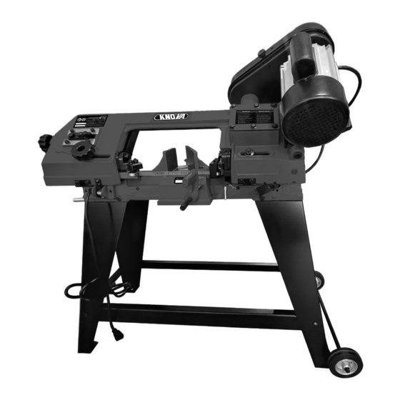
- Page 1 Sierra cinta para metal with stand and wheels / con base y ruedas We invite you to read the user manual before operating your equipment. Lo invitamos a leer el manual del KN SCM-07A usuario antes de operar su equipo.
-
Page 2: Table Of Contents
This tool has many features for making its use more pleasant and enjoyable. Safety, performance, and dependability have been given top priority in the design of this product making it easy to maintain and operate. PRODUCT SPECIFICATIONS MODEL: KN SCM-07A Round cutting capacity: 4-1/2” Height floor to table: 33”... -
Page 3: Specific Safety Instructions The Machine
GENERAL SAFETY INSTRUCTIONS 16. NEVER LEAVE TOOL RUNNING UNATTENDED. 21. BE CAREFUL. Pay attention to what you are doing. TURN POWER “OFF”. Don’t leave tool until it comes Work reasonably. Do not use the machine when to a complete stop. you are tired. -
Page 4: Accessories And Attachments
ACCESSORIES AND ATTACHMENTS RECOMMENDED ACCESSORIES TABLE OF LOOSE PARTS WARNING Unpack carton; check you machine to see parts listed below: : To avoid injury: Band saw • Use only accessories recommended for machine. Stand legs A • Follow instructions that accompany accessories. Stand legs B Use of improper accessories may cause hazards. -
Page 5: Assembly
ASSEMBLY 5. Use the M6-1 x 12 hex bolts, M6-1 hex nuts, 6mm lock washers and 6mm flat washers to install the wheel mounting bracket to legs Cotter 6. Slide the shaft through the holes in the wheel mounting bracket. Slide the wheels onto the shaft on the outside of the mounting bracket, and secure them with the cotter pins To assemble the band saw:... -
Page 6: Adjustments
ASSEMBLY Motor lock bolt The belt tension can be adjusted by adjusting the motor lock bolt. 10. Open the pulley cover, install the key and motor pulley to motor shaft. Install the worm gear pulley on the shaft closest to the gear box. Use a straightedge to check the alignment of the pulley wheels, and adjust them as needed. - Page 7 ADJUSTMENTS 4. BLADE SPEED ADJUSTMENT The band saw is capable of operating at 80, 120, or 200FPM. The speed can easily be adjusted by changing the v-belt placement. Hex bolt on opposite jaw SPEED FEET PER MINUTE 2. BLADE GUIDES ADJUSTMENT Loosen the knob and slide the blade guide as close to To change the blade speeds: the workpiece as possible, then re-tighten the knob.
-
Page 8: Operation
OPERATION HORIZONTAL CUTTING 3. Remove the two flat head screws and the blade guide cover • Use the work stop to quickly and accurately cut multiple pieces of stock to the same length. Blade guide • Clamp the material firmly in the vise jaws to ensure cover a straight cut through the material. -
Page 9: Maintenance
MAINTENANCE MACHINE CARE WARNING : Turn off the machine and disconnect from the power supply before conducting maintenance • Usually check the condition of the power supply cords work or settings. and replace them if they are broken, or even worse if the internal wires are shown. -
Page 10: Part List
PART LIST I.D. No. D e s c r i p t i o n Qty. I.D. No. D e s c r i p t i o n Qty. Worm gear pulley 6mm Flat washer M8 x 8mm Set screw 6mm Lock washer M4 x 8mm Pan head screw M6 x 12mm Pan head screw... - Page 11 PART LIST I.D. No. D e s c r i p t i o n Qty. I.D. No. D e s c r i p t i o n Qty. M8 Hex nut M8 x 20mm Hex head bolt 8mm Lock washer 8mm Flat washer 629ZZ Ball bearing 8mm Lock washer...
- Page 12 PART LIST I.D. No. D e s c r i p t i o n Qty. I.D. No. D e s c r i p t i o n Qty. Rivet M8 x 16mm Carriage bolt Screw support block Long brace 6mm Flat washer Short brace 6mm Lock washer...
-
Page 13: Assembly Diagram
ASSEMBLY DIAGRAM (114.3 mm) - Page 14 ESPECIFICACIONES DEL PRODUCTO MODELO: KN SCM-07A Cap. de corte redondo: 114.3 mm (4-1/2”) Altura de mesa a piso: 838.2 mm (33”)
- Page 15 INSTRUCCIONES GENERALES DE SEGURIDAD 15. COMPRUEBE SI HAY PIEZAS DAÑADAS. Antes de 19. NO utilice herramientas eléctricas en presencia seguir usando la herramienta, se debe revisar de líquidos o gases inflamables. cuidadosamente cualquier protección u otra pieza que 20. NUNCA QUITE GUARDA, DIVISOS DE SEGURIDAD esté...
- Page 16 REQUISITOS ELÉCTRICOS DIRECTRICES PARA CABLES DE EXTENSIÓN ADVERTENCIA : La conexión incorrecta del conductor de puesta a tierra del equipo puede UTILICE UN CABLE DE EXTENSIÓN APROPIADO. resultar en riesgo de descarga eléctrica. El equipo debe estar Asegúrese de que su cable de extensión esté en buenas conectado a tierra mientras está...
- Page 17 ACCESORIOS MONTAJE Para ensamblar la sierra de cinta: 1. Con la ayuda de un asistente, levante la sierra de cinta sobre un soporte adecuado. 2. Fije las patas a la sierra de cinta con pernos hexagonales M8-1,25 x 25, arandelas planas de 8 mm, arandelas de seguridad de 8 mm y tuercas hexagonales M8-1,25.
- Page 18 MONTAJE 4. Levante la sierra de cinta hasta el piso, sujete la abrazadera larga a las patas con los pernos de cabeza redonda M6-1,0 x 16, las arandelas planas de 6 mm, las arandelas de seguridad de 6 mm y las tuercas hexagonales M6-1,0.
- Page 19 MONTAJE Tornillo de ajuste Perno de bloqueo del motor Parada de trabajo La tensión de la correa se puede cambiar ajustando el perno de bloqueo del motor. Tornillo de ajuste 11. Instale el eje del tope de trabajo en el costado de la sierra de cinta y luego bloquéelo en su lugar apretando el tornillo de fijación.
- Page 20 AJUSTES Para cambiar las velocidades de las cuchillas: Afloje el perno de bloqueo del motor para permitir que el motor gire Levante el motor para aliviar la tensión de la correa y coloque la correa en la alineación de polea deseada. Soltar el motor y dejar que su peso tense la correa.
- Page 21 OPERACIÓN CORTE HORIZONTAL 3. Retire los dos tornillos de cabeza plana y la cubierta de la guía de la hoja. • Utilice el tope de trabajo para cortar con rapidez y precisión varias piezas de material del mismo largo. Cubierta de •...
- Page 22 MANTENIMIENTO CUIDADO DE LA MÁQUINA ADVERTENCIA : Apague la máquina y desconéctela de la fuente de alimentación antes de realizar • Por lo general, verifique el estado de los cables de trabajos de mantenimiento o ajustes. alimentación y reemplácelos si están rotos, o peor aún, si se muestran los cables internos.
- Page 23 SOLUCIÓN DE PROBLEMAS PROBLEMA CAUSA SOLUCIÓN Escuadra de • Presión de corte excesiva • Disminuya la presión de corte corte imprecisa • Diente de hoja incorrecto en relación • Elija la hoja adecuada para con la pieza de trabajo la pieza de trabajo •...
- Page 24 LISTA DE PARTES D e s c r i c i ó n Cant. D e s c r i c i ó n Cant. Buje 6202ZZ Cojinete de bolas 629ZZ Cojinete de bolas Sello de aceite Anillo de retención de 9 mm Tapa de cojinete Protector de disco delantero Tornillo de cabeza plana M4 x 8 mm...
- Page 25 LISTA DE PARTES D e s c r i c i ó n Cant. D e s c r i c i ó n Cant. Interruptor Pasador elástico 4 x 25 mm Escala de ángulo Arandela plana de 16 mm Remache Perno de cabeza hexagonal Bloque de soporte de tornillos...
- Page 26 DIAGRAMA DE PARTES (114.3 mm)
-
Page 27: Notes
NOTES / NOTAS... - Page 28 www.knova.com.mx...
Need help?
Do you have a question about the KN SCM-07A and is the answer not in the manual?
Questions and answers