Table of Contents
Advertisement
Quick Links
Advertisement
Table of Contents

Related Manuals for CTS SWH-3112 Series


Summary of Contents for CTS SWH-3112 Series
- Page 1 SWH-3112 Series 12-port L2 Managed Gigabit Fiber Switch User’s Guide Version: 1.1...
-
Page 2: Revision History
This is a Class A product. In a domestic environment, this product may cause radio interference in which case the user may be required to take adequate measures. Trademarks CTS is a registered trademark of Connection Technology Systems Inc All trademarks belong to their respective proprietor Contents subject to change without prior notice. -
Page 3: Cts Contact Information
421 32 Västra Frölunda, Sweden Hirschstettner Straße 19-21/Stiege I Tel: +46-31-221980 A-1220 Vienna, Austria info@ctsystem.se E-mail: Tel: +43-1-235 05 66-0 cts_ce@ctsystem.com E-mail: CTS Connection Technology Systems DE GmbH An den Bergen 17, 60437 Frankfurt am Main, Germany Tel: +491711051295 E-mail: cts_de@ctsystem.com... -
Page 4: Table Of Contents
Table of Contents Revision History ..................ii CTS CONTACT INFORMATION ..............III TABLE OF CONTENTS ................IV CHAPTER 1. INTRODUCTION ..............2 1.1 O SWH-3112 ..............2 VERVIEW OF 1.2 K .................. 3 EATURES 1.3 F & R ................. 5... - Page 5 About this manual In this user’s guide, it will not only clearly introduce CTS SWH-3112 Managed Switch but tell you how to install this Managed Switch with detailed instructions. Organization of the Manual Chapter 1 “Introduction” describes the features of the Managed Switch ...
-
Page 6: Chapter 1. Introduction
Introduction Introduction CTS’s Managed Switch is designed to meet the emerging FTTX & Metro Ethernet requirements. Its low profile appearance with 1U height and the standard rack-mounted size achieve the highest density within a single rack. When massive fiber ports need to be deployed, the Managed Switch provides the best performance and price ratio. -
Page 7: Key Features
Introduction 1.2 Key Features Around 10-inch (26.5 cm), 1U high 8 x 10/100/1000Base-T ports IEEE 802.3/802.3u/802.3ab compliance Support MDI/MDIX/Auto-Crossover Support Auto-Negotiation RJ-45 Slot 4 x 10/100/1000Base-T, 100/1000Base-X Combo ports IEEE 802.3/802.3u/802.3ab/802.3z compliance Support Auto-Negotiation (RJ-45) Support MDI/MDIX/Auto-Crossover (RJ-45) RJ-45 or SFP Slot ... - Page 8 Introduction Management Functions Console Telnet & SSH/CLI RADIUS for authentication SNMP v1/v2c/v3 and network management Private, RFC-1213, RMON MIBs Port mirroring FTP, TFTP, HTTP server and client firmware upgrade TACACS+ for authentication Operation Environment Operating Temperature: 0ºC~50ºC Publication date: April 17, 2020 Revision 1.1...
-
Page 9: Front & Rear Panels
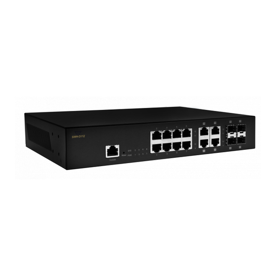
Introduction 1.3 Front & Rear Panels 1.3.1 Front Panel Figure 1-1. SWH-3112 Managed Switch Front Panel The interfaces on the front panel of the Managed Switch are described below: 8 x 10/100/1000Base-T RJ-45 ports (Ports 1-8) 4 x Gigabit combo ports (Ports 9-12): ... -
Page 10: Rear Panel
Introduction 1.3.2 Rear Panel The Managed Switch provides one fixed power module. The type of power module is AC input. Figure 1-2. SWH-3112 Managed Switch Rear Panel The interface on the rear panel of the Managed Switch is described below: Power module and Connector: ... -
Page 11: Led Definitions
Introduction 1.4 LED Definitions The Managed Switch is Plug & Play compliant. The real-time operational status can be monitored through a set of LED indicators located in the front panel. Figure 1-3. LEDs of SWH-3112 Managed Switch Definition Color Operation Device is powered down. -
Page 12: Cable Specifications
Introduction No connection exists. Lit when TP 10/100Mbps port link is up. Green Blinking when TP port is receiving and TP Port Port Status transmitting data at the speed of 10/100Mbps. 1~12 Lit when TP 1000Mbps port link is up. Orange Blinking when TP port is receiving and transmitting data at the speed of 1000Mbps. -
Page 13: Chapter 2. Installation
Installation Installation To properly install SWH-3112 Managed Switch, please follow the procedures listed below. These procedures will be respectively described in detail in the following sections. Installation Requirements Checking the Package Contents Installing the Managed Switch Powering on the Managed Switch ... -
Page 14: Installation Requirements
Installation 2.1 Installation Requirements Basic requirements for installation are as follows: Environmental conditions One power outlet Proper ventilation Proper isolation to electrical noise, radio, etc. UTP cables should not run in the same duct with power and phone line cables ... -
Page 15: Installing The Managed Switch
Installation 2.3 Installing the Managed Switch You can install the SWH-3112 Managed Switch on a flat surface or mount it in a standard 19-inch network equipment rack. CAUTION To prevent any damage or failure of the Managed Switch, please DO NOT block the ventilation holes. -
Page 16: Rack Installation
Installation 2.3.2 Rack Installation In the following section, we will take the SWH-3112 Managed Switch for example to install a 19-inch switch in a standard 19-inch network equipment rack. WARNING! Please mount the Switch firmly in rack, otherwise it may fall and cause the system damage and possible injury to personnel. - Page 17 Installation Step 3. Insert the screws provided in the rack-mount kit through each bracket and into the bracket mounting holes in the switch. Then, tighten the screws with the screwdriver to secure each bracket. (See Figure 2-1) Step 4. Align the mounting holes in the brackets with the desired holes in the rack, and insert screws through each bracket and into the rack.
-
Page 18: Powering On The Managed Switch
Installation 2.4 Powering on the Managed Switch The Managed Switch can be used with AC power supply 100-240 V, 50–60 Hz. After the Managed Switch is turned on, the Power LED indicator should light in green color. For more details about the power LED description, please refer to Section 1.4 LED Definitions. -
Page 19: Installing And Removing Sfp Modules
Installation 2.6 Installing and Removing SFP Modules 2.6.1 Installing SFP Modules To connect the fiber transceiver and LC/SC cable, use the following guidelines: Position the SFP transceiver with the handle on top. 2. Locate the triangular marking in the slot and align it with the bottom of the transceiver. 3. -
Page 20: Connecting The Switch To Console Port
Installation 2.7 Connecting the Switch to Console Port The switch supports a secondary means of management. By connecting the RJ45 to RS232 serial cable between a COM port on your PC (9-pin D-sub female) and the switch’s RJ45 (RJ45) port, a wired connection for management can be established. -
Page 21: Chapter 3. Operation
Operation Operation A built-in management module of Managed Switch provides users flexible interfaces to configure, control and monitor the system remotely and locally. To know the further information about the operation of Managed Switch, please refer to SWH-3112 Network Management User’s Manual for the detailed management functions and required installation and operation procedures. - Page 22 Operation SNMP Management SNMP is also In-Band-Management and requires a network connection to the Managed Switch. The Managed Switch private Management Information Bases (MIB) is provided for SNMP-based network management program to configure, control and monitor the system. Web Management Web Management is done over the network.
-
Page 23: Chapter 4. Maintenance
Maintenance Maintenance This Managed Switch is easy to maintain. The procedures are suggested when you would like to identify faults, perform hardware replacement and firmware upgrade. 4.1 Fault Identification Identifying faults can greatly reduce the times required to find problem and solution. Users may perform local check or remote check to find the problems. -
Page 24: Remote Check
Maintenance 4.1.2 Remote Check Users may check the Managed Switch through SNMP manager remotely. For detailed procedures, please refer to the Network Management User’s Manual. 4.2 Hardware Replacement Procedures WARNING! The Managed Switch contains no user-serviceable parts. DO NOT, UNDER ANY CIRCUMSTANCES, open and attempt to repair it. - Page 25 18F-6, No.79, Sec.1, Xintai 5th Rd., XiZhi Dist., New Taipei City 221, Taiwan(R.O.C) Tel: +886-2-2698-9661 Fax: +886-2-2698-9662 Dir.Line:+886-2-2698-9201 www.ctsystem.com...
Need help?
Do you have a question about the SWH-3112 Series and is the answer not in the manual?
Questions and answers