Table of Contents
Advertisement
Quick Links
IES-3106 SERIES
Managed Industrial Ethernet Switch
IES-3106SFP-DR
4 Ports 10/100/1000Base-T plus 2 Ports 100/1000Base-X
Managed Industrial Ethernet Switch
IES-3106SFP-F1-DR
5 Ports 10/100/1000Base-T plus 1 Port 100/1000Base-X
Managed Industrial Ethernet Switch
IES-3106TP
6 Ports 10/100/1000Base-T Managed Industrial Ethernet Switch
User's Guide
Version 0.96
Advertisement
Table of Contents

Related Manuals for CTS IES-3106 Series


Summary of Contents for CTS IES-3106 Series
- Page 1 IES-3106 SERIES Managed Industrial Ethernet Switch IES-3106SFP-DR 4 Ports 10/100/1000Base-T plus 2 Ports 100/1000Base-X Managed Industrial Ethernet Switch IES-3106SFP-F1-DR 5 Ports 10/100/1000Base-T plus 1 Port 100/1000Base-X Managed Industrial Ethernet Switch IES-3106TP 6 Ports 10/100/1000Base-T Managed Industrial Ethernet Switch User’s Guide...
- Page 2 Trademarks Contents are subject to revision without prior notice. All other trademarks remain the property of their respective owners. Copyright Statement This publication may not be reproduced as a whole or in part, in any way whatsoever unless prior consent has been obtained. FCC Warning This equipment has been tested and found to comply with the limits for a Class-A digital device, pursuant to Part 15 of the FCC Rules.
- Page 3 Revision History Version Date Description 0.90 20140830 First release 0.91 20140929 Some minor fix 0.92 20141126 Add USB automatic firmware and configuration upgrade chapter. 0.93 20141225 Add Bluetooth, DIP switch. 0.94 20150211 Add Non-Blocking Switching Fabric Section 1.1 0.95 20150327 Add USB LED definition Section 3.1 Revise switch description...
-
Page 4: Table Of Contents
Table of Contents 1. OVERVIEW ....................5 1.1 Specification ....................5 1.2 Panel Layout ....................7 2. INSTALLATION ..................10 2.1 Installation Requirements ................10 2.2 Checking the Package Contents..............10 2.3 Installing the Managed Industrial Ethernet Switch......... 11 2.4 Powering the Managed Industrial Ethernet Switch ........12 2.5 Connecting the switch to Network ............... -
Page 5: Overview
1. OVERVIEW Thank you for choosing the Managed Industrial Ethernet Switches. The Managed Industrial Ethernet Switches are designed to meet the massive needs for Fast Ethernet network deployments and aim at Industrial applications that demand wide range of operating temperature. They are fully compliant with IEEE802.3, 802.3u, 802.3x, 802.3z and 802.3ab standards. - Page 6 Non-Blocking Switching Fabric: 12Gbps VLANs: Support up to 128 VLAN Groups Support Tag VLAN Support Q-in-Q VLAN Support IGMP Snooping v1 and v2 Bandwidth Control QoS support 802.1p and ToS Classification Priority Queues: 4 Queues ...
-
Page 7: Panel Layout
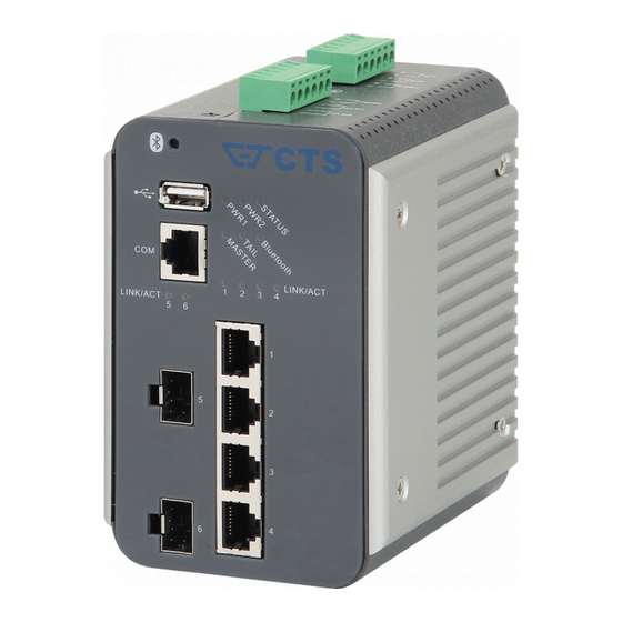
(80km) 1.2 Panel Layout Front Panel ➌ ➎ ➊ ➋ Figure 1. Front Panel for 4 Ports 10/100/1000Base-T + 2 ports 100/1000Base-X ➌ ➎ ➊ ➋ Figure 2. Front Panel for 5 Ports 10/100/1000Base-T + 1 port 100/1000Base-X ➌... - Page 8 ➋ 10/100/1000Mbps RJ-45 port(s) or 100/1000Mbps SFP port(s) ➌ USB host (for more information, please see chapter 4.3) Console port (RJ-45 to RS-232) ➎ LEDs (for more information, please see chapter 3.1) Rear Panel ➏ Figure 4. Rear Panel ➏...
- Page 9 ➐ Reset Button: Insert a pin or paper clip to press the Reset Button for 5 seconds to restart the system Insert a pin or paper clip to press the Reset Button for 10 seconds to reset the device back to factory defaults. ➑...
-
Page 10: Installation
2. INSTALLATION To properly install the Managed Industrial Ethernet Switch, please follow the procedures listed below. Procedures covered in this chapter are described below in separate sections. Installation Requirements Unpacking the Managed Industrial Ethernet Switch Installing the Managed Industrial Ethernet Switch ... -
Page 11: Installing The Managed Industrial Ethernet Switch
If any of the above items is found missing or damaged, please contact your local sales representative for support or replacement. 2.3 Installing the Managed Industrial Ethernet Switch ATTENTION This product is intended to be mounted to a well-grounded mounting surface, such as a metal panel. -
Page 12: Powering The Managed Industrial Ethernet Switch
Grounding the Managed Industrial Ethernet Switch Grounding helps to limit the effects of noise due to electromagnetic interference (EMI). Be sure to install the ground connection from the ground screw to the grounding surface before connecting devices. Figure 6. Grounding wiring 2.4 Powering the Managed Industrial Ethernet Switch The Managed Industrial Ethernet Switch can be used with DC power 48-54 VDC with 2 terminal blocks. - Page 13 PWR2 PWR1 Tighten the wire-clamping screws to fix DC wires tight using flat-head screwdriver. Wire-clamping screws PWR2 PWR1 ALM1 and ALM2 port fault alarm is a pair of port fault connection on the terminal blocks used to connect alarm devices such as speakers or LEDs to alert users when the F/O port link is disconnected.
- Page 14 ALM1 and ALM2 Wiring Configuration...
- Page 15 DI1 and DI2 digital input is a pair of digital input connection on the terminal blocks used to detects if a voltage is above/below a specific threshold. Digital Input Configuration Insert the positive and negative wires into the “+” and “-” contact on the terminal blocks.
- Page 16 Insert positive or negative wire as indicated Use flat-head screwdriver to loosen or tighten the screw...
-
Page 17: Connecting The Switch To Network
2.5 Connecting the switch to Network Connect to Network This Managed Industrial Ethernet Switch has 2 uplink ports (RJ-45 or SFP, please refer to ordering information) and 4 downlink 10/100/1000Mbps RJ-45 ports for you to implement it in your Industrial environment. All RJ-45 ports can be inserted by 10/100/1000Base-T cables, connecting to the end devices. -
Page 18: Bluetooth Hardware Configuration
2.6 Bluetooth Hardware Configuration Accessing “pairing” mode Press “Bluetooth” button for 5 seconds approximately using paper clip or pin. If user releases the button, IES-3106 will stays in pairing mode for 30 seconds. NOTE: Press button for 5 seconds approximately until LED turns GREEN Besides pressing Bluetooth button to access pairing mode, IES-3106 itself periodically turn into pairing mode. -
Page 19: Operation
3. OPERATION The Managed Industrial Ethernet Switch is Plug & Play compliant. Real-time operational status can be monitored through a set of LED indicators located on the top panel. A built-in management module provides users with flexible interfaces to configure, control and monitor the complete system remotely. -
Page 20: Dip Switch Settings
orange blink in turn Orange blinks Fail to access pairing mode. triple times Port link is down Green Link is up and works at 10 or 100Mbps. Green LINK/ACT Receiving and transmitting data. Port Status Blinking Orange Link is up and works at 1000Mbps. Orange Receiving and transmitting data. -
Page 21: Maintenance
4. MAINTENANCE It is easy to use and maintain this Managed Industrial Ethernet Switch. The procedures are suggested when you want to identify faults, perform hardware replacement and firmware upgrading. 4.1 Fault Identification Identifying faults can greatly reduce the time required to find the problem and solution. Users may perform local or remote checks to find the problems. -
Page 22: Hardware Replacement Procedures
(Logic unit number, LUN) File system : FAT12, FAT16, FAT32, NTFS3.1(read-only) and before Automatic Firmware and Configuration Upgrade Process Preparation steps before inserting the USB disk Rename the firmware name as: cts-fw-<model_name>.<admin_user>.<password> Rename the configuration file name as: cts-cfg-<model_name>.<admin_user>.<password>... - Page 23 Firmware Upgrade Firmware upgrade Plug in USB disk and reboot* Upgrade Complete Configuration Upgrade Configuration upgrade and reboot** *Firmware upgrade process would be skipped if: The firmware file is not authorized (wrong admin/password or unauthorized) File too big (>16MB) ...
Need help?
Do you have a question about the IES-3106 Series and is the answer not in the manual?
Questions and answers