Table of Contents
Advertisement
Quick Links
SWH-3109 SERIES
8 PORTS 10/100/1000BASE-T MANAGEMENT ETHERNET
SWITCH WITH 1 PORT 1000BASE-X UPLINK OR 1 PORT
8 PORTS 10/100/1000BASE-T MANAGEMENT ETHERNET
SWITCH WITH 1 PORT 1000BASE-X UPLINK OR 1 PORT
100/1000BASE-X UPLINK WITH BATTERY CHARGING
100/1000BASE-X UPLINK
FUNCTION
User's Guide
Version 0.91
Advertisement
Table of Contents

Subscribe to Our Youtube Channel
Related Manuals for CTS SWH-3109 Series


Summary of Contents for CTS SWH-3109 Series
- Page 1 SWH-3109 SERIES 8 PORTS 10/100/1000BASE-T MANAGEMENT ETHERNET SWITCH WITH 1 PORT 1000BASE-X UPLINK OR 1 PORT 100/1000BASE-X UPLINK 8 PORTS 10/100/1000BASE-T MANAGEMENT ETHERNET SWITCH WITH 1 PORT 1000BASE-X UPLINK OR 1 PORT 100/1000BASE-X UPLINK WITH BATTERY CHARGING FUNCTION User’s Guide...
- Page 2 Revision History Version Date Description 0.90 20150316 First Release 0.91 20150420 Remove 9 ports 10/100/1000 base-T model...
- Page 3 Trademarks CTS is a registered trademark of Connection Technology Systems Inc. Contents subject to revision without prior notice. All other trademarks remain the property of their respective owners. Copyright Statement Copyright 2011 Connection Technology Systems Inc., All Rights Reserved.
-
Page 4: Table Of Contents
Table of Contents 1. INTRODUCTION ................... 5 1.1 The Managed Ethernet Switch ..............5 1.2 Appearance ....................6 1.3 Network Management ................9 2. INSTALLATION ................... 11 2.1 Installation Requirements ............... 11 2.2 Checking the Package Contents ............11 2.3 Installing the Managed Switch ..............12 2.4 Powering ON .................. -
Page 5: Introduction
1. INTRODUCTION Thank you for choosing the 8 Ports 10/100/1000Base-T plus 1 Port 1000Base-X or 100/1000Base-X Uplink Management Ethernet Switch. The Managed Switch can provide the best performance and price ratio when multiple copper ports need to be deployed in networking environment. 1.1 The Managed Ethernet Switch This compact Managed Switch with an eye-catching pearl-white box has 8 10/100/1000Mbps RJ-45 on the front panel. -
Page 6: Appearance
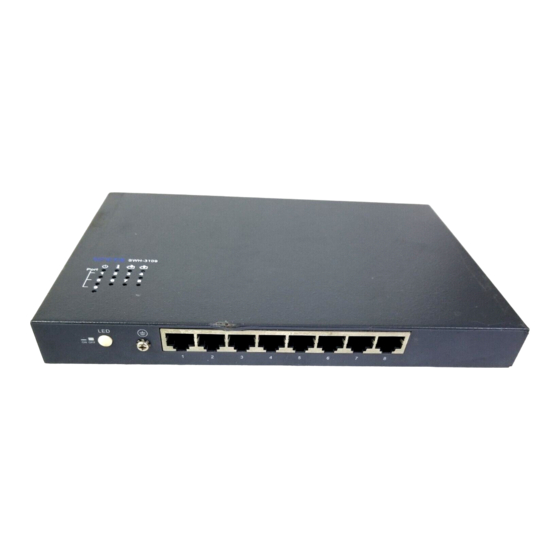
Priority Queues: 4 Queues Management: Telnet/SNMP/Web interface Storm Control DHCP Client DHCP Auto-Provisioning Text Based Config SFF-8472 (digital diagnostic management interface for SFP) Power Down Trap RMON: FTP/TFTP upgrade 1.2 Appearance Front Panel ➋... - Page 7 Rear Panel ➍ ➎ Figure 2. Rear Panel for 8 Ports 10/100/1000Base-T plus 1 Port 1000Base-X or 100/1000Base-X Uplink Management Ethernet Switch with Battery Charging Module (metal housing) ➍ Back-up Battery Socket (optional, and for DC12V Battery only) ➎ 100/1000Mbps or 1000Mbps F/O Port Note: * Back-up Battery Socket is for the BAT models only.
- Page 8 Left and Right Panel (Metal Housing) (Metal Housing) ➏ ➐ Figure 3. Left Panel Figure 4. Right Panel ➏ Power Jack Connector ➐ Reset Button: Insert a pin or paper clip to press the Reset Button for 5 seconds to restart the system ...
-
Page 9: Network Management
Cable Specifications The following table contains various cable specifications for the Managed Switch. Please make sure that you use the proper cable when connecting the Managed Switch. Cable Type Description UTP Category 3, 4, 5 (100 meters max.) 10Base-T EIA/TIA- 568 150-ohm STP (100 meters max.) UTP Cat. - Page 10 (MIB) is provided for SNMP-based network management program to configure, control and monitor the system. Web Management Web Management is done over the network. Once the Managed Switch is available on the network, you can login and monitor the status of it through a web browser remotely or locally.
-
Page 11: Installation
2. INSTALLATION To properly install the Managed Switch, please follow the procedures listed below. Procedures covered in this chapter are described below in separate sections. Installation Requirements Unpacking the Managed Switch Installing the Managed Switch Powering on the Managed Switch ... -
Page 12: Installing The Managed Switch
2.3 Installing the Managed Switch CAUTION To prevent any damage or failure of the Managed Switch, please DO NOT block the ventilation FAN holes. Use the following guidelines when choosing a place to install the Switch: Firm and steady flat surface. ... -
Page 13: Connecting The Switch To Network
2.5 Connecting the Switch to Network Connect to Network This Managed Switch has 8 10/100/1000Mbps RJ-45 ports on the front panel. These ports can be inserted by 10/100/1000Base-T cables, connecting to the end devices. The connection of the fiber port on the rear panel must be matched, i.e. -
Page 14: Operation
3. OPERATION The Managed Switch is Plug & Play compliant. Real-time operational status can be monitored through a set of LED indicators located on the top panel. A built-in management module provides users with flexible interfaces to configure, control and monitor the complete system remotely. 3.1 LED Definitions Definition Color... -
Page 15: Maintenance
4. MAINTENANCE It is easy to use and maintain this Managed Switch. The procedures are suggested when you want to identify faults, perform hardware replacement and firmware upgrading. 4.1 Fault Identification Identifying faults can greatly reduce the time required to find problem and solution. -
Page 16: Hardware Replacement Procedures
4.2 Hardware Replacement Procedures WARNING! The Managed Switch contains no user-serviceable parts. DO NOT, UNDER ANY CIRCUMSTANCES, open and attempt to repair it. Failure to observe this warning could result in personal injury or death from electrical shock. Failure to observe the above warning will immediately void any Warranty. 4.3 Firmware Upgrade This Managed Switch may perform firmware upgrading when required.
Need help?
Do you have a question about the SWH-3109 Series and is the answer not in the manual?
Questions and answers