
Related Manuals for CTS FOS-3128 Series


Summary of Contents for CTS FOS-3128 Series
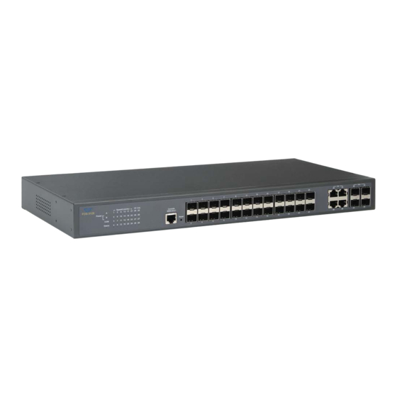
- Page 1 FOS-3128 Series 28-port L2+ Managed Gigabit Fiber Switch Network Management User’s Manual Version 1.0...
- Page 2 Revision History Version Date Description 0.90 1.00.00 20150319 Fisrt release Add HTTP upgrade, DHCP Option 82 0.91 1.00.03 20150707 Suboption 0.91 1.00.05 20150721 Add CPU & Memory Statistics status Revise loop detection (Section 4.4.15) Add port isolation (Section 4.4.12.4) 0.91 1.00.0A 20151228 Add Statistics polling port and interval...
- Page 3 Trademarks CTS is a registered trademark of Connection Technology Systems Inc.. Contents are subject to revision without prior notice. All other trademarks remain the property of their owners. Copyright Statement Copyright Connection Technology Systems Inc.. This publication may not be reproduced as a whole or in part, in any way whatsoever unless prior consent has been obtained from Connection Technology Systems Inc..
-
Page 4: Table Of Contents
Table of Content Chapter 1. INTRODUCTION ....................9 1.1 Management Options ....................9 1.2 Management Software ....................10 1.3 Management Preparations ..................11 Chapter 2. Command Line Interface (CLI)................ 13 2.1 Using the Local Console ..................... 13 2.2 Remote Console Management - Telnet ..............14 2.3 Navigating CLI ...................... - Page 5 2.6.10 LLDP Command ....................55 2.6.11 Loop Detection Command.................. 57 2.6.12 l2protocol-tunnel Command ................60 2.6.13 MAC Command ....................63 2.6.14 Management Command ..................65 2.6.15 Mirror Command ....................67 2.6.16 NTP Command ....................67 2.6.17 QoS Command ....................69 2.6.18 Security Command ....................
- Page 6 4.3.7 Trap Configuration ..................... 151 4.3.8 Syslog Configuration ..................153 4.4 Switch Management ....................154 4.4.1 Switch Configuration ..................155 4.4.2 Port Configuration ....................156 4.4.3 Link Aggregation ....................157 4.4.3.1 Distribution Rule ..................158 4.4.3.2 Port Trunking ....................158 4.4.3.3 LACP Port Configuration ................
- Page 7 4.4.9.5 IGMP Filtering ..................... 195 4.4.10 Static Multicast Configuration ................196 4.4.11 Port Mirroring ....................197 4.4.12 Security Configuration ..................198 4.4.12.1 DHCP Option 82/DHCPv6 Option 37 Settings .......... 200 4.4.12.2 DHCP Option 82 Configuration ..............202 4.4.12.3 DHCP Snooping ..................205 4.4.12.4 PPPoE Configuration ................
- Page 8 4.5.12 IGMP/MLD Monitor ..................243 4.5.12.1 IGMP Snooping Status ................243 4.5.12.2 IGMP Group Table ..................244 4.5.12.3 MLD Snooping Status ................245 4.5.12.4 MLD Group Table ..................245 4.5.13 SFP Information ....................247 4.5.13.1 SFP Port Info ..................... 247 4.5.13.2 SFP Port State ..................
-
Page 9: Chapter 1. Introduction
1. INTRODUCTION Thank you for using the 24 100/1000Mbps SFP ports plus 4 10/100/1000Mbps combo uplink ports Managed Switch that is specifically designed for FTTx applications. The Managed Switch provides a built-in management module that enables users to configure and monitor the operational status both locally and remotely. -
Page 10: Management Software
front panel of the Managed Switch. Direct RJ-45 LAN cable connection between a PC and the Managed Switch is required for Web Management. 1.2 Management Software The following is a list of management software options provided by this Managed Switch: ... -
Page 11: Management Preparations
1.3 Management Preparations After you have decided how to manage your Managed Switch, you are required to connect cables properly, determine the Managed switch IP address and, in some cases, install MIB shipped with your Managed Switch. Connecting the Managed Switch It is very important that the proper cables with the correct pin arrangement are used when connecting the Managed switch to other switches, hubs, workstations, etc.. - Page 12 IP Addresses IP addresses have the format n.n.n.n, (The default factory setting is 192.168.0.1). IP addresses are made up of two parts: The first part (for example 192.168.n.n) refers to network address that identifies the network where the device resides. Network addresses are assigned by three allocation organizations. Depending on your location, each allocation organization assigns a globally unique network number to each network which intends to connect to the Internet.
-
Page 13: Chapter 2. Command Line Interface (Cli)
2. Command Line Interface (CLI) This chapter introduces you how to use Command Line Interface CLI, specifically in: Local Console Telnet Configuring the system Resetting the system The interface and options in Local Console and Telnet are the same. The major difference is the type of connection and the port that is used to manage the Managed Switch. -
Page 14: Remote Console Management - Telnet
2.2 Remote Console Management - Telnet You can manage the Managed Switch via Telnet session. However, you must first assign a unique IP address to the Switch before doing so. Use the Local Console to login the Managed Switch and assign the IP address for the first time. Follow these steps to manage the Managed Switch through Telnet session: Use Local Console to assign an IP address to the Managed Switch Step 1. -
Page 15: General Commands
2.3.1 General Commands This section introduces you some general commands that you can use in User, Privileged, and Configuration modes, including “help”, “exit”, “history” and “logout”. Entering the command… To do this… Available Modes User Mode Obtain a list of available help Privileged Mode commands in the current mode. -
Page 16: Command Format
2.3.3 Command Format While in CLI, you will see several symbols very often. As mentioned above, you might already know what “>”, “#” and (config)# represent. However, to perform what you intend the device to do, you have to enter a string of complete command correctly. For example, if you want to assign IP address for the Managed Switch, you need to enter the following command with the required parameter and IP, subnet mask and default gateway: IP command syntax:... -
Page 17: Login Username & Password
Example 2: specifying three values (separated by commas) Switch(config)#qos 802.1p-map 1,3 0 Switch(config)#qos dscp-map 10,13,15 3 Example 3: specifying a range of values (separated by a hyphen) Switch(config)#qos 802.1p-map 1-3 0 Switch(config)#qos dscp-map 10-15 3 2.3.4 Login Username & Password Default Login When you enter Console session, a login prompt for username and password will appear to request a valid and authorized username and password combination. -
Page 18: User Mode
2.4 User Mode In User mode, only a limited set of commands are provided. Please note that in User mode, you have no authority to configure advanced settings. You need to enter Privileged mode and Configuration mode to set up advanced functions of the Switch. For a list of commands available in User mode, enter the question mark (?) or “help”... -
Page 19: Privileged Mode
2.5 Privileged Mode The only place where you can enter the Privileged mode is in User mode. When you successfully enter the Privileged mode (this mode is password protected), the prompt will be changed to Switch# (the model name of your device together with a pound sign). Enter the question mark (?) or help command to view a list of commands available for use. -
Page 20: Firmware Command
[user_name] | startup ] startup [password] [user_name] Enter the username for FTP server login. [password] Enter the password for FTP server login. Switch# copy-cfg to [A.B.C.D | Enter the IP address of your TFTP server. tftp [A.B.C.D | A:B:C:D:E:F:G:H] A:B:C:D:E:F:G:H] [file name] Enter the configuration file name that you want to [file_name] [running... -
Page 21: Ip Command
2.5.3 IP Command Command Parameter Description Switch# ip address DHCP release packets and Discover packets will dhcp recycle be sent to DHCP server in a manual way. And it will ask for IP address from DHCP server again. Note 1: Need to enable “IPv4 DHCP Auto Recycle”... -
Page 22: Write Command
A:B:C:D:E:F:G:H] [- [-h (1-100)hops] Specify max hops between the local host and the h (1-100)hops] remote host Example Switch# traceroute 8.8.8.8 Switch# traceroute 8.8.8.8 –h 30 Switch# ping 2001:4860:4860::8888 Switch# ping 2001:4860:4860::8888 –h 30 2.5.7 Write Command To save running configurations to startup configurations, enter the write command. All unsaved configurations will be lost when you restart the Managed Switch. - Page 23 System Location: Display a brief location description for this Managed Switch. Use “switch-info system-location [sys_location]” command to edit this field. DHCP/DHCPv6 Vendor ID: Display the Vendor Class Identifier used for DHCP/DHCPv6 relay agent function. Use “switch-info dhcp-vendor-id [dhcp_vendor_id]” command to edit this field. Model Name: Display the product’s model name.
- Page 24 6. Show ARP Show ARP information. Refer to “show arp command” section.
-
Page 25: Configuration Mode
2.6 Configuration Mode When you enter “configure” or “config” and press “Enter” in Privileged mode, you will be directed to the Global Configuration mode where you can set up advanced switching functions, such as QoS, VLAN and storm control security globally. All commands entered will apply to running-configuration and the device’s operation. -
Page 26: No Command
Switch(config)# interface 1-3 Enter three continuous interfaces. Use a Switch(config-if-1-3)# hyphen to signify a range of interface numbers. In this example, interface 1, 2, and 3 will apply commands entered. Switch(config)# interface 1,3-5 Enter a single interface number together with Switch(config-if-1,3-5)# a range of interface numbers. - Page 27 Current Boot Image: The image that is currently using. Configured Boot Image: The image you would like to use after rebooting. Image-1 Version: Display the firmware version 1 (image-1) used in this device. Image-2 Version: Display the firmware version 2 (image-2) used in this device. M/B Version: Display the main board version.
-
Page 28: Acl Command
2.6.4 ACL Command Command Parameter Description Switch(config)# acl [1-192] [1-192] The total number of ACL rule can be created is 192. Use this command to enter ACL configuration mode for each ACL rule. When you enter each ACL rule, you can further configure detailed settings for this rule. - Page 29 Switch(config-acl-RULE)# Specify source IPv4 address as “ANY”. source-ipv4 any Switch(config-acl-RULE)# [A.B.C.D] Specify source IPv4 address. source-ipv4 address [A.B.C.D] [0-255.X.X.X] [0-255.X.X.X] Specify source IPv4 mask. Switch(config-acl-RULE)# Specify source IPv6 address as “ANY”. source-ipv6 any Switch(config-acl-RULE)# [A:B:C:D:E:F:G:H] Specify source IPv6 address. source-ipv6 address [A:B:C:D:E:F:G:H] [10~128] Specify source IPv6 prefix-length.
- Page 30 Switch(config-acl-RULE)# Reset IPv4 protocol and IPv6 next no protocol header back to the default “ANY”. Switch(config-acl-RULE)# Disable rate limitation. no rate-limit Switch(config-acl-RULE)# Reset source IPv4 address back to the no source-ipv4 default (ANY). Switch(config-acl-RULE)# Reset source IPv6 address back to the no source-ipv6 default (ANY).
-
Page 31: Archive Command
2.6.5 Archive Command Command Parameter Description Switch(config)# archive Enable the auto-backup configuration auto-backup files function. Switch(config)# archive [A.B.C.D | Specify the IP/ IPv6 address of the auto-backup path ftp A:B:C:D:E:F:G:H] FTP server. [A.B.C.D | [file_directory] Specify the file directory of the FTP A:B:C:D:E:F:G:H] server to save the start-up [file_directory] [user_name]... -
Page 32: Channel-Group Command
2.6.6 Channel-group Command 1. Configure a static link aggregation group (LAG). Command Parameter Description Switch(config)# channel-group [group_name] Specify a name for this link trunking [group_name] aggregation group. Switch(config)# interface [port_list] [port_list] Use “interface” command to [group_name] configure a group of ports’ link Switch(config-if-PORT-PORT)# aggregation link membership. - Page 33 Show command Switch(config)# show channel-group Show link aggregation settings. trunking Switch(config)# show channel-group [trunk_name] Show a specific link aggregation trunking [trunk_name] group’s settings including aggregated port numbers and load-balancing status. Below is an example of creating a static link aggregation group (port trunking group) using Channel-group commands to have the users realize the commands we mentioned above in this section.
- Page 34 port_list STEP9 interface Speciy the interface that you would like to set to Trunking Group. Example: FOS-3128(config)# interface 1,3 FOS-3128(config-if-1,3)# STEP10 group_name channel-group trunking In this example, it configures Port 1 and Port 3 as the link membership Example: of “CTSGROUP”Trunking FOS-3128(config-if-1,3)# channel-group trunking CTSGROUP Group OK !
- Page 35 2. Use “Interface” command to configure link aggregation groups dynamically (LACP). Channel-group & Interface Parameter Description command Switch(config)# interface [port_list] [port_list] Enter several discontinuous port numbers separated by commas or a range of ports with a hyphen. For example:1,3 or 2-4 Switch(config-if-PORT-PORT)# Enable LACP on the selected channel-group lacp...
- Page 36 Below is an example of creating a dynamic link aggregation group using Channel-group commands to have the users realize the commands we mentioned above in this section. Command Purpose STEP1 configure Enter the global configuration mode. Example: FOS-3128# config FOS-3128(config)# STEP2 channel-group distribution-rule source-ip Enable Source IP Address...
- Page 37 STEP10 channel-group lacp role active In the Example 1, it configures LACP Port [no channel-group lacp role] 5~7 as “Active” in LACP Role. Example 1: FOS-3128(config-if-5-7)# channel-group lacp role active In the Example 2, it OK ! configures LACP Port Example 2: 5~7 as “Passive”...
-
Page 38: Dot1X Command
2.6.7 Dot1x Command Command Parameter Description Switch(config)# dot1x Enable IEEE 802.1X function. When enabled, the Managed Switch acts as a proxy between the 802.1X-enabled client and the authentication server. In other words, the Managed Switch requests identifying information from the client, verifies that information with the authentication server, and relays the response to the client. - Page 39 Show command Switch(config)# show dot1x Show 802.1X system configuration. Switch(config)# show dot1x Show each interface’s 802.1X interface configuration. Switch(config)# show dot1x [port_list] Show the specified interfaces’ interface [port_list] 802.1X configuration. Switch(config)# show dot1x Show each port’s 802.1X statistics. statistics Switch(config)# show dot1x [port_list] Show the specified interfaces’...
- Page 40 Switch(config-if-PORT-PORT)# Re-authenticate the selected dot1x reauthenticate interfaces right now. No command Switch(config)# interface [port_list] [port_list] Enter several discontinuous port numbers separated by commas or a range of ports with a hyphen. For example:1, 3 or 2-4. Switch(config-if-PORT-PORT)# no Reset the selected interfaces’ dot1x port-control 802.1X port type back to the default (authorized state).
-
Page 41: Ip Command
2.6.8 IP Command 1. Set up an IP address of the Managed Switch or configure the Managed Switch to get an IP address automatically from DHCP server. IP command Parameter Description Switch(config)# ip enable Enable IPv4 address processing. Switch(config)# ip [A.B.C.D] Enter the desired IP address for your Managed address [A.B.C.D]... - Page 42 3. Enable DHCP/DHCPv6 relay function. IP DHCP Snooping Parameter Description Command Switch(config)# ip dhcp Enable DHCP/DHCPv6 snooping snooping function. Switch(config)# ip dhcp [port_list] Specify DHCP/DHCPv6 server trust snooping dhcp-server port(s). [port_list] Switch(config)# ip dhcp Globally enable DHCP/DHCPv6 server snooping dhcp-server-ip trust IP/IPv6 address.
- Page 43 Switch(config)# no ip dhcp Clear Remote ID description. snooping remote id Switch(config)# no ip dhcp Disable the Formatted Option 82 / snooping formatted DHCPv6 Option 37 Remote Id. Show command Switch(config)# show ip Show DHCP/DHCPv6 snooping dhcp snooping configuration. Switch(config)# show ip Show each port’s DHCP Snooping dhcp snooping interface Option 82/Option 37 and trust port...
- Page 44 [circuit_id] Besides, you can configure the circuit ID to be a string of up to 63 characters. Switch(config-if-PORT-PORT)# Enable the selected interfaces’ DHCP ip dhcp snooping option Option 82 / DHCPv6 Option 37 relay agent. Switch(config-if-PORT-PORT)# Enable the selected interfaces as DHCP ip dhcp snooping trust Option 82 / DHCPv6 Option 37 trust ports.
- Page 45 5. Enable or disable IGMP/MLD snooping globally. IGMP, Internet Group Management Protocol, is a communication protocol used to manage the membership of Internet Protocol multicast groups. IGMP is used by IP hosts and adjacent multicast routers to establish multicast group memberships. It can be used for online streaming video and gaming, and allows more efficient use of resources when supporting these uses.
- Page 46 Switch(config)# ip igmp [port_list] Specify multicast router ports. snooping mcast-router [port_list] Switch(config)# ip igmp [1-6000] Specify the Query time interval of snooping query-interval [1-6000] IGMP/MLD querier. This is used to set up the time interval between transmitting IGMP/MLD queries. (Range:1-6000 seconds) Switch(config)# ip igmp [1-4094]...
- Page 47 6. Configure IGMP filtering policies. IGMP Filtering command Parameter Description Switch(config)# ip igmp filter Globally enable IGMP filtering function. Switch(config)# ip igmp profile [profile_name] Create or modify a profile for IGMP [profile_name] filter. The maximum length of profile name is 20 characters. Up to 60 profiles can be created.
- Page 48 Examples of IGMP Filtering Command Switch(config)# ip igmp filter Enable IGMP filtering function. Switch(config)# ip igmp segment 50 Create a segment “50”. Switch(config-segment-50)# name Silver Specify a name “Silver” for this segment 50. Switch(config-segment-50)# range 224.10.0.2 Specify a multicast IP range 229.10.0.1 224.10.0.2 to 229.10.0.1 to segment Switch(config)# ip igmp profile Silverprofile...
- Page 49 no ip igmp max-groups multicast streams back to the default (512 channels). Switch(config-if-PORT)# no ip [E.F.G.H | Remove this static multicast IP igmp static-multicast-ip E:F:G:H:I:J:K:L] [E.F.G.H | E:F:G:H:I:J:K:L] vlan Note: Only one port could be [1-4094] assigned at a time. [1-4094] Remvoe the specified VLAN ID.
- Page 50 8. Set Up IP Source Binding Function. Command Parameter Description Switch(config)# ip source binding [1-12] Specify the IP/IPv6 address security [1-12] ip-address [A.B.C.D | binding number. A:B:C:D:E:F:G:H] [A.B.C.D | A:B:C:D:E:F:G: Specify IP/IPv6 address. Switch(config)# ip source binding [1-12] Enable the IP/IPv6 address for the [1-12] specified number.
- Page 51 Switch(config-if-PORT)# ip [A.B.C.D | Add a static IP/IPv6 address to static sourceguard static-ip [A.B.C.D A:B:C:D:E:F:G:H] IP address table. | A:B:C:D:E:F:G:H] vlan [1- 4094] Note: Only one port could be assigned at a time. [1-4094] Specify a VLAN ID. Note: Static IP can only be configured when IP sourceguard is set to fixed-ip.
- Page 52 10. Use “Interface” command to configure PPPoE-IA for Security. Only PPPoE server’s packets coming from PPPoE-IA trust port(s) are allowed to be forwarded; otherwise, those packets will be dropped. Command Parameter Description Switch(config)# interface [port_list] Enter several discontinuous port [port_list] numbers separated by commas or a range of ports with a hyphen.
-
Page 53: Ipv6 Command
2.6.9 IPv6 Command Brief Introduction to IPv6 Addressing IPv6 addresses are 128 bits long and number about 3.4×1038. IPv6 addresses are written in eight groups of four hexadecimal digits separated by colons, such as 2001:0db8:85a3:0000:0000:8a2e:0370:7334 IPv6 unicast addresses other than those that start with binary 000 are logically divided into two parts: a 64-bit network prefix and a 64-bit interface identifier. - Page 54 Set up the IPv6 address of the Managed Switch or configure the Managed Switch to get an IP address automatically from DHCPv6 server. IPv6 command Parameter Description Switch(config)# ipv6 Configuration of IPv6 addresses using address autoconfig stateless autoconfiguration. Switch(config)# ipv6 Configure DHCPv6 function into the address dhcp auto auto mode.
-
Page 55: Lldp Command
2.6.10 LLDP Command LLDP stands for Link Layer Discovery Protocol and runs over data link layer. It is used for network devices to send information about themselves to other directly connected devices on the network. By using LLDP, two devices running different network layer protocols can learn information about each other. - Page 56 Show command Switch# show lldp Show LLDP settings. Switch# show lldp interface Show each interface’s LLDP configuraiton. Switch# show lldp interface [port_list] Show the selected interfaces’ LLDP configuration. Switch# show lldp status Show the current LLDP status. Switch(config)# show lldp Show LLDP settings.
-
Page 57: Loop Detection Command
2.6.11 Loop Detection Command In a real network, it is possible the people misconnect the network cable to incur loop condition. In a worst case, the network is out of service thereafter. This section gives a guide to configure the Loop Detection function of the system to prevent the system from loop. - Page 58 1. Be aware that Looped port unlock- interval converted into seconds should be greater than or equal to Detection Interval seconds multiplied by 10. The ‘10’ is a magic number which is for the system to claims the loop detection disappears when the system does not receive the loop- detection packet from itself at least 10 times.
- Page 59 Switch(config)# show loop- [port_list] Show Loop Detection status of the detection status [port_list] specified port(s). Examples of Loop Detection command Switch(config)# loop-detection interval 60 Set the Loop Detection time interval to 60 seconds. Switch(config)# loop-detection unlock-interval 120 Set the Loop Detection unlock time interval to 120 minutes.
-
Page 60: L2Protocol-Tunnel Command
2.6.12 l2protocol-tunnel Command L2PT (Layer 2 protocol tunneling) allows Layer 2 protocol data units (PDUs), including CDP(Cisco Discovery Protocol), LLDP(Link Layer Discovery Protocol), STP(Spanning Tree Protocol), VTP(Vlan Trunking Protocol), LACP(Link Aggregation Control Protocol), PAgP(Port Aggregation Protocol), UDLD(Unidirectional Link Detection), to be tunneled through a network. GBPT, also referred to as Generic Bridge PDU Tunneling, provides a scalable approach to PDU tunneling by software encapsulating the PDUs in the ingress edge switches and then multicasting them in hardware. - Page 61 Switch(config)# show Clear each PDU’s encapsulation and l2protocol-tunnel clear decapsulation counters of all ports. Examples of L2PT command Switch(config)# l2protocol-tunnel Enable L2PT function. Switch(config)# l2protocol-tunnel cos 3 Specify the priority bit value “3” to L2PT Class of Service (CoS). Use “Interface” command to configure Layer 2 protocol data units (PDUs) settings. L2PT &...
- Page 62 Switch(config-if-PORT-PORT)# no Disable point-to-point layer 2 protocol l2protocol-tunnel point-to-point tunneling for PAgP packets on the pagp selected port(s). Switch(config-if-PORT-PORT)# no Disable point-to-point layer 2 protocol l2protocol-tunnel point-to-point tunneling for UDLD packets on the udld selected port(s). Switch(config-if-PORT-PORT)# no Disable layer 2 protocol tunneling for l2protocol-tunnel stp STP packets on the selected port(s).
-
Page 63: Mac Command
2.6.13 MAC Command Set up MAC address table aging time. Entries in the MAC address table containing source MAC addresses and their associated ports will be deleted if they are not accessed within aging time. MAC Command Parameter Description Switch(config)# mac [0-172800s] Enter the aging time for MAC addresses in address-table aging-time... - Page 64 Examples of MAC command Switch(config)# mac address-table aging-time Set MAC address aging time to 200 seconds. Use “Interface” command to configure a group of ports’ MAC Table settings. MAC & Interface command Parameter Description Switch(config)# interface [port_list] Enter several discontinuous port [port_list] numbers separated by commas or a range of ports with a hyphen.
-
Page 65: Management Command
2.6.14 Management Command Command Parameter Description Switch(config)# management Enable Console management. To manage console the Managed Switch via Console. Switch(config)# management [1-10] Configure the retry times if the console console fail-retry [1-10] login fails. The allowable value is 1~10 (times). Switch(config)# management [1-120] Configure the coslole block time of the... - Page 66 Switch(config)# no management Reset Telnet port back to the default. The telnet port default port number is 23. Switch(config)# no management Disable Web management. Switch(config)# no management Reset web timeout value back to the web timeout default (20 minutes). Show command Switch(config)# show management Show the current management configuration of the Managed Switch.
-
Page 67: Mirror Command
2.6.15 Mirror Command Command Parameter Description Switch(config)# mirror [port] Specify the preferred target port (1~28) for destination [port] port mirroring. Switch(config)# mirror source [port_list] Specify a source port number or several [port_list] source port numbers for port mirroring. NOTE: The port selected as the target port cannot be the source port. - Page 68 1=1hour, 2=2hours, 3=3hours, 4=4hours, 5=6hours, 6=8hours, 7=12hours, 8=24hours Switch(config)# ntp time- [0-135] Specify the time zone to which the zone [0-135] Managed Switch belongs. Use space and a question mark to view the complete code list of 136 time zones. For example, “Switch(config)# ntp time- zone ?”...
-
Page 69: Qos Command
2.6.17 QoS Command 1. Set up Qos QoS command Description Parameter Switch(config)# qos [802.1p | dscp] [802.1p | dscp] Specify QoS mode. Switch(config)# qos dscp-map [0- [0-63] Specify a DSCP bit value. 63] [0-7] [0-7] Specify a queue value. Switch(config)# qos management- [0-7] Specify management default priority [0-7]... - Page 70 back to the default. Switch (config-dscp-map-ID)# no Reset the new DSCP bit value new-dscp for the selected priority mapping ID back to the default. Switch (config-dscp-map-ID)# no rx- Reset the received DSCP bit dscp value for the selected priority mapping ID back to the default. Switch(config)# no qos remarking Globally disable 802.1p bit 802.1p...
- Page 71 No command Switch(config-if-PORT-PORT)# no Disable QoS ingress rate limit qos rate-limit ingress setting. Switch(config-if-PORT-PORT)# no Disable QoS egress rate limit qos rate-limit egress setting. Switch(config-if-PORT-PORT)# no Reset the user priority value setting qos user-priority back to the default. For QoS configuration via CLI, we take a FOS-3128 Managed Switch for example to let the users have a clear understanding of these QoS commands.
- Page 72 Below is the complete CLI commands applied to FOS-3128 Managed Switch. Command Purpose STEP1 configure Enter the global configuration mode. Example: FOS-3128# config FOS-3128(config)# STEP2 qos 802.1p In this example, it configures the QoS Mode to 802.1p. Example: FOS-3128(config)# qos 802.1p OK ! STEP3 qos queuing-mode weight...
- Page 73 port_list STEP10 interface Specify the Port 5 that you would like to configure QoS Rate limit. Example: FOS-3128(config)# interface 5 FOS-3128(config-if-5)# STEP11 qos rate-limit ingress limit_rate(kbps) In this example, it configures Port 5 with 1G Ingress Rate. Example: FOS-3128(config-if-5)# qos rate-limit ingress 1000000 OK ! STEP12 limit_rate(kbps)
- Page 74 After completing the QoS settings for your FOS-3128 switches, you can issue the commands listed below for checking your configuration Example 1, FOS-3128(config)# show qos ======================================================================= QoS Information ======================================================================= QoS Mode : 802.1p Egress Mode : weight Weight : 1:2:3:4:5:6:7:8 Press Ctrl-C to exit or any key to continue! Tag Priority ----- --------...
- Page 75 Example 2, FOS-3128(config)# show vlan interface ======================================================================== IEEE 802.1q Tag VLAN Interface : ======================================================================== Dot1q-Tunnel EtherType : : 0x9100 Port Access-vlan User Priority Port VLAN Mode Trunk-vlan ------ ----------------- ---------------- ------------------------ --------------- access access access access access access access access access access Press Ctrl-C to exit or any key to continue!
- Page 76 Example 3, FOS-3128(config)# show qos interface ======================================================================= QoS port Information : ======================================================================= Port Ingress Rate Limiter : disable Egress Rate Limiter : disable Press Ctrl-C to exit or any key to continue! Port Ingress Rate Limiter : disable Egress Rate Limiter : disable Press Ctrl-C to exit or any key to continue! Port Ingress Rate Limiter : 10 Mbps...
-
Page 77: Security Command
2.6.18 Security Command When a device on the network is malfunctioning or application programs are not well designed or properly configured, broadcast/unknown multicast/unknown unicast storms may occur, network performance may be degraded or, in the worst situation, a complete halt may happen. The Managed Switch allows users to set a threshold rate for broadcast/unknown multicast/unknown unicast traffic on a per switch basis so as to protect network from broadcast/ unknown multicast/ unknown unicast storms. - Page 78 NOTE: To view a list of allowable values that can be specified you can press “spacebar” and then followed by “?”. For example, “Switch(config)# security storm- protection broadcast ?” Switch(config)# security [1-1024k] Specify the maximum unknown multicast storm-protection multicast [1- packets per second (pps).
- Page 79 Switch(config)# no security [port_list] Disable the specified port(s) as non-up- port-isolation up-link-port link-port. [port_list] Switch(config)# no security Disable broadcast storm control. storm-protection broadcast Switch(config)# no security Disable multicast storm control. storm-protection multicast Switch(config)# no security Disable unicast storm control. storm-protection unicast Switch(config)# no security Reset the time interval of sending the storm-protection notification...
- Page 80 No command Switch(config-if-PORT- Disable MAC Limit function of the PORT)# no security mac-limit selected port(s). Switch(config-if-PORT- Reset the MAC Limit back to the default PORT)# no security mac-limit “0”. “0” indicates there is no limit on maximum specified ports. Examples of Security command Switch(config-if-1-3)# security mac-limit Enable Port 1~Port 3’s MAC Limit function.
-
Page 81: Snmp-Server Command
2.6.19 SNMP-Server Command 1. Create a SNMP community and set up detailed configurations for this community. Snmp-server command Parameter Description Switch(config)# snmp- Enable SNMP server function globally. server Switch(config)# snmp- [community] Create/modify a SNMP community name. server community Up to 20 alphanumeric characters can be [community] accepted. - Page 82 Exit command Switch(config-community-NAME)# exit Return to the global configuration mode. Example of Snmp-server Switch(config)# snmp-server community Create a new community “mycomm” and mycomm edit the details of this community account. Switch(config-community-mycomm)# active Activate the SNMP community “mycomm”. Switch(config-community-mycomm)# Add a description for “mycomm” description rddeptcomm community.
- Page 83 Switch(config-trap-1)# community mycomm Add the description “mycomm” to this trap destination. Switch(config-trap-1)# destination Set SNMP server IP address as 192.168.1.254 “192.168.1.254” for this trap destination. 3. Set up SNMP trap types that will be sent. Trap-type command Parameter Description Switch(config)# snmp- [all | auth-fail | Specify a trap type that will be sent when server trap-type [all | auth-...
- Page 84 port-link: A trap will be sent when the link is up or down. power-down: A trap will be sent when the Managed Switch’s power is down. storm-control: A trap will be sent when broadcast/unknown multicast/unknown unicast packets flood. And it will keep sending this trap upon the notification threshold interval setup of Storm Control function once these packets flood...
-
Page 85: Spanning-Tree Command
2.6.20 Spanning-tree Command The Spanning Tree Protocol (STP), defined in the IEEE Standard 802.1D, creates a spanning tree within a mesh network of connected layer-2 bridges (typically Ethernet switches) and disables the links which are not part of that tree, leaving a single active path between any two network nodes. Multiple active paths between network nodes cause a bridge loop. - Page 86 Switch(config)# spanning- [4-30] Specify the forward delay time value in tree delay-time [4-30] seconds. The allowable value is between 4 and 30 seconds. Switch(config)# spanning- [1-10] Specify the hello interval value in tree hello-time [1-10] seconds. The allowable value is between 1 and 10 seconds.
- Page 87 Switch(config)# show Show each interface’s RSTP information, spanning-tree interface including port state, path cost, priority, edge port state, and p2p port state. Switch(config)# show [port_list] Show the specified interfaces’ RSTP spanning-tree interface information, including port state, path [port_list] cost, priority, edge port state, and p2p port state.
- Page 88 Use “Interface” command to configure a group of ports’ Spanning Tree settings. Spanning tree & Interface Parameter Description command Switch(config)# interface [port_list] [port_list] Enter several discontinuous port numbers separated by commas or a range of ports with a hyphen. For example:1,3 or 2-4 Switch(config-if-PORT-PORT)# Enable spanning-tree protocol on...
- Page 89 information, including the total RSTP packets received, RSTP packets transmitted, STP packets received, STP packets transmitted, TCN (Topology Change Notification) packets received, TCN packets transmited, illegal packets received, and unknown packets received. Switch(config)# show spanning- [port_list | Show the selected interfaces or link tree statistic [port_list | llag] llag] aggregation groups’...
- Page 90 For RSTP configuration via CLI, we take the following ring network topology composed of 3 sets of FOS-3128 Managed Switches, including Switch A, Switch B and Switch C for example to let the users have a clear understanding of these RSTP commands. Under this network environment, Switch A, Switch B and Switch C will be configured as Table 2-2, and the “Root Switch”...
- Page 91 forward_delay_time STEP5 spanning-tree delay-time In this example, it configures the Forward Delay Time of Switch A as Example: FOS-3128(config)# spanning-tree delay-time 4 OK ! STEP6 stp_version spanning-tree version In this example, it configures the STP Version of Switch A as “Normal”.
- Page 92 After completing the RSTP Switch settings for your FOS-3128 switches, you can issue the commands listed below for checking your configuration Example 1, FOS-3128(config)# show spanning-tree ======================================================================== RSTP Switch Information ======================================================================== System Priority : 4096 Max Age Hello Time Forward Delay : 4 Force Version : normal FOS-3128(config)# Example 2,...
- Page 93 Example 3, FOS-3128(config)# show spanning-tree interface ======================================================================== RSTP Port Information ======================================================================== Port State Path-Cost Priority Edge Point2point ------ ---------- ------------- ---------- ---------- -------------- disable disable forced-true disable disable forced-true disable disable forced-true disable disable forced-true disable disable forced-true disable disable forced-true disable disable...
- Page 94 Example 5, FOS-3128(config)# show spanning-tree statistic ======================================================================== RSTP Port Statistics ======================================================================== Port Rx RSTP Tx RSTP Rx STP Tx STP Rx TCN Tx TCN Rx Ill. Rx Unk ------ ------------- ------------ ------------ ------------ ------------ ----------- ---------- --------- Press Ctrl-C to exit or any key to continue! LLAG1 0 LLAG2 0 LLAG3 0...
- Page 95 Example 6, FOS-3128(config)# show spanning-tree status ======================================================================== RSTP Port Status ======================================================================== Edge P2p Port Port PathCost Port Port Protocol Role State ------ ---------------- ------- ------ ----------- --------------- ---------- RSTP Non-STP Non-STP RSTP Non-STP Non-STP RSTP Non-STP Non-STP RSTP Non-STP Non-STP RSTP Non-STP Non-STP...
-
Page 96: Switch Command
2.6.21 Switch Command Switch command Parameter Description Switch(config)# switch bpdu 00- [permit] Permit packets from the address 0F [permit] ranging from 0180C2000000 to 0180C200000F. Switch(config)# switch bpdu 20- [permit] Permit packets from the address 2F [permit] ranging from 0180C2000020 to 0180C200002F. - Page 97 Examples of Switch command Switch(config)# switch bpdu 00-0F permit Permit packets from the address ranging from 0180C2000000 to 0180C200000F. Switch(config)# switch bpdu 20-2F permit Permit packets from the address ranging from 0180C2000020 to 0180C200002F. Switch(config)# switch bpdu 10 permit Permit packets from the address 0180C2000010.
-
Page 98: Switch-Info Command
2.6.22 Switch-info Command 1. Set up the Managed Switch’s basic information, including company name, hostname, system name, etc.. Switch-info Command Parameter Description Switch(config)# switch-info [company_name] Enter a company name, up to 55 company-name alphanumeric characters, for this Managed [company_name] Switch. Switch(config)# switch-info [10-3000] Specify CPU loading threshold. -
Page 99: Syslog Command
Show command Switch(config)# show switch-info Show the switch-related information including company name, system contact, system location, system name, model name, firmware version and so on. Switch(config)# show switch-info cpu-mem- Show the current CPU & memory usage statistics rate of the switch. Examples of Switch-info Switch(config)# switch-info company-name Set the company name to “telecomxyz”. -
Page 100: Terminal Length Command
Show command Switch(config)# show syslog Show the current system log configuration. Switch(config)# show log Show event logs currently stored in the Managed Switch. These event logs will be saved to the system log server that you specify. Examples of Syslog command Switch(config)# syslog Enable System log function. -
Page 101: User Command
2.6.25 User Command 1. Create a new login account. User command Parameter Description Switch(config)# user Enable MD5(Message-Digest Algorithm). It is password-encryption md5 a widely used cryptographic hash function producing a 128-bit (16-byte) hash value, typically expressed in text format as a 32 digit hexadecimal number. - Page 102 Switch(config-user- Deactivate the selected user account. NAME)# no active Switch(config-user- Remove the configured description for the NAME)# no description specified user account. Switch(config-user- Remove the configured password for the NAME)# no password specified user account. Switch(config-user- Reset the access privilege level back to the NAME)# no level default (Read Only).
- Page 103 2. Configure RADIUS server settings. User command Parameter Description Switch(config)# user radius Enable RADIUS authentication. Switch(config)# user radius [1025- Specify RADIUS server port number. radius-port [1025-65535] 65535] Switch(config)# user radius [0-2] Specify the retry time value. This is the retry-time [0-2] number of times that the Managed Switch will try to reconnect if the RADIUS server is not reachable.
- Page 104 3. Configure TACACS server settings. User command Parameter Description Switch(config)# user Enable TACACS authentication. tacacs Switch(config)# user [49, 1025- Specify TACACS server port number. The tacacs tacacs-port [49, 65535] default setting is at 49 port. 1025-65535] Switch(config)# user [0-2] Specify the retry time value. This is the tacacs retry-time [0-2] number of times that the Managed Switch will try to reconnect if the TACACS server is...
-
Page 105: Vlan Command
2.6.26 VLAN Command A Virtual Local Area Network (VLAN) is a network topology configured according to a logical scheme rather than the physical layout. VLAN can be used to combine any collections of LAN segments into a group that appears as a single LAN. VLAN also logically segments the network into different broadcast domains. - Page 106 Introduction to 802.1Q frame format: Preamble Type/LEN PAYLOAD Original frame 802.1q Preamble Type/LEN PAYLOAD FCS TCI/P/C/VID frame PRE Preamble 62 bits Used to synchronize traffic SFD Start Frame Delimiter 2 bits Marks the beginning of the header Destination Address 6 bytes The MAC address of the destination Source Address 6 bytes...
- Page 107 Trunk Native Mode : A Trunk-native port can carry untagged packets simultaneously with the 802.1Q tagged packets. When you assign a default Access-VLAN to the trunk-native port, all untagged traffic travels on the default Access-VLAN for the trunk-native port, and all untagged traffic is assumed to belong to this Access-VLAN.
-
Page 108: Introduction To Q-In-Q (Dot1Q-Tunnel)
2.6.26.3 Introduction to Q-in-Q (DOT1Q-Tunnel) The IEEE 802.1Q double tagging VLAN is also referred to as Q-in-Q or VLAN stacking (IEEE 802.1ad). Its purpose is to expand the 802.1q VLAN space by tagging the inner tagged packets. In this way, a “double-tagged” frame is created so as to separate customer traffic within a service provider network. - Page 109 1. Use “Interface” command to configure a group of ports’ 802.1q/Port-basedVLAN settings. VLAN & Interface command Parameter Description Switch(config)# interface [port_list] Enter several discontinuous port [port_list] numbers separated by commas or a range of ports with a hyphen. For example:1,3 or 2-4 Switch(config-if-PORT-PORT)# [1-4094] Specify the selected ports’...
- Page 110 2. Create/Modify an 802.1q VLAN and a management VLAN rule or create a port-based VLAN group. VLAN dot1q command Parameter Description Switch(config)# vlan dot1q-vlan [1-4094] Enter a VLAN ID number to create [1-4094] a new 802.1q VLAN or modify an existing 802.1q VLAN.
- Page 111 Switch(config)# no vlan isolation Disable port isolation mode. Show command Switch(config)# show vlan Show IEEE 802.1q VLAN table. Switch(config-vlan-ID)# show Show the membership status of this VLAN ID Switch(config)# show vlan Show all ports’ VLAN assignment interface and VLAN mode. Switch(config)# show vlan [port_list] Show the selected ports’...
- Page 112 No command Switch(config)# no vlan mapping Disable VLAN Translation function globally. Switch(config)# no vlan mapping [name] Remove the specified mapping name [name] rule by name from VLAN Translation table. Show command Switch(config)# show vlan Show the current VLAN mapping Translation configuration.
- Page 113 FOS-3128(config-if-5,6)# vlan dot1q-vlan Set port 5 to port 6’s Access-VLAN ID access-vlan 60 (PVID) to 60. FOS-3128(config-if-5,6)# vlan dot1q-vlan mode Set the selected ports to Access Mode access (untagged). FOS-3128(config-if-5,6)# exit Exit current ports interface mode. FOS-3128(config)# interface 7-8 Enter port 7 to port 8’s interface mode. FOS-3128(config-if-7,8)# vlan dot1q-vlan Set port 7 to port 8’s Access-VLAN ID access-vlan 70...
- Page 114 Example 2, We will configure two sets of FOS-3128 Managed Switch( including #1 FOS-3128 and #2 FOS- 3128) via CLI as theTable 2-4 listed. Port Access-VLAN Trunk-VLAN Mode EtherType (PVID) (VID) Dot1q-tunnel 9100 Trunk 9100 Dot1q-tunnel 9100 Dot1q-tunnel 9100 Table 2-4 Below is the complete CLI commands applied to #1 FOS-3128.
- Page 115 STEP8 vlan_id vlan dot1q-vlan trunk-vlan In this example, it configures Trunk-VLAN ID “10” to Port 2. Example: FOS-3128(config-if-2)# vlan dot1q-vlan trunk-vlan 10 OK ! trunk STEP9 v lan dot1q-vlan mode Configure Port 2’s VLAN mode as “Trunk” mode. Example: FOS-3128(config-if-2)# vlan dot1q-vlan mode trunk OK ! Remove the Trunk-VLAN ID “1”...
- Page 116 STEP18 exit Return to the global configuration mode. Example: FOS-3128 (config-if-4)# exit FOS-3128 (config)# STEP19 exit Return to the Privileged mode. Example: FOS-3128(config)# exit FOS-3128# STEP20 write Save the running configuration into the startup configuration. Example: FOS-3128# write Save Config Succeeded!
- Page 117 After completing the VLAN settings for your FOS-3128 switches, you can issue the commands listed below for checking your configuration Example 1, FOS-3128(config)# show vlan interface ======================================================================== IEEE 802.1q Tag VLAN Interface : ======================================================================== Dot1q-Tunnel EtherType : : 0x9100 Port Access-vlan User Priority Port VLAN Mode Trunk-vlan ---- ------------------ ---------------- ----------------------- ----------------------------- 0 dot1q tunnel 0 trunk...
-
Page 118: Interface Command
2.6.27 Interface Command Use “interface” command to set up configurations of several discontinuous ports or a range of ports. 1. Entering interface numbers. Command Parameter Description Switch(config)# interface [port_list] Enter several port numbers separated by [port_list] commas or a range of port numbers. For example: 1,3 or 2-4 Note : You need to enter interface numbers first before issuing below 2-18 commands. - Page 119 No command Switch(config-if-PORT-PORT)# Disable LACP on the selected interfaces. no channel-group lacp Switch(config-if-PORT-PORT)# Remove the selected ports from a link no channel-group trunking aggregation group. 4. Set up port description. Command Parameter Description Switch(config-if-PORT-PORT)# [description] Enter the description for the selected description [description] port(s).
- Page 120 7. Setup DHCP snooping/relay sub-commands Command Parameter Description Switch(config-if-PORT-PORT)# Enable the selected interfaces’ DHCP ip dhcp snooping option Option 82 / DHCPv6 Option 37 relay agent globally. Enable the selected interfaces’ DHCP Switch(config-if-PORT-PORT)# Option 82 / DHCPv6 Option 37 Manual ip dhcp snooping circuit Circuit Id.
- Page 121 8. Setup IGMP snooping/MLD sub-commands Command Parameter Description Switch(config-if-PORT- Enable IGMP filter for the selected ports. PORT)# ip igmp filter Switch(config-if-PORT- [profile_name] Assign the selected ports to an IGMP filter PORT)# ip igmp filter profile profile. [profile_name] Note : Need to create an IGMP filter profile first under the igmp global configuration mode before assigning it.
- Page 122 9. Setup IP source guard Command Parameter Description Switch(config-if-PORT- [dhcp | fixed-ip] Specify the authorized access type as PORT)# ip sourceguard [dhcp either DHCP or fixed-IP for the selected | fixed-ip] ports. dhcp: DHCP server assigns IP address. fixed IP: Only Static IP (Create Static IP table first).
- Page 123 No command Switch(config-if-PORT)# no [xx:xx:xx:xx:xx:xx] Remove the specified MAC address from mac address-table static-mac the MAC address table. [xx:xx:xx:xx:xx:xx] vlan [1- 4094] Note: Only one port could be set at a time. [1-4094] Remove the VLAN to which the specified MAC belongs.
- Page 124 14. Shutdown interface. Command Parameter Description Switch(config-if-PORT-PORT)# Disable the selected interfaces. shutdown No command Switch(config-if-PORT-PORT)# Enable the selected interfaces. no shutdown 15. Configure RSTP parameters per port. Command Parameter Description Switch(config-if-PORT- Enable spanning-tree PORT)# spanning-tree protocol on the selected interfaces. Switch(config-if-PORT- [0-200000000] Specify the path cost value...
- Page 125 Switch(config-if-PORT- Reset the selected PORT)# no spanning-tree p2p interfaces back to point to point ports (forced_ true). 16. Set up port speed. Command Parameter Description Switch(config-if-PORT-PORT)# [1000|100|10] Configure the port speed as 1000Mbps, speed [1000|100|10] 100Mbps or 10Mbps. Note1: Speed can only be configured when auto-negotiation is disabled.
- Page 126 No command Switch(config-if-PORT-PORT)# Reset the selected ports’ PVID back to no vlan dot1q-vlan access-vlan the default setting. Switch(config-if-PORT-PORT)# [1-4094] Remove the specified trunk VLAN ID from no vlan dot1q-vlan trunk-vlan [1- the selected ports. 4094] Switch(config-if-PORT-PORT)# Reset the selected ports’ 802.1q VLAN no vlan dot1q-vlan mode mode back to the default setting (Access Mode).
-
Page 127: Show Interface Statistics Command
2.6.28 Show interface statistics Command The command of “show interface statistics”, displaying port traffic statistics, port packet error statistics and port analysis history, can be used either in Privileged mode or Global Configuration mode. This command is useful for network administrators to diagnose and analyze the real-time conditions of each port traffic. -
Page 128: Show Sfp Command
2.6.29 Show sfp Command When you slide-in SFP transceiver, detailed information about this module can be viewed by issuing this command. Command Description Display SFP information including the speed of transmission, the distance of Switch(config)# show sfp information transmission, vendor name, vendor PN, vendor SN. -
Page 129: Chapter 3. Snmp Network Management
3. SNMP NETWORK MANAGEMENT The Simple Network Management Protocol (SNMP) is an application-layer protocol that facilitates the exchange of management information between network devices. It is part of the TCP/IP protocol suite. SNMP enables network administrators to manage network performance, find and solve network problems, and plan for network growth. -
Page 130: Chapter 4. Web Management
4. WEB MANAGEMENT You can manage the Managed Switch via a web browser. However, you must first assign a unique IP address to the Managed Switch before doing so. Through the connection of any SFP ports using the fiber cable or any TP ports using a RJ45 cable, you will be allowed to have an access of the Managed Switch and set up the IP address for the first time. - Page 131 In the Main Menu, there are 9 main functions, including System Information, User Authentication, Network Management, Switch Management, Switch Monitor, System Utility, Save Configuration, Reset System and Logout contained. We will respectively describe their sub-functions in the following sections of this chapter. ...
- Page 132 Reset System: Reset the Managed Switch. Logout: Log out the management interface.
-
Page 133: System Information
4.1 System Information Select System Information from the Main Menu and then the following screen shows up. Company Name: Enter a company name for this Managed Switch. System Object ID: Display the predefined System OID. System Contact: Enter the contact information for this Managed Switch. System Name: Enter a descriptive system name for this Managed Switch. - Page 134 Host Name: Enter the product’s host name. Current Boot Image: The image that is currently being used. Configured Boot Image: The image you would like to use after rebooting. Image-1 Version: Display the firmware version 1 (image-1) used in this device. Image-2 Version: Display the firmware version 2 (image-2) used in this device.
-
Page 135: User Authentication
4.2 User Authentication To prevent any unauthorized operations, only registered users are allowed to operate the Managed Switch. Users who would like to operate the Managed Switch need to create a user account first. To view or change current registered users, select User Authentication from the Main Menu and then the following screen page shows up. - Page 136 Current/Total/Max Users: View-only field. Current: This shows the number of current registered user. Total: This shows the amount of total users who have already registered. Max: This shows the maximum number available for registration. The maximum number is Account State: Enable or disable this user account. User Name: Specify the authorized user login name.
-
Page 137: Radius/Tacacs Configuration
3. We strongly recommend not to alter off-line Auth Method setting in backup configure file. 4. If Auth-Method is enabled and do firmware downgrade, users must reset default config. 4.2.1 RADIUS/TACACS Configuration Click RADIUS/TACACS Configuration in the User Authentication webpage and then the following screen page appears. - Page 138 When RADIUS Authentication is selected, the user login will be upon those settings on the RADIUS server(s). or the “free NOTE: For advanced RADIUS Server setup, please refer to APPENDIX A RADIUS readme.txt” file on the disc provided with this product. RADIUS Secret Key: The word to encrypt data of being sent to RADIUS server.
- Page 139 TACACS Server IP/IPv6 Address: IP/IPv6 address of the primary TACACS server. 2nd TACACS Server IP/IPv6 Address: IP/IPv6 address of the secondary TACACS server.
-
Page 140: Network Management
4.3 Network Management In order to enable network management of the Managed Switch, proper network configuration is required. To do this, click the folder Network Management from the Main Menu and then the following screen page appears. 1. Network Configuration: Set up the required IP configuration of the Managed Switch. 2. -
Page 141: Network Configuration
4.3.1 Network Configuration Click the option Network Configuration from the Network Management menu and then the following screen page appears. Enable IPv4: Click the checkbox in front of enable IPv4 to enable IPv4 function on the Managed Switch. MAC Address: This view-only field shows the unique and permanent MAC address assigned to the Managed switch. - Page 142 IPv4 DHCP Recycle: Click on Recycle manually, DHCP release packets and Discover packets will be sent to DHCP server. And it will ask for IP address from DHCP server again. Please note that this parameter is just one-time setting and will not be saved into the configuration file of the Managed Switch.
- Page 143 Auto-configuration: Enable Auto-configuration for the Managed Switch to get IPv6 address automatically or disable it for manual configuration. IPv6 Link-local Address/Prefix length: The Managed Switch will form a link-local address from its MAC address and the link-local prefix FE80::/10. This is done by putting the prefix into the leftmost bits and the MAC address (in EUI-64 format) into the rightmost bits, and if there are any bits left in between, those are set to zero.
- Page 144 Source Binding state: Globally enable or disable IP source binding. State: Disable or enable the assigned IP address to reach the management. IP/IPv6 Address: Specify the IP address for source binding. NOTE: This Managed Switch also supports auto-provisioning function that enables DHCP clients to automatically download the latest Firmware and configuration image from the server.
-
Page 145: System Service Configuration
4.3.2 System Service Configuration Click the option System Service Configuration from the Network Management menu and then the following screen page appears. Telnet Service: To enable or disable the Telnet Management service. SSH Service: To enable or disable the SSH Management service. SNMP Service: To enable or disable the SNMP Management service. - Page 146 Baud Rate: 9600 bps, RS-232 setting, view-only field. Stop Bits: 1, RS-232 setting, view-only field. Parity Check: None, RS-232 setting, view-only field. Word Length: 8, RS-232 setting, view-only field. Flow Control: None, RS-232 setting, view-only field. Telnet Port: Specify the desired TCP port number for the Telnet console. The default TCP port number of the Telnet is 23.
-
Page 147: Time Server Configuration
4.3.4 Time Server Configuration Click the option Time Server Configuration from the Network Management menu and then the following screen page appears. Time Synchronization: To enable or disable the time synchronization function. Time Server IP/IPv6 Address: Set up the IP address of the first NTP time server. 2nd Time Server IP/IPv6 Address: Set up the IP address of the secondary NTP time server. -
Page 148: Device Community
4.3.5 Device Community Click the option Device Community from the Network Management menu and then the following screen page appears. Click New to add a new community and then the following screen page appears. Up to 10 Device Communities can be created. Click Edit to modify the current community settings. - Page 149 Community: Specify the authorized SNMP community name, up to 20 alphanumeric characters. Description: Enter a unique description for this community name. Up to 35 alphanumeric characters can be accepted. This is mainly for reference only. SNMP Level: Click the pull-down menu to select the desired privilege for the SNMP operation. NOTE: When the community browses the Managed Switch without proper access right, the Managed Switch will not respond.
-
Page 150: Trap Destination
4.3.6 Trap Destination Click the option Trap Destination from the Network Management menu and then the following screen page appears. State: Enable or disable the function of sending trap to the specified destination. Destination: Enter the specific IP address of the network management system that will receive the trap. -
Page 151: Trap Configuration
4.3.7 Trap Configuration Click the option Trap Configuration from the Network Management menu and then the following screen page appears. Cold Start Trap: Enable or disable the Managed Switch to send a trap when the Managed Switch is turned on. Warm Start Trap: Enable or disable the Managed Switch to send a trap when the Managed Switch restarts. - Page 152 Auto Backup Trap: Enable or disable the Managed Switch to send a trap when the auto backup succeeds or fails. Storm Control Trap: Enable or disable the Managed Switch to send a trap when broadcast/ unknown multicast/unknown unicast packets flood. And it will keep sending this trap upon the notification threshold interval setup of Storm Control function once these packets flood continuously.
-
Page 153: Syslog Configuration
4.3.8 Syslog Configuration Click the option Syslog Configuration from the Network Management menu and then the following screen page appears. When DHCP snooping filters unauthorized DHCP packets on the network, the mal-attempt log will allow the Managed Switch to send event notification message to Log server. Log Server: Enable or disable mal-attempt log function. -
Page 154: Switch Management
4.4 Switch Management In order to manage the Managed switch and set up required switching functions, click the folder Switch Management from the Main Menu and then several options and folders will be displayed for your selection. 1. Switch Configuration: Set up frame size, address learning, etc. 2. -
Page 155: Switch Configuration
13. Access Control List (ACL) Configuration: Set up access control entries and lists. 14. Layer 2 Protocol Tunneling (L2PT) Configuration: Enable or disable L2PT function and set up acceptable BPDUs for GBPT (Generic Bridge PDU Tunneling). 15. LLDP Configuration: Enable or disable LLDP on ports and set up LLDP-related attributes. 16. -
Page 156: Port Configuration
Layer 2 Control Protocol: 0180C200000X: Select either “No Filter Out” or “Filter Out”. When “Filter Out” is selected, packets from the address ranging from 0180C2000000 to 0180C200000F will be dropped. Multicast MAC addresses from 0180C2000000 to 0180C200000F are reserved for use by 802.1/802.3 protocols. -
Page 157: Link Aggregation
Duplex: In TP ports with 10Mbps/100Mbps port speed and select “Manual” as port type, you can further specify the current operation Duplex mode (full or half duplex) of the port(s). Flow Control: Enable or disable the flow control. Description: Enter a unique description for the port. Up to 35 alphanumeric characters can be accepted. -
Page 158: Distribution Rule
4.4.3.1 Distribution Rule Click the option Distribution Rule from the Link Aggregation menu, the following screen page appears. There are six rules offered for you to set up packets according to operations. Source IP Address: Enable or disable packets according to source IP address. Destination IP Address: Enable or disable packets according to Destination IP address. - Page 159 The Managed Switch allows users to create 14 trunking groups. Each group consists of 2 to 8 links (ports). Click New to add a new trunking group and then the following screen page appears. Click Edit to modify a registered trunking group’s settings. Click Delete to remove a specified registered trunking group and its settings.
-
Page 160: Lacp Port Configuration
Click OK and return to Link Aggregation menu. NOTE: All trunking ports in the group must be members of the same VLAN, and their Spanning Tree Protocol (STP) status and QoS default priority configurations must be identical. Port locking, port mirroring and 802.1X cannot be enabled on the trunk group. Furthermore, the LACP aggregated links must all be of the same speed and should be configured as full duplex. - Page 161 Configure Key Value: Select “Key Value” from the pull-down menu of Select Setting. Ports in an aggregated link group must have the same LACP port key. In order to allow a port to join an aggregated group, the port key must be set to the same value. The range of key value is between 0 and 255.
-
Page 162: Rapid Spanning Tree
“Disable” Port Role: Disable LACP on specified port(s). “Active” Port Role: Active LACP ports are capable of processing and sending LACP control frames. This allows LACP compliant devices to negotiate the aggregated link so that the group may be changed dynamically as required. In order to utilize the ability to change an aggregated port group, that is, to add or remove ports from the group, at least one of the participating devices must designate LACP ports as active. -
Page 163: Rstp Switch Settings
1. RSTP Switch Settings: Set up the system priority, max Age, hello time, forward delay time and force version. 2. RSTP Aggregated Port Settings: Set up the RSTP state, path cost, priority, edge status, and point to point setting of aggregated groups. 3. -
Page 164: Rstp Aggregated Port Settings
4.4.4.2 RSTP Aggregated Port Settings Click the option RSTP Aggregated Port Settings from the Rapid Spanning Tree menu and then the following screen page appears. State: Enable or disable configured trunking groups in RSTP mode. Path Cost: This parameter is used by the RSTP to determine the best path between devices. Therefore, lower values should be assigned to ports attached to faster media, and higher values assigned to ports with slower media. -
Page 165: Rstp Physical Port Settings
4.4.4.3 RSTP Physical Port Settings Click the option RSTP Physical Port Settings from the Rapid Spanning Tree menu and then the following screen page appears. Configure Port State: Select “State” from the pull-down menu of Select Setting. This allows ports to be enabled or disabled. When clicking on the checkbox of the corresponding port number, RSTP will be enabled. - Page 166 This sets up the path cost of each port. The default value is “0”. “0” means auto-generated port path cost. Configure Port Priority: Select “Priority” from the pull-down menu of Select Setting. You can choose Port Priority value between 0 and 240. The default value is “128”. Configure Port Edge: Select “Edge”...
- Page 167 Set the port to “enabled” or “disabled”. When clicking on the checkbox of the corresponding port number, Port Edge will be enabled. Configure Port Point2point: Select “Point2point” from the pull-down menu of Select Setting. Set up the Point to Point setting of each port. The default setting is “Forced True”.
-
Page 168: Configuration
4.4.5 802.1X Configuration The IEEE 802.1X standard provides a port-based network access control and authentication protocol that prevents unauthorized devices from connecting to a LAN through accessible switch ports. Before services are made available to clients connecting to a VLAN, clients that are 802.1X- complaint should successfully authenticate with the authentication server. -
Page 169: System Configuration
4.4.5.1 System Configuration Click the option 802.1X System Settings from the 802.1X Configuration folder and then the following screen page appears. Enable: Enable or disable 802.1X on the Managed Switch. When enabled, the Managed Switch acts as a proxy between the 802.1X-enabled client and the authentication server. In other words, the Managed Switch requests identifying information from the client, verifies that information with the authentication server, and relays the response to the client. -
Page 170: Port Admin State
4.4.5.2 802.1X Port Admin State Click the option 802.1X Port Admin State from the 802.1X Configuration menu and then the following screen page appears. Admin state: Include Authorized, Unauthorized and Auto 3 options for the user to set up the port authorization state for each port. -
Page 171: Port Reauthenticate
4.4.5.3 802.1X Port Reauthenticate Click the option 802.1X Port Reauthenticate from the 802.1X Configuration menu and then the following screen page appears. By clicking on the checkbox of the corresponding port number, it will allow to re-authenticate the selected ports right now. When enabled, the authentication message will be sent immediately after you click the OK button. -
Page 172: Mac Address Management
4.4.6 MAC Address Management Click the folder MAC Address Management from the Switch Management menu and then the following screen page appears. 1. MAC Table Learning: To enable or disable learning MAC address function. 2. Static MAC Table Configuration: To create, edit or delete Static MAC Table setting. 4.4.6.1 MAC Table Learning Click the option MAC Table Learning from the MAC Address Management menu and then the following screen page appears. - Page 173 Auto: Enable port MAC address learning. Disabled: Disable port MAC address learning.
-
Page 174: Static Mac Table Configuration
4.4.6.2 Static MAC Table Configuration Click the option Static MAC Table Configuration from the MAC Address Management menu and then the following screen page appears. NOTE: The Managed Switch only supports switch-based MAC security and does not support port-based MAC security. The Managed Switch can support up to 128 entries of MAC security list. -
Page 175: Vlan Configuration
4.4.7 VLAN Configuration A Virtual Local Area Network (VLAN) is a network topology configured according to a logical scheme rather than the physical layout. VLAN can be used to combine any collections of LAN segments into a group that appears as a single LAN. VLAN also logically segments the network into different broadcast domains. -
Page 176: Q Vlan
Current/Total/Max: The number of current, total and maximum Port-Based VLAN entry or entries. Port Name: Use the default name or specify a name for your Port-Based VLAN. Port Number: By clicking on the checkbox of the corresponding ports, it denotes that the selected ports belong to the specified Port-Based VLAN. - Page 177 Canonical format - Ethernet set to "0" VID VLAN Identifier 12 bits Indicates the VLAN (0-4095) T/L Type/Length Field 2 bytes Ethernet II "type" or 802.3 "length" Payload < or = 1500 bytes User data FCS Frame Check Sequence 4 bytes Cyclical Redundancy Check Important VLAN Concepts for 802.1Q VLAN Configuration: There are two key concepts to understand.
- Page 178 Using the IEEE 802.1Q tunneling feature, service providers can use a single VLAN to support customers who have multiple VLANs. Customer VLAN IDs are preserved, and traffic from different customers is segregated within the service-provider network, even when they appear to be in the same VLAN.
-
Page 179: Introduction To Q-In-Q (Dot1Q-Tunnel)
4.4.7.3 Introduction to Q-in-Q (DOT1Q-Tunnel) The IEEE 802.1Q double tagging VLAN is also referred to as Q-in-Q or VLAN stacking (IEEE 802.1ad). Its purpose is to expand the 802.1q VLAN space by tagging the inner tagged packets. In this way, a “double-tagged” frame is created so as to separate customer traffic within a service provider network. -
Page 180: Ieee 802.1Q Tag Vlan
4.4.7.4 IEEE 802.1q Tag VLAN The following screen page appears when you choose IEEE 802.1q Tag VLAN mode from the VLAN Configuration menu and then select VLAN interface function. 1. Trunk VLAN table: To create, modify or remove 802.1Q Tag VLAN settings. 2. -
Page 181: Trunk Vlan Table
4.4.7.4.1 Trunk VLAN Table The following screen page appears if you choose Trunk VLAN table. Click New to add a new VLAN and then the following screen page appears. Click Edit to modify the selected IEEE 802.1Q Tag VLAN setting. Click Delete to remove an existing VLAN you select. -
Page 182: Vlan Interface
4.4.7.4.2 VLAN Interface The following screen page appears if you choose VLAN Interface. Dot1q-Tunnel EtherType: Configure outer VLAN's ethertype. (Range: 0000~FFFF, Default: 9100). Mode: Pull down the list in the Mode field and select the appropriate mode for each port. The port behavior of each mode is listed as the following table. -
Page 183: Management Vlan
Mode Port Behavior Receive untagged packets only. Drop tagged packets. Access Send untagged packets only. Receive tagged packets only. Drop untagged packets. Trunk Send tagged packets only. Receive both untagged Untagged packets: PVID is added and tagged packets Tagged packets: Stay intact When sending packets, PVID and VID will be compared. -
Page 184: Vlan Translation Configuration
4.4.7.5 VLAN Translation Configuration Besides the aforementioned ways of creating VLANs, another way to establish the translated VLANs is to configure VLAN ID translation (or VLAN mapping) on trunk ports connected to a customer network to map the original VLANs to the translated VLANs. Through this VLAN ID translation, it will save much effort in massive Ethernet network deployments. - Page 185 Occupied/Max Entry: View-only field. Occupied: This shows the amount of total VLAN mapping rules that have already been created. Max: This shows the maximum number available for VLAN mapping rules. The maximum number is 44. Entry: View-only field. This shows the number of VLAN mapping rule that is currently created. Name: Specify a name for the VLAN mapping rule.
-
Page 186: Qos Configuration
4.4.8 QoS Configuration Network traffic is always unpredictable and the only basic assurance that can be offered is the best effort traffic delivery. To overcome this challenge, Quality of Service (QoS) is applied throughout the network. This ensures that network traffic is prioritized according to specified criteria and receives preferential treatments. - Page 187 Priority Mode: Select the QoS priority mode of the Managed Switch. IEEE 802.1p: IEEE 802.1p mode utilizes p-bits in VLAN tag for differential service. DSCP: DSCP mode utilizes TOS field in IPv4 header for differential service. Disable: Disable QoS. Queue Mode: Specify the queue mode as Strict or Weight. Strict: This indicates that services to the egress queues are offered in the sequential order and all traffic with higher priority queues is transmitted first before lower priority queues are serviced.
- Page 188 Remarking: Configure 802.1p Remarking: Check 802.1p Remarking to enable. This allows you to enable or disable 802.1p remarking for each port. The default setting is disabled. Configure DSCP Remarking: Check DSCP Remarking to enable. This allows you to enable or disable DSCP remarking for each port. The default setting is disabled.
-
Page 189: Qos Rate Limit
4.4.8.2 QoS Rate Limit Select the option QoS Rate Limit from the QoS Configuration menu and then the following screen page appears. Configure Ingress Rate: This allows users to specify each port’s inbound bandwidth. The excess traffic will be dropped. Specifying “0”... -
Page 190: Igmp/Mld Snooping
4.4.9 IGMP/MLD Snooping The Internet Group Management Protocol (IGMP) is a communications protocol used to manage the membership of Internet Protocol multicast groups. IGMP is used by IP hosts and adjacent multicast routers to establish multicast group memberships. It can be used more efficiently when supporting activities, such as online streaming video and gaming. -
Page 191: Igmp/Mld Configure
1. IGMP/MLD Configure: To enable or disable IGMP/MLD Snooping, IGMPv3/MLDv2 Snooping, Unregistered IPMC Flooding and set up router ports. 2. IGMP/MLD VLAN ID Configuration: To set up the ability of IGMP/MLD snooping and querying with VLAN. 3. IPMC Segment: To create, edit or delete IPMC segment. 4. -
Page 192: Igmp/Mld Vlan Id Configuration
Unregistered IPMC Flooding: Set forwarding mode for unregistered (not-joined) IP multicast traffic. The traffic will flood when enabled. However, the traffic will be forwarded to router-ports only when disabled. Query Interval: The Query Interval is used to set the time between transmitting IGMP queries, entries between 1 ~ 6000 seconds are allowed. -
Page 193: Ipmc Segment
4.4.9.3 IPMC Segment Select the option IPMC Segment from the IGMP/MLD Snooping menu and then the following screen page with the configuration of IPMC Segment ID, Name and IP Range appears. ID: View-only field that shows the current registered ID number. Segment Name: View-only field that shows the current registered Name. -
Page 194: Ipmc Profile
Segment Name: Enter an identification name. This field is limited to 20 characters. IP Range: Specify the multicast IP range for the registered segment. (The IP range is from 224.0.1.0~239.255.255.255.) 4.4.9.4 IPMC Profile Select the option IPMC Profile from the IGMP/MLD Snooping menu and then the following screen page with the configuration of IPMC Profile appears. -
Page 195: Igmp Filtering
Profile Name: Enter an identification name. This field is limited to 20 characters. Segment ID: Specify the segment ID that is registered in IPMC Segment. 4.4.9.5 IGMP Filtering Select the option IGMP Filtering from the IGMP/MLD Snooping menu and then the following screen page appears. -
Page 196: Static Multicast Configuration
4.4.10 Static Multicast Configuration Select the option Static Multicast Configuration from the Switch Management menu and then the following screen page appears. IP/IPv6 Address: View-only field that shows the current source IP address of multicast stream. VID: View-only field that shows the specified VLAN ID for current multicast stream. Forwarding port: View-only field that shows the forwarding port for current multicast stream. -
Page 197: Port Mirroring
IP/IPv6 Address: Specify the multicast stream source IP/IPv6 address. VLAN: Specify a VLAN ID for multicast stream. Forwarding port: Select a port number for multicast stream forwarding. 4.4.11 Port Mirroring In order to allow the target port to mirror the source Port(s) and enable traffic monitoring, select the option Port Mirroring from the Switch Management menu and then the following screen page appears. -
Page 198: Security Configuration
4.4.12 Security Configuration In this section, several Layer 2 security mechanisms are provided to increase the security level of your Managed Switch. Layer 2 attacks are typically launched by or from a device that is physically connected to the network. For example, it could be a device that you trust but has been taken over by an attacker. - Page 199 7. Static IP/IPv6 Table Configuration: To create static IP/IPv6 table for DHCP snooping setting. 8. Storm Control: To prevent the Managed Switch from unicast, broadcast, and multicast storm. 9. MAC Limiters: Set up MAC Address limit.
-
Page 200: Dhcp Option 82/Dhcpv6 Option 37 Settings
4.4.12.1 DHCP Option 82/DHCPv6 Option 37 Settings The Managed Switch can add information about the source of client DHCP requests that relay to DHCP server by adding Relay Agent Information. This helps provide authentication about the source of the requests. The DHCP server can then provide an IP address based on this information. - Page 201 Opt82 Port: Enable (check): Add Agent information. Disable (uncheck): Forward. Opt82 Trust Port: Click on the checkbox of the corresponding port number if you would like ports to become trust ports. The trusted ports will not discard DHCP messages. For example, A DHCP request is from Port 1 that is marked as both Opt82 port and trust port.
-
Page 202: Dhcp Option 82 Configuration
A DHCP request is from Port 2 that is marked as Opt82 port. A. If a DHCP request is with Opt82 Agent information and then the Managed Switch will drop it because it is not marked as a trust port. B. - Page 203 Click on the checkbox to add the Circuit ID type and length of the Circuit ID packet or uncheck to hide the Circuit ID type and length of the Circuit ID packet. The default setting is checked. Specify the VLAN and port identifier using a VLAN ID in the range of 1 to 4094. Besides, you can configure the circuit ID to be a string of up to 64 characters.
- Page 204 DHCP Opt82 Remote-ID: You can configure the remote ID to be a string of up to 64 characters. The default remote ID is the switch MAC address. DHCP Opt82 Remote-ID Formatted: Click on the checkbox to add the Remote ID type and length of the Remote ID packet or uncheck to hide the Remote ID type and length of the Remote ID packet.
-
Page 205: Dhcp Snooping
4.4.12.3 DHCP Snooping Select the option DHCP Snooping from the Security Configuration menu and then the following screen page appears. DHCP/DHCPv6 Snooping: Enable or disable DHCP/DHCPv6 Snooping function. Default DHCP Initiated Time: Specify the time value (0~9999 Seconds) that packets might be received. -
Page 206: Pppoe Configuration
4.4.12.4 PPPoE Configuration Only PPPoE server’s packets coming from PPPoE-IA trust port(s) are allowed to be forwarded; otherwise, those packets will be dropped. Select the option PPPoE Configuration from the Security Configuration menu and then the following screen page appears. PPPoE-IA globally Enable: Enable or disable PPPoE-IA function globally. -
Page 207: Port Isolation
Source Guard: To specify the authorized access type for each port. There are three options available. Unlimited: Non-Limited (Allows both static IP and DHCP-assigned IP). DHCP: DHCP-assigned IP address only. Fix-IP: Only static IP (You must create Static IP table first. Refer to Static IP Table Configuration for further information.). -
Page 208: Static Ip/Ipv6 Table Configuration
4.4.12.7 Static IP/IPv6 Table Configuration Select the option Static IP/IPv6 Table Configuration from the Security Configuration menu and then the following screen page appears. This static IP address and Port mapping table shows the following information. IP/IPv6 Address: View-only field that shows the current static IP address. VLAN ID: View-only field that shows the VLAN ID. -
Page 209: Configure Dhcp Snooping
4.4.12.7.1 Configure DHCP Snooping When you would like to use DHCP Snooping function, follow the steps described below to enable a client to receive an IP from DHCP server. Step 1. Select each port’s IP type Select “Unlimited” or “DHCP”. Step 2. -
Page 210: Storm Control
4.4.12.8 Storm Control Select the option Storm Control from the Security Configuration menu to set up storm control parameters for ports and then the following screen page appears. When a device on the network is malfunctioning or application programs are not well designed or properly configured, broadcast/unknown multicast/unknown unicast storms may occur, network performance may be degraded or, in the worst situation, a complete halt may happen. -
Page 211: Mac Limiters
4.4.12.9 MAC Limiters This is to set number of threshold within which MAC address can be learned. After it reaches threshold, any other incoming MAC address would be dropped until the recovery mechanism activates. Please note that mac address table will be erased if the Mac Limit function is enabled. Select the option MAC Limiters from the Security Configuration menu to set up MAC Limit parameters for ports and then the following screen page appears. -
Page 212: Access Control List (Acl) Configuration
4.4.13 Access Control List (ACL) Configuration Creating an access control list allows users to define who has the authority to access information or perform tasks on the network. In the Managed Switch, users can establish rules applied to port numbers to permit or deny actions. Select the option ACL Configuration from the Switch Management menu and then the following screen page appears. - Page 213 This is the overview of ACL status. Rule ID: The identification number for each rule. Status: The current status for each rule. Click Edit to modify settings of the specified rule and then the following screen page appears. Click Delete to remove a rule configured. Click Refresh to update the latest status. Rule ID: Specify a rule ID.
- Page 214 Source MAC: Select “Any” or specify a source MAC address. Destination MAC: Select “Any” or specify a destination MAC address. TOS/Traffic Class: Select “Any” or specify a TOS/Traffic class. Protocol/Next Header: Specify IPv4 protocol and IPv6 next header IPv4 Source IP: Select “Any” or specify an IPv4 Source IP address. IPv4 Destination IP: Select “Any”...
-
Page 215: Layer 2 Protocol Tunnel Configuration
4.4.14 Layer 2 Protocol Tunnel Configuration Select the option Layer 2 Protocol Tunneling Configuration from the Switch Management menu and then the following screen page appears. L2PT (Layer 2 protocol tunneling) allows Layer 2 protocol data units (PDUs), including CDP(Cisco Discovery Protocol), LLDP(Link Layer Discovery Protocol), STP(Spanning Tree Protocol), VTP(Vlan Trunking Protocol), LACP(Link Aggregation Control Protocol), PAgP(Port Aggregation Protocol), and UDLD(Unidirectional Link Detection), to be tunneled through a network. - Page 216 Without L2PT, the handling of the PDUs will create different spanning tree domains (different spanning tree roots) for the customer switches. To provide a single spanning tree domain for the customer switches, a generic scheme to tunnel BPDUs was created for control protocol PDUs. This process is referred to as Generic Bridge PDU Tunneling (GBPT).
-
Page 217: Lldp Configuration
4.4.15 LLDP Configuration LLDP stands for Link Layer Discovery Protocol and runs over data link layer which is used for network devices to send information about themselves to other directly connected devices on the network. By using LLDP, two devices running different network layer protocols can learn information about each other. - Page 218 Sending LLDP Packets Per Discover: Enter the amount of packets sent in each discover. Selection of LLDP TLVs to send: LLDP uses a set of attributes to discover neighbor devices. These attributes contains type, length, and value descriptions and are referred to TLVs. Details such as port description, system name, system description, system capabilities, management address can be sent from this Managed Switch.
-
Page 219: Loop Detection Configuration
4.4.16 Loop Detection Configuration In a real network, it is possible the people misconnect the network cable to incur loop condition. In a worst case, the network is out of service thereafter. This section gives a guide to configure the Loop Detection function of the system to prevent the system from loop. - Page 220 Loop Detection Enable: Check to enable the Loop Detection function on a system basis. The default setting is disabled. Detection Interval: This is the time interval (in seconds) that the device will periodically send loop detection packets to detect the presence of looped network. The valid range is from 1 to 180 seconds.
-
Page 221: Switch Monitor
4.5 Switch Monitor Switch Monitor allows users to monitor the real-time operation status of the Managed Switch. Users may monitor the port link-up status or traffic counters for maintenance or diagnostic purposes. Select the folder Switch Monitor from the Main Menu and then several options and folders will be displayed for your selection 1. - Page 222 6. IEEE802.1q VLAN Table: View the IEEE802.1q VLAN Table of the Managed Switch. 7. ARP Table: View the list of all entries of mapping an IP address to a unique MAC address. 8. LACP Monitor: View the LACP port status and statistics. 9.
-
Page 223: Cpu And Memory Statistics
4.5.1 CPU and Memory Statistics CPU & Memory Statistics is to manually or automatically update statistics of CPU and Memory. Click “CPU & Memory Statistics” and the following screen appears. Refresh Page Interval: Automatically updates statistics of CPU & Memory at a specified interval in seconds. -
Page 224: Cpu Temperature Status
Memory Use: The memory in kilobytes that is in use. Memory Free: The memory in kilobytes that is idle. Memory Buffers: The memory in kilobytes temporarily stored in a buffer area. Buffer allows the computer to be able to focus on other matters after it writes up the data in the buffer; as oppose to constantly focus on the data until the device is done. - Page 225 Refresh Page Interval: Automatically updates CPU temperature of the system at a specified interval in seconds. Please note that the value you assign in this parameter is temporarily used and will not be saved into the configuration file of the Managed Switch. This value will not be applied into the next system boot-up.
- Page 226 Last Status Normal Over the Threshold Detected Status No message will be Send the “CPU sent. temperature is at or Normal under threshold” normal message. Send the “CPU Send the “CPU temperature is over temperature is over Over the threshold” alarm threshold”...
-
Page 227: Switch Port Status
4.5.3 Switch Port Status In order to view the real-time port status of the Managed Switch, select Switch Port Status from the Switch Monitor menu and then the following screen page appears. Port Number: The number of the port. Media Type: The media type of the port, either TX or FX. Port State: This shows each port’s state which can be Disabled, Blocking/Listening, Learning or Forwarding. - Page 228 Forwarding: A port in this state participates in frame relay. Packets can be forwarded only when port state is forwarding. Link State: The current link status of the port, either up or down. Speed (Mbps): The current operation speed of ports, which can be 10M, 100M or 1000M. Duplex: The current operation Duplex mode of the port, either Full or Half.
-
Page 229: Port Traffic Statistics
4.5.4 Port Traffic Statistics In order to view the real-time port traffic statistics of the Managed Switch, select Port Traffic Statistics from the Switch Monitor menu and then the following screen page appears. Select: Choose the way of representing Port Traffic Statistics from the pull-down menu. Either “Rate”... -
Page 230: Port Packet Error Statistics
4.5.5 Port Packet Error Statistics Port Packet Error Statistics mode counters allow users to view the port error of the Managed Switch. The event mode counters are calculated since the last time that counter was reset or cleared. Select Port Packet Error Statistics from the Switch Monitor menu and then the following screen page appears. -
Page 231: Port Packet Analysis Statistics
4.5.6 Port Packet Analysis Statistics Port Packet Analysis Statistics mode counters allow users to view the port analysis history of the Managed Switch. The event mode counters are calculated since the last time that counter was reset or cleared. Select Port Packet Analysis Statistics from the Switch Monitor menu and then the following screen page appears. -
Page 232: Ieee 802.1Q Vlan Table
Clear All: This will clear all port’s counter values and be set back to zero if “Event” option is chosen from Select pull-down menu. 4.5.7 IEEE 802.1q VLAN Table Select IEEE 802.1q VLAN Table from the Switch Monitor menu and then the following screen page appears. -
Page 233: Arp Table
4.5.8 ARP Table Address Resolution Protocol (ARP), a communication protocol, maps an IP address to a MAC Address that can be identified in the network. Select ARP Table from the Switch Monitor menu and then the following screen page appears. From this ARP table, it lists all entries of mapping an IP address to a unique MAC address. -
Page 234: Lacp Port Status
4.5.9.1 LACP Port Status LACP Port Status allows users to view a list of all LACP ports’ information. Select LACP Port Status from the LACP monitor menu and then the following screen page appears. In this page, you can find the following information about LACP port status: Port Number: The number of the port. - Page 235 assigns each port an operational key based on its rate, duplex mode and other basic configurations. In an LACP aggregation group, all ports share the same operational key; in a manual or static LACP aggregation, the selected ports share the same operational key. Partner ID: The ID (MAC address) of the partner port Partner Port: The corresponding port numbers that connect to the partner switch in LACP mode.
-
Page 236: Lacp Statistics
4.5.9.2 LACP Statistics In order to view the real-time LACP statistics status of the Managed Switch, select LACP Statistics from the LACP Monitor menu and then the following screen page appears. Port: The port that LACP packets (LACPDU) are transmitted or received. LACP Transmitted: The current LACP packets transmitted from the port. -
Page 237: Rstp Monitor
4.5.10 RSTP Monitor Click the RSTP Monitor folder and then three options within this folder will be displayed. 4.5.10.1 RSTP Bridge Overview RSTP Bridge Overview allows users to view a list of RSTP brief information, such as Bridge ID, topology status and Root ID. Select RSTP Bridge Overview from the RSTP Monitor menu and then the following screen page appears. -
Page 238: Rstp Port Status
Root ID: Display this Managed Switch’s Root ID. Root port: Display this Managed Switch’s Root Port Number. 4.5.10.2 RSTP Port Status RSTP Port Status allows users to view a list of all RSTP ports’ information. Select RSTP Port Status from the RSTP Monitor menu and then the following screen page appears. In this webpage, you can find the following information about RSTP status: Port Number: The number of the port. -
Page 239: Rstp Statistics
P2p Port: “Yes” is displayed if the port link is connected to another STP device. Protocol: Display RSTP or STP. Role: Display the Role of the port (non-STP, forwarding or blocked). Port State: Display the state of the port (non-STP, forwarding or blocked). 4.5.10.3 RSTP Statistics In order to view the real-time RSTP statistics status of the Managed Switch, select RSTP Statistics from the RSTP Monitor menu and then the following screen page appears. - Page 240 TCN Transmitted: The total transmitted TCN (Topology Change Notification) packets from current port. RSTP Received: The total received RSTP packets from current port. STP Received: The total received STP packets from current port. TCN Received: The total received TCN packets from current port. Illegal Received: The total received illegal packets from current port.
-
Page 241: Monitor
4.5.11 802.1X Monitor Click the 802.1X Monitor folder and then two options within this folder will be displayed. 4.5.11.1 802.1X Port Status 802.1X Port Status allows users to view a list of all 802.1x ports’ information. Select 802.1X Port Status from the 802.1x Monitor menu and then the following screen page appears. In this webpage, you can find the following information about 802.1X ports: Port: The number of the port. -
Page 242: Statistics
4.5.11.2 802.1X Statistics In order to view the real-time 802.1X port statistics status of the Managed Switch, select 802.1X Statistics from the 802.1x Monitor menu and then the following screen page shows up. -
Page 243: Igmp/Mld Monitor
4.5.12 IGMP/MLD Monitor Click the IGMP/MLD Monitor folder and then four options within this folder will be displayed. 4.5.12.1 IGMP Snooping Status IGMP Snooping Status allows users to view a list of IGMP queries’ information in VLAN(s) such as VLAN ID, Querier and Queries Transmitted/Received packets. Select IGMP Snooping Status from the IGMP/MLD Monitor menu and then the following screen page appears. -
Page 244: Igmp Group Table
Upon receiving an IGMP general query, the Managed Switch forwards it through all ports in the VLAN except the receiving port. Querier: The state of IGMP querier in the VLAN. Queries Transmitted: The total IGMP general queries transmitted will be sent to IGMP hosts. Queries Received: The total received IGMP general queries from IGMP querier. -
Page 245: Mld Snooping Status
4.5.12.3 MLD Snooping Status MLD Snooping Status allows users to view a list of MLD queries’ information in VLAN(s) such as VLAN ID, Querier and Queries Transmitted/Received packets. Select MLD Snooping Status from the IGMP/MLD Monitor menu and then the following screen page appears. Update: Click Update to update the MLD snooping status. - Page 246 Update: Click Update to update the MLD group table. VLAN ID: VID of the specific VLAN Group: The multicast IP address of MLD querier. Port: The port(s) grouped in the specific multicast group.
-
Page 247: Sfp Information
4.5.13 SFP Information Click the SFP Information folder and then two options within this folder will be displayed. 4.5.13.1 SFP Port Info SFP Port Info displays each port’s slide-in SFP Transceiver information e.g. the speed of transmission, the distance of transmission, vendor Name, vendor PN, vendor SN, etc. Select SFP Port Info from the SFP Information menu and then the following screen page appears. -
Page 248: Sfp Port State
4.5.13.2 SFP Port State SFP Port State displays each port’s slide-in SFP Transceiver information e.g. the currently detected temperature, voltage, TX Bias, etc.. Select SFP Port State from the SFP Information menu and then the following screen page appears. Port: The number of the SFP module slide-in port. Temperature (C): The operation temperature of slide-in SFP module currently detected. - Page 249 TX Power (dbm): The optical transmission power of slide-in SFP module currently detected. RX Power (dbm): The optical receiving power of slide-in SFP module currently detected.
-
Page 250: Dchp Snooping
4.5.14 DCHP Snooping DHCP Snooping displays the Managed Switch’s DHCP Snooping table. Select DHCP Snooping option from the Switch Monitor menu and then the following screen page appears. Update: Click Update to update the DHCP snooping table. Cli Port: View-only field that shows where the DHCP client binding port is. Srv Port: View-only field that shows the port where the IP addrsss is obtained from VID: View-only field that shows the VLAN ID of the client port. -
Page 251: Mac Limiters Status
4.5.15 MAC Limiters Status MAC Limiters Status displays the valid MAC Limit Status of each port. Select MAC Limiters Status option from the Switch Monitor menu and then the following screen page appears. Update: Click Update to update the MAC Limiters status. Port: The number of each port. -
Page 252: Mac Address Table
4.5.16 MAC Address Table MAC Address Table displays MAC addresses learned when MAC Address Learning is enabled. Select MAC Address Table option from the Switch Monitor menu and then the following screen page appears. The table above shows the MAC addresses learned from each port of the Managed Switch. Click Search to update the MAC Address table by selecting All/Static/MAC/VLAN/Port List five conditions, and sort these learned MAC addresses by selecting Port/MAC/VID option from the Sort by pull-down menu. -
Page 253: Layer 2 Protocol Tunneling Status
4.5.17 Layer 2 Protocol Tunneling Status Layer 2 Protocol Tunneling Status displays the state of each Layer 2 protocol data units (PDUs), and each PDU’s encapsulation as well as decapsulation statistics. Select Layer 2 Protocol Tunneling Status option from the Switch Monitor menu and then the following screen page appears. -
Page 254: Lldp Status
4.5.18 LLDP Status Select LLDP Status from the Switch Monitor menu and then the following screen page appears. Click Update to update the LLDP Status table. Local Port: View-only field that shows the port number on which LLDP frames are received. Chassis ID: View-only field that shows the MAC address of the LLDP frames received (the MAC address of the neighboring device). -
Page 255: Loop Detection Status
4.5.19 Loop Detection Status Select Loop Detection Status from the Switch Monitor menu and then the following screen page appears. Status: View-only field that shows the loop status of each port. Lock Cause: View-only field that shows the cause why the port is locked. -
Page 256: System Utility
4.6 System Utility System Utility allows users to easily operate and maintain the system. Select the folder System Utility from the Main Menu and then the following screen page appears. 1. Ping: Ping can help you test the network connectivity between the Managed Switch and the host. -
Page 257: Ping
4.6.1 Ping Ping can help you test the network connectivity between the Managed Switch and the host. Select Ping from the System Utility menu and then the following screen page appears. Enter the IP/IPv6 address of the host you would like to ping. You can also specify count, timeout and size of the Ping packets. -
Page 258: Http Upgrade
Click Clear All to clear the record of all event logs. 4.6.3 HTTP Upgrade Users may save or restore their configuration and update their firmware. Select HTTP Upgrade from the System Utility menu and then the following screen page appears. The related parameter description of the configuration update is as follows: Config Type: There are three types of the configuration file: Running-config, Default-config and Start-up-... -
Page 259: Ftp/Tftp Upgrade
4.6.4 FTP/TFTP Upgrade The Managed Switch has both built-in TFTP and FTP clients. Users may save or restore their configuration and update their firmware. Select FTP/TFTP Upgrade from the System Utility menu and then the following screen page appears. Protocol: Select the preferred protocol, either FTP or TFTP. File Type: Select the type o file to process, either Firmware or Configuration. -
Page 260: Load Factory Settings
4.6.5 Load Factory Settings Load Factory Setting will set all the configurations of the Managed Switch back to the factory default settings, including the IP and Gateway address. Load Factory Setting is useful when network administrators would like to re-configure the system. A system reset is required to make all changes effective after Load Factory Setting. -
Page 261: Auto-Backup Configuration
4.6.7 Auto-Backup Configuration In FOS-3128, the forementioned HTTP Upgrade and FTP/TFTP Upgrade functions are offered for the users to do the manual backup of the start-up configuration. Alternatively, you can choose the Auto-backup configuration function to do this backup automatically and periodically. It is useful to prevent the loss of user’s important configuration if they forget to do the backup, or help do the file comparison if any error occurs. - Page 262 File Directory: Assign the back-up path where the start-up configuration files will be placed on FTP or TFTP server. File Name: The filename assigned to the auto- backup configuration files. The format of filename generated automatically is as follows: ip address_Device Name_Date.txt , for example, 192.168.0.3_FOS-3128_20171120.txt Backup State: Display the status of the auto-backup you execute.
-
Page 263: Save Configuration
4.7 Save Configuration In order to save the configuration permanently, users need to save configuration first before resetting the Managed Switch. Select Save Configuration from the the Main Menu and then the following screen page appears. Click OK to save the configuration. 4.8 Reset System To reboot the system, please select Reset System from the Main Menu and then the following screen page appears. -
Page 264: Appendix A: Free Radius Readme
APPENDIX A: Free RADIUS readme The advanced RADIUS Server Set up for RADIUS Authentication is described as below. When free RADIUS client is enabled on the device, On the server side, it needs to put this file "dictionary.sample" under the directory /raddb, and modify these three files - "users", "clients.conf"... -
Page 265: Appendix B: Set Up Dhcp Auto-Provisioning
APPENDIX B: Set Up DHCP Auto-Provisioning Networking devices, such as switches or gateways, with DHCP Auto-provisioning function allow you to automatically upgrade firmware and configuration at startup process. Before setting up DHCP Server for auto-upgrade of firmware and configuration, please make sure the Managed Switch that you purchased can support DHCP Auto-provisioning. - Page 266 Step 2. Set up Auto Provision Server Update DHCP Client Linux Fedora 12 supports “yum” function by default. First of all, update DHCP client function by issuing “yum install dhclient” command. Install DHCP Server Issue “yum install dhcp” command to install DHCP server.
- Page 267 Copy dhcpd.conf to /etc/dhcp/ directory Copy dhcpd.conf file provided by the vendor to /etc/dhcp/ directory. Please note that each vendor has their own way to define auto provisioning. Make sure to use the file provided by the vendor. Enable and run DHCP service 1.
- Page 268 Step 3. Modify dhcpd.conf file Open dhcpd.conf file in /etc/dhcp/ directory Double-click dhcpd.conf placed in /etc/dhcp/ directory to open it.
- Page 269 Modify dhcpd.conf file The following marked areas in dhcpd.conf file can be modified with values that work with your networking environment. 1. Define DHCP default and maximum lease time in seconds. Default lease time: If a client does not request a specific IP lease time, the server will assign a default lease time value.
- Page 270 5. This value is configurable and can be defined by users. 6. Specify the protocol used (Protocol 1: FTP; Protocol 0: TFTP). 7. Specify the FTP or TFTP IP address. 8. Login TFTP server anonymously (TFTP does not require a login name and password). 9.
- Page 271 Restart DHCP service...
- Page 272 Every time when you modify dhcpd.conf file, DHCP service must be restarted. Issue “killall dhcpd” command to disable DHCP service and then issue “dhcpd” command to enable DHCP service. Step 4. Backup a Configuration File Before preparing a configuration file in TFTP/FTP Server, make sure the device generating the configuration file is set to “Get IP address from DHCP”...
- Page 273 B. Auto-Provisioning Process This switching device is setting-free (through auto-upgrade and configuration) and its upgrade procedures are as follows: 1. The ISC DHCP server will recognize the device whenever it sends an IP address request to it, and it will tell the device how to get a new firmware or configuration. 2.
-
Page 274: Appendix C: Vlan Application Note
APPENDIX C: VLAN Application Note Overview A Virtual Local Area Network (VLAN) is a network topology configured according to a logical scheme instead of the physical layout. It can be used to combine any collection of LAN segments into a group that appears as a single LAN so as to logically segment the network into different broadcast domains. - Page 275 I. Port-Based VLAN Port-Based VLAN is uncomplicated in implementation and is useful for network administrators who wish to quickly and easily set up VLANs to isolate the effect of broadcast packets on their network. In the network diagram provided below, the network administrator is required to set up VLANs to separate traffic based on the following design conditions: ...
- Page 276 CLI Configuration: Steps… Commands… 1. Enter Global Configuration SWH> enable Password: mode. SWH# config SWH(config)# 2. Create port-based VLANs SWH(config)# vlan port-based Marketing OK ! “Marketing” and “RD” SWH(config)# vlan port-based RD OK ! 3. Select port 1, 21, 23 and 48 to SWH(config)# interface 1,21,23,48 SWH(config-if-1,21,23,48)# configure.
- Page 277 2. Click “New” to add a new Port-Based VLAN Switch Management>VLAN Configuration>Port Based VLAN>Configure VLAN 3. Add Port 1, 21, 23 and 48 in a group and name it to “Marketing”. Switch Management>VLAN Configuration>Port Based VLAN>Configure VLAN...
- Page 278 Click “OK” to apply the settings. 4. Click “New” to add a new Port-Based VLAN Switch Management>VLAN Configuration>Port Based VLAN>Configure VLAN...
- Page 279 5. Add Port 2, 22, 23 and 48 in a group and name it to “RD”. Switch Management>VLAN Configuration>Port Based VLAN>Configure VLAN Click “OK” to apply the settings. 6. Check Port-Based VLAN settings. Switch Management>VLAN Configuration>Port Based VLAN>Configure VLAN NOTE: By default, all ports are member ports of the Default_VLAN. Before removing the Deafult_VLAN from the VLAN table, make sure you have correct management VLAN and VLAN mode configurations, otherwise, incorrect configurations may disconnect your management PC to the Managed Switch immediately when you enter the command.
- Page 280 2. A untagged packet arrives at Port 2 Untagged packets received on the Managed Switch will be forwarded out untagged. Therefore, in this example, the Managed Switch will look at the Port-Based forwarding table for Port 2 and forward untagged packets to member port 22, 23, and 48. 3.
- Page 281 II. Data VLAN In networking environment, VLANs can carry various types of network traffic. The most common network traffic carried in a VLAN could be voice-based traffic, management traffic and data traffic. In practice, it is common to separate voice and management traffic from data traffic such as files, emails.
- Page 282 CPU VLAN ID Management Priority : 0 VLAN Name VLAN 48 CPU ------------- ---- -------- -------- --- Default_VLAN VVVVVVVV … VVVVVVVV DataVLAN V------- -------V NOTE: By default, all ports are member ports of the Default_VLAN. Before removing the Default_VLAN from the VLAN table, make sure you have correct management VLAN and VLAN mode configurations, otherwise, incorrect configurations may disconnect your management PC to the Managed Switch...
- Page 283 2. Create a new Data VLAN 11 that includes Port 1 and Port 48 as members. Switch Management>VLAN Configuration>IEEE 802.1q Tag VLAN>VLAN INterface Click “OK” to apply the settings. 3. Edit a name for new Trunk VLAN 11 that includes Port 1 and 48 as member ports. Switch Management>VLAN Configuration>IEEE 802.1q Tag VLAN>Trunk VLAN table...
- Page 284 Click “Edit”, the following screen shows up. The VLAN Name is only the editable item. Click “OK” to apply the settings. 4. Check Trunk VLAN 11 settings. Switch Management>VLAN Configuration>IEEE 802.1q Tag VLAN>Trunk VLAN table...
- Page 285 5. Change Port 1’s Access VLAN to 11, and set Port 48 to trunk mode. Switch Management>VLAN Configuration>IEEE 802.1q Tag VLAN> VLAN Interface Click “OK” to apply the settings. Treatments of Packets: 1. A untagged packet arrives at Port 1 When an untagged packet arrives at Port 1, port 1’s Port VLAN ID (11) will be added to the original port.
- Page 286 III. Management VLAN For security and performance reasons, it is best to separate user traffic and management traffic. When Management VLAN is set up, only a host or hosts that is/are in this Management VLAN can manage the device; thus, broadcasts that the device receives or traffic (e.g. multicast) directed to the management port will be minimized.
- Page 287 1. Change the Management default VLAN 1 into VLAN 15 that includes Port 45, 46, 47 and 48 under Access mode. Click “OK” to apply the settings. Note1: Make sure you have correct management VLAN and VLAN Mode configurations, otherwise, incorrect configurations may disconnect your management PC to the Managed Switch immediately when you click “OK”...
- Page 289 2. Now, change the Management VLAN 15 into VLAN 20 and includes Port 45, 46 and 47 under Access mode (It’s necessary to include Port 46 to prevent the disconnection.) Click “OK” to apply the settings. Note: To check the current status of Management VLAN, please refer to IEEE 802.1q Tag VLAN Table or VLAN Interface.
- Page 291 Web Management Configuration (Trunk Mode): In Management VLAN Network Diagram shown below, the management PC on the right would like to manage the Managed Switch on the left remotely. You can follow the steps described below to set up the Management VLAN. Management VLAN Network Diagram Supposed that the Management PC is remotely connected to Managed Switch Port 46 as shown above while we have a various of existing trunk vlan and the Management VLAN 15 is set on Port...
- Page 292 1. Change the Management VLAN 15 into VLAN 20 that includes Port 45, 46, 47 under Trunk mode. Click “OK” to apply the settings. Note1: Make sure you have correct management VLAN and VLAN Mode configurations, otherwise, incorrect configurations may disconnect your management PC to the Managed Switch immediately when you click “OK”...
- Page 293 IEEE 802.1q Tag VLAN Table VLAN Interface CLI Configuration(Access Mode): Supposed that we have the default Management VLAN whose VLAN ID is 1 for all ports, we can create new Management VLANs as required. This example is to demonstrate how to set up Management VLAN 15 and then change VLAN 15 into VLAN 20 on specified ports under Access mode.
- Page 294 1. Change the Management default VLAN 1 into VLAN 15 that includes Port 45, 46, 47 and 48 under Access mode. Steps… Commands… 1. Enter Global Configuration Switch> enable Password: mode. Switch# configure Switch(config)# 2. Assign VLAN 15 to Switch(config)# vlan management-vlan 15 management-port 45-48 mode access Management VLAN and Port OK !
- Page 295 CLI Configuration(Trunk Mode): This part is to demonstrate how to change Management VLAN 15 into VLAN 20 on specified ports under Trunk mode. Supposed that we have the existing Management VLAN 15 on Port 45,46,47,48 and CPU, we can create new Management VLAN 20 as required. 1.
- Page 296 IV. Q-in-Q The IEEE 802.1Q double tagging VLAN is also referred to Q-in-Q or VLAN stacking (IEEE 802.1ad). Its purpose is to expand the 802.1q VLAN space by tagging the inner tagged packets. In this way, a “double-tagged” frame is created so as to separate customer traffic within a service provider network.
- Page 297 Default_VLAN. Before removing the Default_VLAN from the VLAN table, make sure you have correct management VLAN and VLAN mode configurations, otherwise, incorrect configurations may disconnect your management PC to the Managed Switch immediately when you enter the command. Web Management Configuration: 1.
- Page 298 2. Create a new Service VLAN 15 that includes Port 1 and Port 48 as member ports. Switch Management>VLAN Configuration>IEEE 802.1q Tag VLAN>QinQ VLAN Configuration...
- Page 299 Click enable Specify S-tag VID Check ISP port Click “OK” to apply the settings. NOTE: By default, all ports are member ports of the Default_VLAN. Before removing the Deafult_VLAN from the VLAN table, make sure you have correct management VLAN and PVID configurations, otherwise, incorrect configurations may disconnect your management PC to the Managed Switch immediately when you enter the command.
- Page 300 This page is intentionally left blank. Revision History Manual Version Modification Firmware Version Date Add SSH function 1.08.90 2012/4 Remove CFM function Add “show default-setting” CLI command Modify Appendix C - VLAN Application 1.08.00 2011/9 Note with new CLI and Web GUI Revise VLAN descriptions...
Need help?
Do you have a question about the FOS-3128 Series and is the answer not in the manual?
Questions and answers