
Related Manuals for CTS EPS-3112


Summary of Contents for CTS EPS-3112
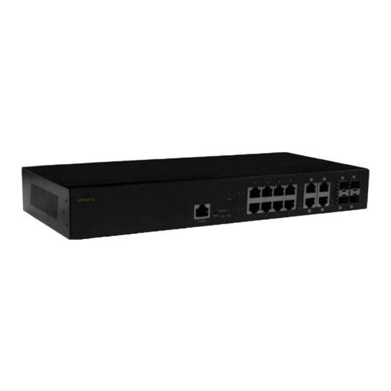
- Page 1 EPS-3112 Management Layer 2 Gigabit PoE Ethernet Switch 8 PoE ports 10/100/1000Mbps RJ-45 + 4 combo uplink ports (10/100/1000 Mbps RJ-45 and 100/1000Mbps SFP slot) User’s Guide Version 0.90...
- Page 2 Trademarks CTS is a registered trademark of Connection Technology Systems Inc All trademarks belong to their respective proprietor Contents are subject to change without prior notice.
- Page 3 Revision History Version Date Description 0.90 20170822 First release...
-
Page 4: Table Of Contents
Table of Contents 1. INTRODUCTION ................... 5 1.1 The Managed Switch ................5 1.2 Key Features .................... 5 1.3 Front & Rear Panel ................... 8 1.4 Cable Specifications ................. 9 1.5 Network Management ................10 2. INSTALLATION ................... 12 2.1 Requirement ................... 12 2.2 Checking the Package Contents ............ -
Page 5: Introduction
1. INTRODUCTION The Managed Switch is designed to meet the emerging FTTX & Metro Ethernet requirement. Its low profile appearance with 1U height and standard rack- mount size achieves the highest density within a single rack. When massive fiber ports need to be deployed, the Managed Switch provides the best performance and price ratio. - Page 6 IEEE 802.1ab LLDP IEEE 802.1p Priority IEEE 802.1q Tag VLAN IEEE 802.1d STP IEEE 802.1w RSTP IEEE 802.1x Port based Network Access Control IEEE 802.3af Power over Ethernet IEEE 802.3at Power over Ethernet Enhancements Features H/W Specification MAC Address Table: 8K Non-Blocking Switching Fabric: 24Gbps Memory Buffer: 524.5K Bytes VLAN Groups: 2K VLAN Groups...
- Page 7 Multicast IGMP Snooping v1/v2/v3 IGMP Fast Leave MLD v1/v2 Snooping IP Multicast Filter with Segment & Profile Static Multicast Configuration IPv6 Feature IPv6 over Ethernet (RFC 2464) IPv6 Addressing Architecture (RFC 4291) IPv6 Dual Stack (RFC4213) ICMPv6 (RFC4884) Path MTU Discovery for IPv6 (RFC 1981) Neighbor Discovery (RFC4861) Access Control List ACL Based on Physical port, EtherType ,VID , TOS/DSCP , Protocol...
-
Page 8: Front & Rear Panel
DHCP Auto-provision via DHCP option 60/43 for firmware and configuration upgrade Other Loop Detection Monitoring CPU and Memory Statistics Switch Port Status , Traffic , packet Error , Packet Analysis Statics Power Requirement Input AC:100V-240V 50/60Hz Environmental Condition Operation : 0℃ ~ 50℃ Storage Temperature : -20℃... -
Page 9: Cable Specifications
Please refer to chapter 3.1 LED Definitions Reset Button: Pressing reset button for 5~10 seconds then release to restart the system. Pressing reset button for more than 10 seconds then release to reset the Managed Switch back to factory settings and restart the system. -
Page 10: Network Management
(30km/50km) SFP Transceiver for 1000BASE-ZX Single-mode fiber module (80km) 1.5 Network Management This Managed Switch is Plug & Play compliant. Real-time operational status can be monitored through a set of LED indicators located in the front panel. Built-in management module also allows users to configure, control and monitor the system remotely. - Page 11 Please refer to the Network Management User’s Manual for the detailed management functions and required installation and operation procedures.
-
Page 12: Installation
2. INSTALLATION To properly install the Managed Switch, please follow the procedures listed below. These procedures are described below in separate sections. Installation Requirements Unpacking the Managed Switch Installing the Managed Switch Power on the Managed Switch ... -
Page 13: Install The Managed Switch
If any item is found missing or damaged, please contact your local sales representative for support or replacement. 2.3 Install the Managed Switch CAUTION To prevent any damage or failure of the Managed Switch, please DO NOT block the ventilation vents. Use the following guidelines when choosing a place to install the Switch: ... -
Page 14: Power On
WARNING! Please mount the Switch firmly in rack otherwise it may be fall and cause the system damage and possible injury to personnel. The Managed Switch can be mounted in an EIA standard-sized, 19-inch rack, which can be placed in a wiring closet with other equipment. Rack mounting brackets are provided to mount the Switch. -
Page 15: Connect The Switch To Network
In the event of power failure, unplug the power that is plugged into the switch at the back of the device. When power is resumed, plug the power back to the switch. 2.5 Connect the Switch to network Connect to Network The Managed Switch has 8 PoE 10/100/1000BASE-T RJ-45 ports and 4 combo ports in front panel. -
Page 16: Operation
3. OPERATION The Managed Switch is Plug & Play compliant. Real-time operational status can be monitored through a set of LED indicators located in the front panel. A built-in management module provides users flexible interfaces to configure, control and monitor the complete system remotely. 3.1 LED Definitions SYS LED The “SYS”... - Page 17 F/O Port LED 9~12 Color Operation Definition Port link is down Green Link is up and works at 100Mbps. Green Blinking Receiving and transmitting data. SFP Port 9~12 Port Status Orange Link is up and works at 1000Mbps. Orange Receiving and transmitting data. Blinking PoE LED Color...
-
Page 18: Maintenance
4. MAINTENANCE This Managed Switch is easy to maintain. The procedures are suggested when you want to identify faults, perform hardware replacement and Firmware upgrade. 4.1 Fault Identification Identifying faults can greatly reduce the times required to find problem and solution. -
Page 19: Firmware Upgrade
Failure to observe this warning could result in personal injury or death from electrical shock. Failure to observe the above warning will immediately void any Warranty. 4.3 Firmware Upgrade This Managed Switch may perform Firmware upgrade when required. New Firmware can be obtained from your sales representative. Please check the Network anagement User’s Manual for the detailed upgrade procedures.
Need help?
Do you have a question about the EPS-3112 and is the answer not in the manual?
Questions and answers