Table of Contents
Advertisement
Quick Links
Advertisement
Table of Contents

Related Manuals for CTS EPS-3128 Series


Summary of Contents for CTS EPS-3128 Series
- Page 1 EPS-3128 Series 28-port L2+ Managed Ethernet PoE Switch User’s Guide Version: 1.0...
-
Page 2: Revision History
This is a Class A product. In a domestic environment, this product may cause radio interference in which case the user may be required to take adequate measures. Trademarks CTS is a registered trademark of Connection Technology Systems Inc All trademarks belong to their respective proprietor Contents subject to change without prior notice. -
Page 3: Cts Contact Information
CTS Contact Information Headquarter/Manufacturer: ▓ Connection Technology Systems Inc. 18F-6, No.79, Sec.1, Xintai 5th Rd., XiZhi Dist., New Taipei City 221, Taiwan(R.O.C) Tel: +886-2-2698-9661 Fax: +886-2-2698-9662 Dir.Line:+886-2-2698-9201 www.ctsystem.com Global Authorized Representatives: ▓ Connection Technology USA Inc. Connection Technology Systems Japan... -
Page 4: Table Of Contents
Table of Contents Revision History ..................ii CTS CONTACT INFORMATION ..............III TABLE OF CONTENTS ................IV CHAPTER 1. INTRODUCTION ..............2 1.1 O EPS-3128 ..............2 VERVIEW OF 1.2 K .................. 3 EATURES 1.3 F & R ................. 5... - Page 5 About this manual In this user’s guide, it will not only clearly introduce CTS EPS-3128 Managed Switch but tell you how to install this Managed Switch with detailed instructions. Organization of the Manual Chapter 1 “Introduction” describes the features of the Managed Switch ...
-
Page 6: Chapter 1. Introduction
Introduction Introduction CTS’s Managed Switch is designed to meet the emerging FTTX & Metro Ethernet requirements. Its low profile appearance with 1U height and the standard rack-mounted size achieve the highest density within a single rack. When massive fiber ports need to be deployed, the Managed Switch provides the best performance and price ratio. -
Page 7: Key Features
Introduction 1.2 Key Features 19 inch, 1U high 24 x 10/100/1000Base-T ports, Max.30W PoE/PSE IEEE 802.3/802.3u/802.3ab compliance Support Auto-Negotiation Support MDI/MDIX/Auto-Crossover RJ-45 Slot Support IEEE802.3af Power over Ethernet Support IEEE802.3at Power over Ethernet Enhancements 4 x 10/100/1000Base-T, 100/1000Base-X Combo ports IEEE 802.3ab/802.3z compliance Support Auto-Negotiation (RJ-45) and Auto-Sensing (SFP) Support MDI/MDIX/Auto-Crossover(RJ-45) - Page 8 Introduction Maximum PoE Power Budget : For 480W model: 480Watts at 40°C, 420Watts at 50°C For 240W model: 240Watts at 40°C, 210Watts at 50°C Time Range for PoE L2PT (Layer 2 Protocol Tunneling) VLAN Translation Proprietary Fast Ring v2 (<50ms) and Chain (<1 second) redundancy protocols for fast redundancy after encountering connection issues ...
-
Page 9: Front & Rear Panels
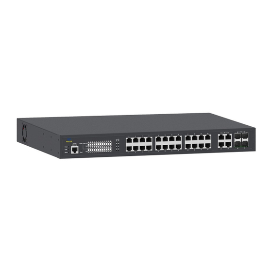
Introduction 1.3 Front & Rear Panels 1.3.1 Front Panel Figure 1-1. Front Panel of EPS-3128 Managed Switch The interfaces on the front panel of the Managed Switch are described below: 24 x 10/100/1000Base-T RJ-45 ports (Ports 1-24) 4 x Gigabit combo ports (Ports 25-28): ... -
Page 10: Rear Panel
Introduction 1.3.2 Rear Panel The Managed Switch provides one fixed AC input power module. Figure 1-2. Rear Panel of EPS-3128 Managed Switch The interface on the rear panel of the Managed Switch is described below: AC Inlet AC power connection: 100-240V, 50/60Hz Power Switch: ... -
Page 11: Led Definitions
Introduction 1.4 LED Definitions The Managed Switch is Plug & Play compliant. The real-time operational status can be monitored through a set of LED indicators located in the front panel. Figure 1-3. LEDs of EPS-3128 Managed Switch Power LED The power status of the Managed Switch is indicated by the Power LED on the front panel of the device. - Page 12 Introduction Slowly blinking when you press the Reset button for 13~20 seconds. And then release the Reset button, the LED indicator will continuously blink in orange green color by turns until the system is reset to default (return to supplier default settings) and restart the system.
- Page 13 Introduction TP & F/O 25~28 Port LEDs Media Color Operation Type No connection exists. Lit when the 10/100Mbps port link is up. Green Blinking when TP port is receiving and transmitting data at the speed of 10/100Mbps. Lit when the 1000Mbps port link is up. Orange Blinking when TP port is receiving and transmitting data at the speed of 1000Mbps.
-
Page 14: Cable Specifications
Introduction 1.5 Cable Specifications The following table contains various cable specifications for the Managed Switch. Please make sure that you use the proper cable when connecting the Managed Switch. Cable Type Description UTP Category 3, 4, 5 (100 meters max.) 10Base-T EIA/TIA- 568 150-ohm STP (100 meters max.) UTP Cat. -
Page 15: Installation
Installation Installation To properly install the EPS-3128 Managed Switch, please follow the procedures listed below. These procedures will be respectively described in detail in the following sections. Installation Requirements Checking the Package Contents Installing the Managed Switch ... -
Page 16: Installation Requirements
Installation 2.1 Installation Requirements Basic requirements for installation are as follows: Environmental conditions One power outlet Proper ventilation Proper isolation to electrical noise, radio, etc. UTP cables should not run in the same duct with power and phone line cables ... -
Page 17: Installing The Managed Switch
Installation 2.3 Installing the Managed Switch You can install the EPS-3128 switch on a flat surface or mount it in a standard 19-inch network equipment rack. CAUTION To prevent any damage or failure of the Managed Switch, please DO NOT block the ventilation FAN holes. -
Page 18: Rack Installation
Installation 2.3.2 Rack Installation In the following section, we will take the EPS-3128 Managed Switch for example to install a 19-inch switch in a standard 19-inch network equipment rack. WARNING! Please mount the Switch firmly in rack, otherwise it may fall and cause the system damage and possible injury to personnel. -
Page 19: Grounding The Managed Poe Gigabit Ethernet Switch
Installation 2.3.3 Grounding the Managed PoE Gigabit Ethernet Switch Grounding helps to limit the effects of noise due to electromagnetic interference (EMI). Be sure to install the ground connection from the ground screw to the grounding surface before connecting devices. Figure 2-2 Grounding Wiring for EPS-3128 Publication date: Nov. -
Page 20: Powering On The Managed Switch
Installation 2.4 Powering on the Managed Switch The Managed Switch can be used with AC power supply 100-240V, 50–60Hz. After the Managed Switch is turned on, the Power LED indicators should light in green color and the FAN should spin. For more details about the power LED description, please refer to Section 1.4 LED Definitions. -
Page 21: Removing Sfp Modules
Installation 2.6.2 Removing SFP Modules To disconnect an LC connector, use the following guidelines: 1. Press down and hold the locking clips on the upper side of the optic cable. 2. Pull the optic cable out to release it from the transceiver. 3. -
Page 22: Operation
Operation Operation A built-in management module of Managed Switch provides users flexible interfaces to configure, control and monitor the system remotely and locally. To know the further information about the operation of Managed Switch, please refer to EPS-3128 Network Management User’s Manual for the detailed management functions and required installation and operation procedures. - Page 23 Operation SNMP Management SNMP is also In-Band-Management and requires a network connection to the Managed Switch. The Managed Switch private Management Information Bases (MIB) is provided for SNMP-based network management program to configure, control and monitor the system. Web Management Web Management is done over the network.
-
Page 24: Chapter 4. Maintenance
Maintenance Maintenance This Managed Switch is easy to maintain. The procedures are suggested when you would like to identify faults, perform hardware replacement and firmware upgrade. 4.1 Fault Identification Identifying faults can greatly reduce the times required to find problem and solution. Users may perform local check or remote check to find the problems. -
Page 25: Remote Check
Maintenance 4.1.2 Remote Check Users may check the Managed Switch through SNMP manager remotely. For detailed procedures, please refer to the Network Management User’s Manual. 4.2 Hardware Replacement Procedures WARNING! The Managed Switch contains no user-serviceable parts. DO NOT, UNDER ANY CIRCUMSTANCES, open and attempt to repair it. - Page 27 18F-6, No.79, Sec.1, Xintai 5th Rd., XiZhi Dist., New Taipei City 221, Taiwan(R.O.C) Tel: +886-2-2698-9661 Fax: +886-2-2698-9662 Dir.Line:+886-2-2698-9201 www.ctsystem.com...
Need help?
Do you have a question about the EPS-3128 Series and is the answer not in the manual?
Questions and answers